fuel filter INFINITI QX56 2008 Factory Service Manual
[x] Cancel search | Manufacturer: INFINITI, Model Year: 2008, Model line: QX56, Model: INFINITI QX56 2008Pages: 4083, PDF Size: 81.73 MB
Page 8 of 4083

2008
QUICK REFERENCE CHART: QX56
Front Disc Brake
INFOID:0000000006237753
Unit: mm (in)
Rear Disc BrakeINFOID:0000000006237754
Unit: mm (in)
Fluids and LubricantsINFOID:0000000006237752
Brake model AD41VA
Brake pad Standard thickness (new) 12.0 (0.476)
Repair limit thickness 1.0 (0.039)
Disc rotor Standard thickness (new) 30 (1.181)
Repair limit thickness 28 (1.102)
Maximum uneven wear (measured at 8 positions) 0.015 (0.0006)
Runout limit (with it attached to the vehicle) 0.03 (0.001)
Brake model
AD14VE
Brake pad Standard thickness (new) 12.0 (0.472)
Repair limit thickness 1.0 (0.039)
Disc rotor Standard thickness (new) 14.0 (0.551)
Repair limit thickness 12.5 (0.492)
Maximum uneven wear (measured at 8 positions) 0.015 (0.0006)
Runout limit (with it attached to the vehicle) 0.05 (0.002)
Description
Capacity (Approximate)
Metric US measure Imp measure
Fuel 105.8 28 gal 23 1/4 gal
Engine oil
Drain and refill With oil filter change
6.5 6 7/8 qt 5 3/4 qt
Without oil filter change 6.2 6 1/2 qt 5 1/2 qt
Dry engine (engine overhaul) 7.6 8 qt 6 3/4 qt
Cooling system With reservoir
at MAX level
14.4
15 1/4 qt 12 5/8 qt
Automatic transmission fluid (ATF) 10.6 11 1/4 qt 9 3/8 qt
Rear final drive oil 1.75 3 3/4 pt 3 1/8 pt
Transfer fluid 3.0 3 1/8 qt 2 5/8 qt
Front final drive oil 1.6 3 3/8 pt 2 7/8 pt
Power steering fluid (PSF) 1.0 1 1/8 qt 7/8 qt
Brake fluid — — —
Brake grease — — —
Multi-purpose grease — — —
Windshield washer fluid 4.9 5 1/8 qt 4 3/8 qt
Air conditioning system refrigerant 1.08 ± 0.05 kg 2.38 ± 0.11 lb 2.38 ± 0.11 lb
Air conditioning system oil 290 m9.8 fl oz 10.2 fl oz
Page 1377 of 4083
![INFINITI QX56 2008 Factory Service Manual EC-78
< COMPONENT DIAGNOSIS >[VK56DE]
TROUBLE DIAGNOSIS - SPECIFICATION VALUE
Check “A/F ALPHA-B1”, “A/F ALPHA-B2” for approximat
ely 1 minute because they may fluctuate. It is NG
if the indic INFINITI QX56 2008 Factory Service Manual EC-78
< COMPONENT DIAGNOSIS >[VK56DE]
TROUBLE DIAGNOSIS - SPECIFICATION VALUE
Check “A/F ALPHA-B1”, “A/F ALPHA-B2” for approximat
ely 1 minute because they may fluctuate. It is NG
if the indic](/img/42/57030/w960_57030-1376.png)
EC-78
< COMPONENT DIAGNOSIS >[VK56DE]
TROUBLE DIAGNOSIS - SPECIFICATION VALUE
Check “A/F ALPHA-B1”, “A/F ALPHA-B2” for approximat
ely 1 minute because they may fluctuate. It is NG
if the indication is out of the SP value even a little.
OK or NG
OK >> GO TO 17.
NG (Less than the SP value)>>GO TO 2.
NG (More than the SP value)>>GO TO 3.
2.CHECK “B/FUEL SCHDL”
Select “B/FUEL SCHDL” in “SPEC” of “DATA MONITOR” mode, and make sure that the indication is within the
SP value.
OK or NG
OK >> GO TO 4.
NG (More than the SP value)>>GO TO 19.
3.CHECK “B/FUEL SCHDL”
Select “B/FUEL SCHDL” in “SPEC” of “DATA MONITOR” mode, and make sure that the indication is within the
SP value.
OK or NG
OK >> GO TO 6.
NG (More than the SP value)>>GO TO 6.
NG (Less than the SP value)>>GO TO 25.
4.CHECK “A/F ALPHA-B1”, “A/F ALPHA-B2”
1. Stop the engine.
2. Disconnect PCV hose, and then plug it.
3. Start engine.
4. Select “A/F ALPHA-B1”, “A/F AL PHA-B2” in “SPEC” of “DATA MONITOR” mode, and make sure that the
each indication is within the SP value.
OK or NG
OK >> GO TO 5.
NG >> GO TO 6.
5.CHANGE ENGINE OIL
1. Stop the engine.
2. Change engine oil. NOTE:
This symptom may occur when a large amount of gasoline is mixed with engine oil because of driving
conditions (such as when engine oil temperature does not rise enough since a journey distance is too
short during winter). The symptom will not be detected after changing engine oil or changing driving con-
dition.
>>INSPECTION END
6.CHECK FUEL PRESSURE
Check fuel pressure. (Refer to EC-494, "
Fuel Pressure Check" .)
OK or NG
OK >> GO TO 9.
NG (Fuel pressure is too high)>>Replace fuel pressure regulator, refer to EC-494, "
Fuel Pressure Check" .
GO TO 8.
NG (Fuel pressure is too low)>>GO TO 7.
7.DETECT MALFUNCTIONING PART
1. Check the following.
- Clogged and bent fuel hose and fuel tube
- Clogged fuel filter
- Fuel pump and its circuit (Refer to EC-494, "
Fuel Pressure Check" .)
2. If NG, repair or replace the malfunctioning part. (Refer to EC-494, "
Fuel Pressure Check" .)
If OK, replace fuel pressure regulator.
Revision: March 2010 2008 QX56
Page 1479 of 4083
![INFINITI QX56 2008 Factory Service Manual EC-180
< COMPONENT DIAGNOSIS >[VK56DE]
P0171, P0174 FUEL INJECTION SYSTEM FUNCTION
5. Check harness continuity between the following terminals and ground.
Refer to Wiring Diagram.
6. Also check harnes INFINITI QX56 2008 Factory Service Manual EC-180
< COMPONENT DIAGNOSIS >[VK56DE]
P0171, P0174 FUEL INJECTION SYSTEM FUNCTION
5. Check harness continuity between the following terminals and ground.
Refer to Wiring Diagram.
6. Also check harnes](/img/42/57030/w960_57030-1478.png)
EC-180
< COMPONENT DIAGNOSIS >[VK56DE]
P0171, P0174 FUEL INJECTION SYSTEM FUNCTION
5. Check harness continuity between the following terminals and ground.
Refer to Wiring Diagram.
6. Also check harness for short to power.
OK or NG
OK >> GO TO 4.
NG >> Repair open circuit or short to ground or short to power in harness or connectors.
4.CHECK FUEL PRESSURE
1. Release fuel pressure to zero. Refer to EC-494, "
Fuel Pressure Check".
2. Install fuel pressure gauge and check fuel pressure. Refer to EC-494, "
Fuel Pressure Check".
OK or NG
OK >> GO TO 6.
NG >> GO TO 5.
5.DETECT MALFUNCTIONING PART
Check the following.
• Fuel pump and circuit (Refer to EC-402, "
Diagnosis Procedure".)
• Fuel pressure regulator (Refer to EC-494, "
Fuel Pressure Check".)
• Fuel lines
• Fuel filter for clogging
>> Repair or replace.
6.CHECK MASS AIR FLOW SENSOR
With CONSULT-III
1. Install all removed parts.
2. Check “MASS AIR FLOW” in “DATA MONITOR” mode with CONSULT-III.
With GST
1. Install all removed parts.
2. Check mass air flow sensor signal in Service $01 with GST.
A/F sensor 1 terminal ECM terminal
Bank 1 13
5
25 6
Bank 2 11
6
27 5
Continuity should exist.
Bank 1 Bank 2
A/F sensor 1 terminal ECM terminal A/F sensor 1 terminal ECM terminal 13 511 6
25 627 5
Continuity should not exist.
At idling: Approximately 350 kPa (3.57 kg/cm2, 51 psi)
3.0 - 9.0 g·m/sec: at idling
9.0 - 28.0 g·m/sec: at 2,500 rpm
Revision: March 2010 2008 QX56
Page 1501 of 4083
![INFINITI QX56 2008 Factory Service Manual EC-202
< COMPONENT DIAGNOSIS >[VK56DE]
P0300, P0301, P0302, P
0303, P0304, P0305, P0306, P0307, P0308 MISFIRE
OK or NG
OK >> GO TO 12.
NG >> GO TO 11.
11 .DETECT MALFUNCTIONING PART
Check the followi INFINITI QX56 2008 Factory Service Manual EC-202
< COMPONENT DIAGNOSIS >[VK56DE]
P0300, P0301, P0302, P
0303, P0304, P0305, P0306, P0307, P0308 MISFIRE
OK or NG
OK >> GO TO 12.
NG >> GO TO 11.
11 .DETECT MALFUNCTIONING PART
Check the followi](/img/42/57030/w960_57030-1500.png)
EC-202
< COMPONENT DIAGNOSIS >[VK56DE]
P0300, P0301, P0302, P
0303, P0304, P0305, P0306, P0307, P0308 MISFIRE
OK or NG
OK >> GO TO 12.
NG >> GO TO 11.
11 .DETECT MALFUNCTIONING PART
Check the following.
• Fuel pump and circuit (Refer to EC-402, "
Diagnosis Procedure".)
• Fuel pressure regulator (Refer to EC-494, "
Fuel Pressure Check".)
• Fuel lines
• Fuel filter for clogging
>> Repair or replace.
12.CHECK IGNITION TIMING
Check the following items. Refer to EC-13, "
Basic Inspection".
OK or NG
OK >> GO TO 13.
NG >> Follow the EC-13, "
Basic Inspection".
13.CHECK A/F SENSOR 1 INPUT SIGNAL
1. Turn ignition switch OFF.
2. Disconnect A/F sensor 1 harness connector.
3. Disconnect ECM harness connector.
4. Check harness continuity between the following terminals. Refer to Wiring Diagram.
5. Check harness continuity between the following terminals and ground. Refer to Wiring Diagram.
Items Specifications
Target idle speed 650 ± 50 rpm (in P or N position)
Ignition timing 15 ± 5 ° BTDC (in P or N position)
A/F sensor 1 terminal ECM terminal
Bank 1 13
5
25 6
Bank 2 11
6
27 5
Continuity should exist.
Bank 1 Bank 2
A/F sensor 1 terminal ECM terminal A/F sensor 1 terminal ECM terminal 13 511 6
25 627 5
BBIA0376E
Revision: March 2010 2008 QX56
Page 1783 of 4083
![INFINITI QX56 2008 Factory Service Manual EC-484
< SYMPTOM DIAGNOSIS >[VK56DE]
ENGINE CONTROL SYSTEM SYMPTOMS
1 - 6: The numbers refer to the order of inspection.Exhaust Exhaust manifold/Tube/Muffler/
Gasket 55555 55 5EM-30
,
EX-
5Three way INFINITI QX56 2008 Factory Service Manual EC-484
< SYMPTOM DIAGNOSIS >[VK56DE]
ENGINE CONTROL SYSTEM SYMPTOMS
1 - 6: The numbers refer to the order of inspection.Exhaust Exhaust manifold/Tube/Muffler/
Gasket 55555 55 5EM-30
,
EX-
5Three way](/img/42/57030/w960_57030-1782.png)
EC-484
< SYMPTOM DIAGNOSIS >[VK56DE]
ENGINE CONTROL SYSTEM SYMPTOMS
1 - 6: The numbers refer to the order of inspection.Exhaust Exhaust manifold/Tube/Muffler/
Gasket 55555 55 5EM-30
,
EX-
5Three way catalyst
Lubrica-
tion Oil pan/Oil strainer/Oil pump/Oil
filter/Oil gallery/Oil cooler
55555 55 5EM-33
,
LU-
14 , LU-11 ,
LU-12
Oil level (Low)/Filthy oil LU-8, "In-
spection"
Cooling Radiator/Hose/Radiator filler cap
55555 55 45 CO-15
Thermostat
5CO-22
Water pump CO-20
Water galleryCO-6
Cooling fan5CO-18,
CO-
19
Coolant level (Low)/Contaminat-
ed coolant 5
CO-10
IVIS (INFINITI Vehicle Immobilizer System —
NATS) 11
SEC-8
SYMPTOM
Reference
page
HARD/NO START/RESTART (EXCP. HA)
ENGINE STALL
HESITATION/SURGING/FLAT SPOT
SPARK KNOCK/DETONATION
LACK OF POWER/POOR ACCELERATION
HIGH IDLE/LOW IDLE
ROUGH IDLE/HUNTING
IDLING VIBRATION
SLOW/NO RETURN TO IDLE
OVERHEATS/WATER TEMPERATURE HIGH
EXCESSIVE FUEL CONSUMPTION
EXCESSIVE OIL CONSUMPTION
BATTERY DEAD (UNDER CHARGE)
Warranty symptom code AA AB AC AD AE AF AG AH AJ AK AL AM HA
Revision: March 2010 2008 QX56
Page 1794 of 4083
![INFINITI QX56 2008 Factory Service Manual FUEL PRESSUREEC-495
< ON-VEHICLE MAINTENANCE > [VK56DE]
C
D
E
F
G H
I
J
K L
M A
EC
NP
O
8. If result is unsatisfactory, go to next step.
9. Check the following.
• Fuel hoses and fuel tubes for clogg INFINITI QX56 2008 Factory Service Manual FUEL PRESSUREEC-495
< ON-VEHICLE MAINTENANCE > [VK56DE]
C
D
E
F
G H
I
J
K L
M A
EC
NP
O
8. If result is unsatisfactory, go to next step.
9. Check the following.
• Fuel hoses and fuel tubes for clogg](/img/42/57030/w960_57030-1793.png)
FUEL PRESSUREEC-495
< ON-VEHICLE MAINTENANCE > [VK56DE]
C
D
E
F
G H
I
J
K L
M A
EC
NP
O
8. If result is unsatisfactory, go to next step.
9. Check the following.
• Fuel hoses and fuel tubes for clogging
• Fuel filter for clogging
• Fuel pump
• Fuel pressure regulator for clogging
If OK, replace fuel pressure regulator.
If NG, repair or replace.
10. Before disconnecting Fuel Pressure Gauge and Fuel Pressure Adapter J-44321-6, release fuel pressure
to zero. Refer to "FUEL PRESSURE RELEASE". At idling:
Approximately 350 kPa (3.57 kg/cm
2, 51 psi)
Revision: March 2010 2008 QX56
Page 1804 of 4083

EM-1
ENGINE
C
DE
F
G H
I
J
K L
M
SECTION EM
A
EM
N
O P
CONTENTS
ENGINE MECHANICAL
PRECAUTION ....... ........................................3
PRECAUTIONS .............................................. .....3
Precaution for Supplemental Restraint System
(SRS) "AIR BAG" and "SEAT BELT PRE-TEN-
SIONER" ............................................................. ......
3
Precaution Necessary for Steering Wheel Rota-
tion After Battery Disconnect ............................... ......
3
Precaution for Drain Engine Coolant .........................4
Precaution for Disconnecting Fuel Piping .................4
Precaution for Removal and Disassembly ................4
Precaution for Inspection, Repair and Replace-
ment .................................................................... ......
4
Precaution for Assembly and Installation ..................4
Parts Requiring Angular Tightening ..........................4
Precaution for Liquid Gasket ............................... ......5
PREPARATION ............................................6
PREPARATION .............................................. .....6
Special Service Tool ........................................... ......6
Commercial Service Tool ..........................................8
FUNCTION DIAGNOSIS ..............................10
NOISE, VIBRATION, AND HARSHNESS
(NVH) TROUBLESHOOTING ........................ ....
10
NVH Troubleshooting - Engine Noise ................. ....10
Use the Chart Below to Help You Find the Cause
of the Symptom .......................................................
11
ON-VEHICLE MAINTENANCE ....................13
DRIVE BELTS ................................................ ....13
Checking Drive Belts ........................................... ....13
Removal and Installation .........................................13
Drive Belt Auto Tensioner and Idler Pulley ......... ....14
AIR CLEANER FILTER ......................................15
Removal and Installation (Viscous paper type) ... ....15
SPARK PLUG ................................................ ....16
Removal and Installation ..................................... ....16
CAMSHAFT VALVE CLEARANCE ..................18
Valve Clearance ......................................................18
COMPRESSION PRESSURE ...........................23
Checking Compression Pressure ............................23
ON-VEHICLE REPAIR .................................24
ENGINE ROOM COVER ...................................24
Removal and Installation ..................................... ....24
AIR CLEANER AND AIR DUCT .......................25
Removal and Installation .........................................25
INTAKE MANIFOLD .........................................26
Removal and Installation .........................................26
EXHAUST MANIFOLD AND THREE WAY
CATALYST ........................................................
30
Exploded View .........................................................30
Removal and Installation .........................................30
OIL PAN AND OIL STRAINER .........................33
Removal and Installation .........................................33
IGNITION COIL .................................................37
Removal and Installation .........................................37
ROCKER COVER .............................................38
Removal and Installation .........................................38
FUEL INJECTOR AND FUEL TUBE ................40
Removal and Installation .........................................40
TIMING CHAIN ..................................................44
Components ........................................................ ....44
Removal and Installation .........................................45
CAMSHAFT .......................................................53
Components ............................................................53
Removal and Installation .........................................53
Revision: March 2010 2008 QX56
Page 2101 of 4083

FL-1
ENGINE
C
DE
F
G H
I
J
K L
M
SECTION FL
A
FL
N
O P
CONTENTS
FUEL SYSTEM
PRECAUTION ....... ........................................2
PRECAUTIONS .............................................. .....2
Precaution for Supplemental Restraint System
(SRS) "AIR BAG" and "SEAT BELT PRE-TEN-
SIONER" ............................................................. ......
2
Precaution Necessary for Steering Wheel Rota-
tion After Battery Disconnect ............................... ......
2
FUEL SYSTEM ....................................................4
General Precaution ............................................. ......4
PREPARATION ............................................5
PREPARATION .............................................. .....5
Special Service Tool ........................................... ......5
Commercial Service Tool ..........................................5
BASIC INSPECTION ....................................6
FUEL SYSTEM ............................................... .....6
Checking Fuel Line ............................................. ......6
REMOVAL AND INSTALLATION ................7
FUEL LEVEL SENSOR UNIT, FUEL FILTER
AND FUEL PUMP ASSEMBLY .........................
7
Removal and Installation ..................................... .....7
FUEL TANK ......................................................11
Removal and Installation ..................................... ....11
DISASSEMBLY AND ASSEMBLY ..............16
FUEL LEVEL SENSOR UNIT, FUEL FILTER
AND FUEL PUMP ASSEMBLY ........................
16
Disassembly and Assembly ................................. ....16
SERVICE DATA AND SPECIFICATIONS
(SDS) ............... .......................................... ...
17
SERVICE DATA AND SPECIFICATIONS
(SDS) .................................................................
17
Standard and Limit .............................................. ....17
Revision: March 2010 2008 QX56
Page 2107 of 4083

FUEL LEVEL SENSOR UNIT, FUEL FILTER AND FUEL PUMP ASSEMBLYFL-7
< REMOVAL AND INSTALLATION >
C
DE
F
G H
I
J
K L
M A
FL
NP
O
REMOVAL AND INSTALLATION
FUEL LEVEL SENSOR UNIT, FUEL FI
LTER AND FUEL PUMP ASSEMBLY
Removal and InstallationINFOID:0000000004900805
REMOVAL
WARNING:
Follow the “General Precautions” before working on the fuel system. Refer to FL-4, "
General Precau-
tion" .
1. Remove the fuel filler cap to release the pressure from inside the fuel tank.
2. Check the fuel level on level gauge. If the fuel gauge indicates more than the level as shown (full or almost full), drain the fuel
from the fuel tank until the fuel gauge indicates the level as
shown, or less.
• If the fuel pump does not operate, use the following procedureto drain the fuel to the specified level.
a. Insert a suitable hose of less than 15 mm (0.59 in) diameter into the fuel filler pipe through the fuel filler opening to drain the fuel
from fuel filler pipe.
b. Remove the LH rear wheel and tire. Refer to WT-48, "
Rotation" .
c. Remove the four clips and remove the rear fender protector, front.
1. Inspection hole cover 2. Inspection hole cover O-ring 3. Lock ring
4. Fuel level sensor, fuel filter, and fuel pump assembly 5. Fuel tank
6. Fuel level sensor, fuel filter, and fuel
pump assembly O-ring
LBIA0381E
WBIA0390E
Revision: March 2010 2008 QX56
Page 2108 of 4083

FL-8
< REMOVAL AND INSTALLATION >
FUEL LEVEL SENSOR UNIT, FUEL FILTER AND FUEL PUMP ASSEMBLY
d. Disconnect the fuel filler hose from the fuel filler pipe.
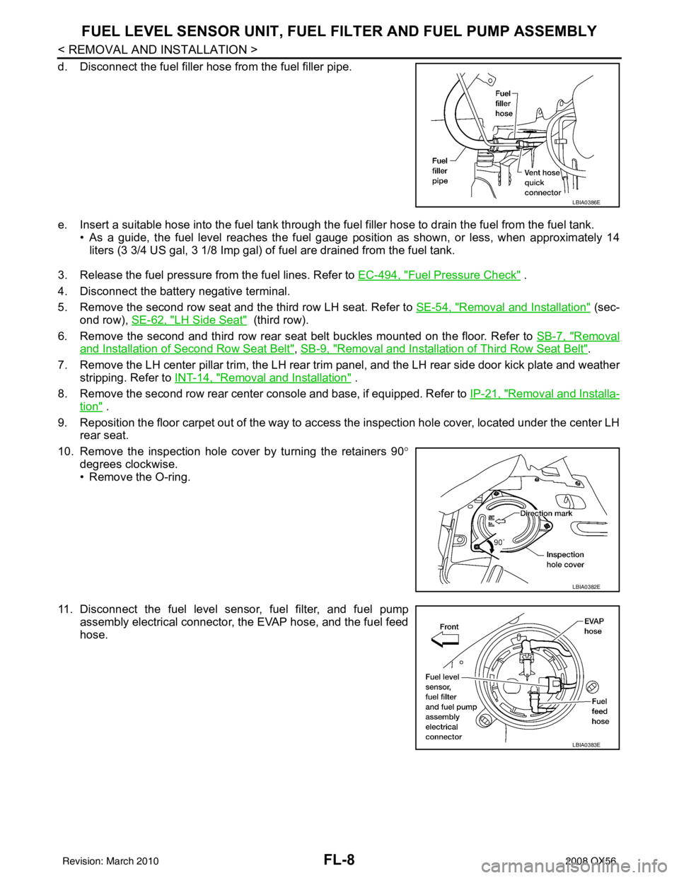
e. Insert a suitable hose into the fuel tank through the fuel filler hose to drain the fuel from the fuel tank.
• As a guide, the fuel level reaches the fuel gauge position as shown, or less, when approximately 14
liters (3 3/4 US gal, 3 1/8 Imp gal) of fuel are drained from the fuel tank.
3. Release the fuel pressure from the fuel lines. Refer to EC-494, "
Fuel Pressure Check" .
4. Disconnect the battery negative terminal.
5. Remove the second row seat and the third row LH seat. Refer to SE-54, "
Removal and Installation" (sec-
ond row), SE-62, "
LH Side Seat" (third row).
6. Remove the second and third row rear seat belt buckles mounted on the floor. Refer to SB-7, "
Removal
and Installation of Second Row Seat Belt", SB-9, "Removal and Installation of Third Row Seat Belt".
7. Remove the LH center pillar trim, the LH rear trim panel, and the LH rear side door kick plate and weather
stripping. Refer to INT-14, "
Removal and Installation" .
8. Remove the second row rear center console and base, if equipped. Refer to IP-21, "
Removal and Installa-
tion" .
9. Reposition the floor carpet out of the way to access the inspection hole cover, located under the center LH
rear seat.
10. Remove the inspection hole cover by turning the retainers 90 °
degrees clockwise.
• Remove the O-ring.
11. Disconnect the fuel level sensor, fuel filter, and fuel pump assembly electrical connector, the EVAP hose, and the fuel feed
hose.
LBIA0386E
LBIA0382E
LBIA0383E
Revision: March 2010 2008 QX56