height INFINITI QX56 2008 Factory Service Manual
[x] Cancel search | Manufacturer: INFINITI, Model Year: 2008, Model line: QX56, Model: INFINITI QX56 2008Pages: 4083, PDF Size: 81.73 MB
Page 6 of 4083
2008
QUICK REFERENCE CHART: QX56
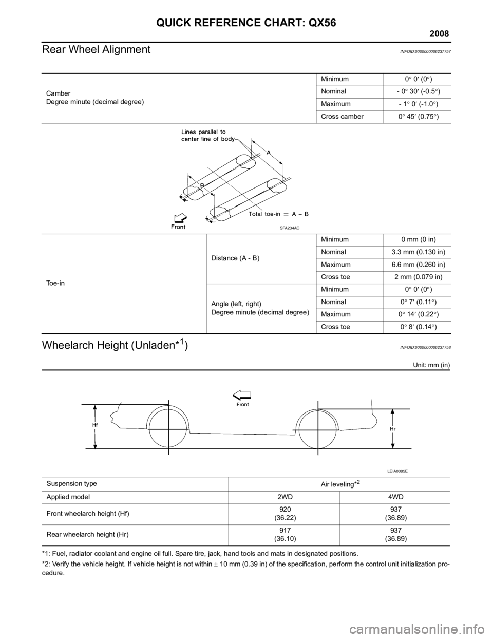
Rear Wheel Alignment
INFOID:0000000006237757
Wheelarch Height (Unladen*1)INFOID:0000000006237758
Unit: mm (in)
*1: Fuel, radiator coolant and engine oil full. Spare tire, jack, hand tools and mats in designated positions.
*2: Verify the vehicle height. If vehicle height is not within ± 10 mm (0.39 in) of the specification, perform the control unit initialization pro-
cedure. Camber
Degree minute (decimal degree)
Minimum 0
° 0 ′ (0 °)
Nominal - 0 ° 30 ′ (-0.5 °)
Maximum - 1 ° 0 ′ (-1.0 °)
Cross camber 0 ° 45 ′ (0.75 °)
To e - i n Distance (A - B)
Minimum 0 mm (0 in)
Nominal 3.3 mm (0.130 in)
Maximum 6.6 mm (0.260 in)
Cross toe 2 mm (0.079 in)
Angle (left, right)
Degree minute (decimal degree) Minimum 0
° 0 ′ (0 °)
Nominal 0 ° 7 ′ (0.11 °)
Maximum 0 ° 14 ′ (0.22 °)
Cross toe 0 ° 8 ′ (0.14 °)
SFA234AC
Suspension type
Air leveling*2
Applied model 2WD 4WD
Front wheelarch height (Hf)920
(36.22) 937
(36.89)
Rear wheelarch height (Hr) 917
(36.10) 937
(36.89)
LEIA0085E
Page 7 of 4083
QUICK REFERENCE CHART: QX56
2008
Brake SpecificationsINFOID:0000000006237755
Unit: mm (in)
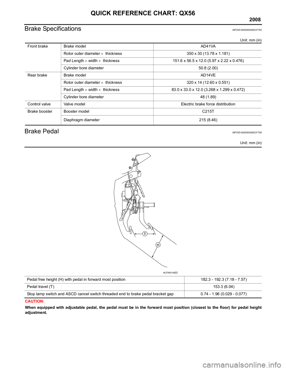
Brake PedalINFOID:0000000006237756
Unit: mm (in)
CAUTION:
When equipped with adjustable pedal, the pedal must be in the forward most position (closest to the floor) for pedal height
adjustment. Front brake Brake model AD41VA
Rotor outer diameter × thickness 350 x 30 (13.78 x 1.181)
Pad Length × width × thickness 151.6 x 56.5 x 12.0 (5.97 x 2.22 x 0.476)
Cylinder bore diameter 50.8 (2.00)
Rear brake Brake model AD14VE Rotor outer diameter × thickness 320 x 14 (12.60 x 0.551)
Pad Length × width × thickness 83.0 x 33.0 x 12.0 (3.268 x 1.299 x 0.472)
Cylinder bore diameter 48 (1.89)
Control valve Valve model Electric brake force distribution
Brake booster Booster model C215T
Diaphragm diameter 215 (8.46)
Pedal free height (H) with pedal in forward most position 182.3 - 192.3 (7.18 - 7.57)
Pedal travel (T) 153.3 (6.04)
Stop lamp switch and ASCD cancel switch threaded end to brake pedal bracket gap 0.74 - 1.96 (0.029 - 0.077)
ALFIA0149ZZ
Page 195 of 4083
![INFINITI QX56 2008 Factory Service Manual AV-14
< FUNCTION DIAGNOSIS >[AUDIO SYSTEM]
NAVIGATION SYSTEM
MAP–MATCHING
Map–matching is a function that repositions the vehicle on the road
map when a new location is judged to be the most accur INFINITI QX56 2008 Factory Service Manual AV-14
< FUNCTION DIAGNOSIS >[AUDIO SYSTEM]
NAVIGATION SYSTEM
MAP–MATCHING
Map–matching is a function that repositions the vehicle on the road
map when a new location is judged to be the most accur](/img/42/57030/w960_57030-194.png)
AV-14
< FUNCTION DIAGNOSIS >[AUDIO SYSTEM]
NAVIGATION SYSTEM
MAP–MATCHING
Map–matching is a function that repositions the vehicle on the road
map when a new location is judged to be the most accurate. This is
done by comparing the current vehicle position, calculated by the
method described in the position detection principle, with the road
map data around the vehicle, read from the map data stored on the
HDD.
Therefore, the vehicle position may not be corrected after the vehicle
is driven over a certain distance or time in which GPS information is
hard to receive. In this case, the current-location mark on the display
must be corrected manually.
CAUTION:
The road map data is based on data stored on the HDD.
• In map-matching, alternative rout
es to reach the destination will be
shown and prioritized, after the road on which the vehicle is cur-
rently driven has been judged and the current-location mark has
been repositioned.
If there is an error in distance and/or direction, the alternative
routes will be shown in different order of priority, and the wrong
road can be avoided.
If two roads are running in parallel, they are of the same priority.
Therefore, the current-location mark may appear on either of them
alternately, depending on maneuvering of the steering wheel and
configuration of the road.
• Map-matching does not function correctly when the road on which the vehicle is driving is new and not recorded on the HDD, or when
the road pattern stored in the m ap data and the actual road pattern
are different due to repair.
When driving on a road not present in the map, the map-matching
function may find another road and position the current-location
mark on it. Then, when the correct road is detected, the current-
location mark may leap to it.
• Effective range for comparing the vehicle position and travel direc-
tion calculated by the distance and direction with the road data
read from the HDD is limited. Therefore, when there is an exces-
sive gap between the current vehicle position and the position on
the map, correction by map-matching is not possible.
GPS (GLOBAL POSITIONING SYSTEM)
GPS (Global Positioning System) has been developed and con-
trolled by the US Department of Defense. The system utilizes GPS
satellite (NAVSTAR), sending out radio waves while flying on an orbit
around the earth at the height of approx. 21,000 km (13,000 miles).
The GPS receiver calculates the vehicle's position in three dimen-
sions (latitude/longitude/altitude) according to the time lag of the
radio waves received from four or more GPS satellites (three-dimen-
sional positioning). If radio waves were received only from three
GPS satellites, the GPS receiver calculates the vehicle's position in
two dimensions (latitude/longitude), utilizing the altitude data calcu-
lated previously by using radio wa ves from four or more GPS satel-
lites (two-dimensional positioning).
Type Advantage Disadvantage
Gyroscope (angular velocity sensor) • Can detect the vehicle's turning angle quite
accurately. • Direction errors may accumulate when the ve-
hicle is driven for long distances without stop-
ping.
GPS antenna (GPS information) • Can detect the vehicle's travel direction
(North/South/East/West). • Correct direction cannot be detected when the
vehicle speed is low.
SEL685V
SEL686V
ALNIA0839GB
SEL526V
Revision: March 2010 2008 QX56
Page 425 of 4083
PREPARATIONBR-5
< PREPARATION >
C
DE
G H
I
J
K L
M A
B
BR
N
O P
PREPARATION
PREPARATION
Special Service ToolINFOID:0000000004894478
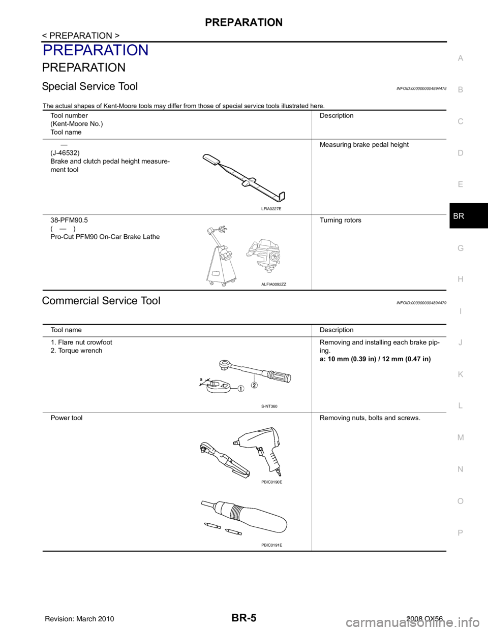
The actual shapes of Kent-Moore tools may differ from those of special service tools illustrated here.
Commercial Service ToolINFOID:0000000004894479
Tool number
(Kent-Moore No.)
Tool name Description
—
(J-46532)
Brake and clutch pedal height measure-
ment tool Measuring brake pedal height
38-PFM90.5
(—)
Pro-Cut PFM90 On-Car Brake Lathe Turning rotors
LFIA0227E
ALFIA0092ZZ
Tool name
Description
1. Flare nut crowfoot
2. Torque wrench Removing and installing each brake pip-
ing.
a: 10 mm (0.39 in) / 12 mm (0.47 in)
Power tool Removing nuts, bolts and screws.
S-NT360
PBIC0190E
PBIC0191E
Revision: March 2010 2008 QX56
Page 435 of 4083
BRAKE PEDALBR-15
< ON-VEHICLE MAINTENANCE >
C
DE
G H
I
J
K L
M A
B
BR
N
O P
ON-VEHICLE MAINTENANCE
BRAKE PEDAL
Inspection and AdjustmentINFOID:0000000004894492
INSPECTION
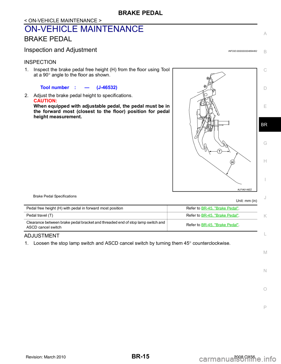
1. Inspect the brake pedal free height (H) from the floor using Tool at a 90 ° angle to the floor as shown.
2. Adjust the brake pedal height to specifications. CAUTION:
When equipped with adjustable pedal, the pedal must be in
the forward most (closest to th e floor) position for pedal
height measurement.
Brake Pedal Specifications
Unit: mm (in)
ADJUSTMENT
1. Loosen the stop lamp switch and ASCD cancel switch by turning them 45° counterclockwise.
Tool number : — (J-46532)
ALFIA0149ZZ
Pedal free height (H) with pedal in forward most position
Refer to BR-45, "Brake Pedal".
Pedal travel (T) Refer to BR-45, "
Brake Pedal".
Clearance between brake pedal bracket and threaded end of stop lamp switch and
ASCD cancel switch Refer to
BR-45, "
Brake Pedal".
Revision: March 2010 2008 QX56
Page 436 of 4083
BR-16
< ON-VEHICLE MAINTENANCE >
BRAKE PEDAL
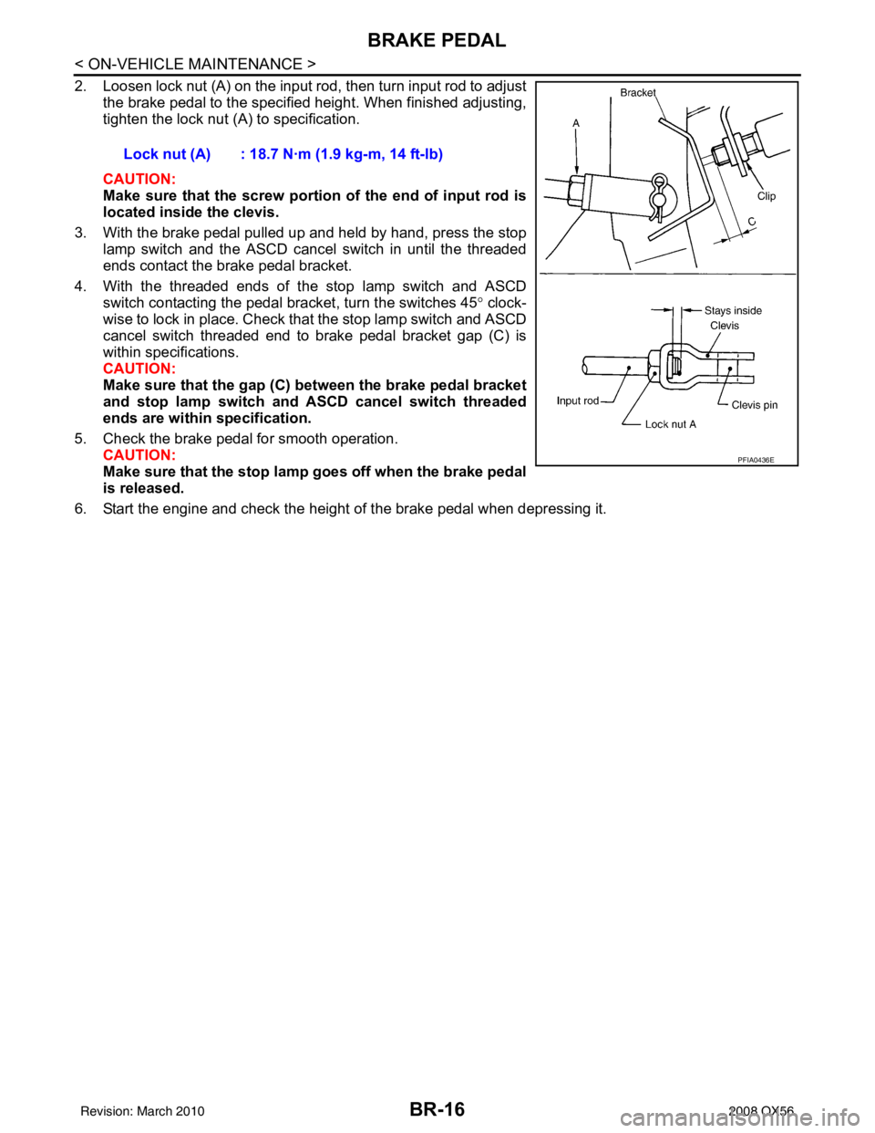
2. Loosen lock nut (A) on the input rod, then turn input rod to adjustthe brake pedal to the specified height. When finished adjusting,
tighten the lock nut (A) to specification.
CAUTION:
Make sure that the screw portion of the end of input rod is
located inside the clevis.
3. With the brake pedal pulled up and held by hand, press the stop lamp switch and the ASCD cancel switch in until the threaded
ends contact the brake pedal bracket.
4. With the threaded ends of the stop lamp switch and ASCD switch contacting the pedal bracket, turn the switches 45 ° clock-
wise to lock in place. Check that the stop lamp switch and ASCD
cancel switch threaded end to brake pedal bracket gap (C) is
within specifications.
CAUTION:
Make sure that the gap (C) between the brake pedal bracket
and stop lamp switch and ASCD cancel switch threaded
ends are within specification.
5. Check the brake pedal for smooth operation. CAUTION:
Make sure that the stop lamp goes off when the brake pedal
is released.
6. Start the engine and check the height of the brake pedal when depressing it. Lock nut (A) : 18.7 N·m (1.9 kg-m, 14 ft-lb)
PFIA0436E
Revision: March 2010
2008 QX56
Page 447 of 4083
BRAKE BOOSTERBR-27
< ON-VEHICLE REPAIR >
C
DE
G H
I
J
K L
M A
B
BR
N
O P
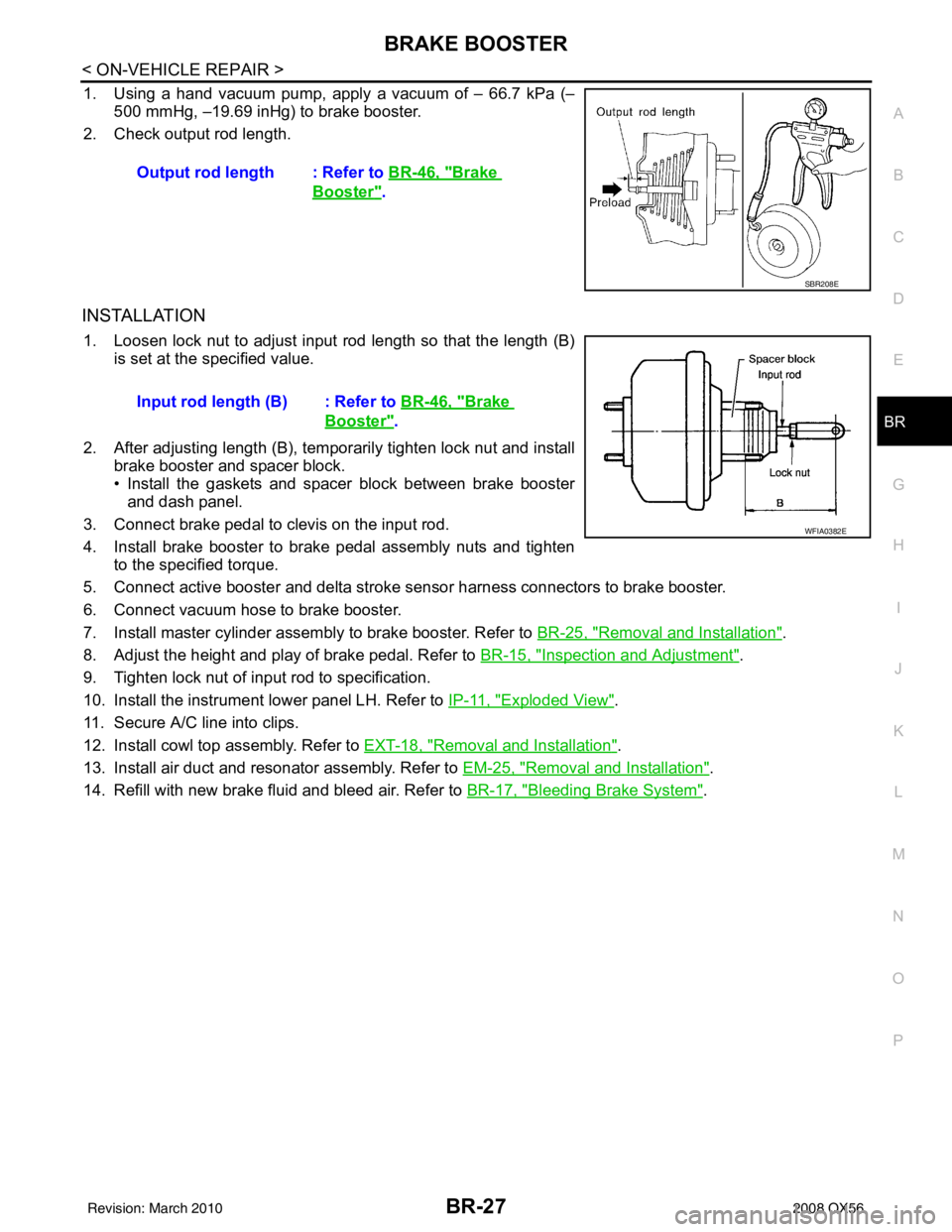
1. Using a hand vacuum pump, apply a vacuum of – 66.7 kPa (– 500 mmHg, –19.69 inHg) to brake booster.
2. Check output rod length.
INSTALLATION
1. Loosen lock nut to adjust input r od length so that the length (B)
is set at the specified value.
2. After adjusting length (B), temporarily tighten lock nut and install brake booster and spacer block.
• Install the gaskets and spacer block between brake boosterand dash panel.
3. Connect brake pedal to clevis on the input rod.
4. Install brake booster to brake pedal assembly nuts and tighten to the specified torque.
5. Connect active booster and delta stroke s ensor harness connectors to brake booster.
6. Connect vacuum hose to brake booster.
7. Install master cylinder assembly to brake booster. Refer to BR-25, "
Removal and Installation".
8. Adjust the height and play of brake pedal. Refer to BR-15, "
Inspection and Adjustment".
9. Tighten lock nut of input rod to specification.
10. Install the instrument lower panel LH. Refer to IP-11, "
Exploded View".
11. Secure A/C line into clips.
12. Install cowl top assembly. Refer to EXT-18, "
Removal and Installation".
13. Install air duct and resonator assembly. Refer to EM-25, "
Removal and Installation".
14. Refill with new brake fluid and bleed air. Refer to BR-17, "
Bleeding Brake System".
Output rod length : Refer to
BR-46, "
Brake
Booster".
SBR208E
Input rod length (B) : Refer to BR-46, "Brake
Booster".
WFIA0382E
Revision: March 2010 2008 QX56
Page 465 of 4083
SERVICE DATA AND SPECIFICATIONS (SDS)BR-45
< SERVICE DATA AND SPECIFICATIONS (SDS)
C
DE
G H
I
J
K L
M A
B
BR
N
O P
SERVICE DATA AND SPECIFICATIONS (SDS)
SERVICE DATA AND SPECIFICATIONS (SDS)
General SpecificationINFOID:0000000004894499
Unit: mm (in)
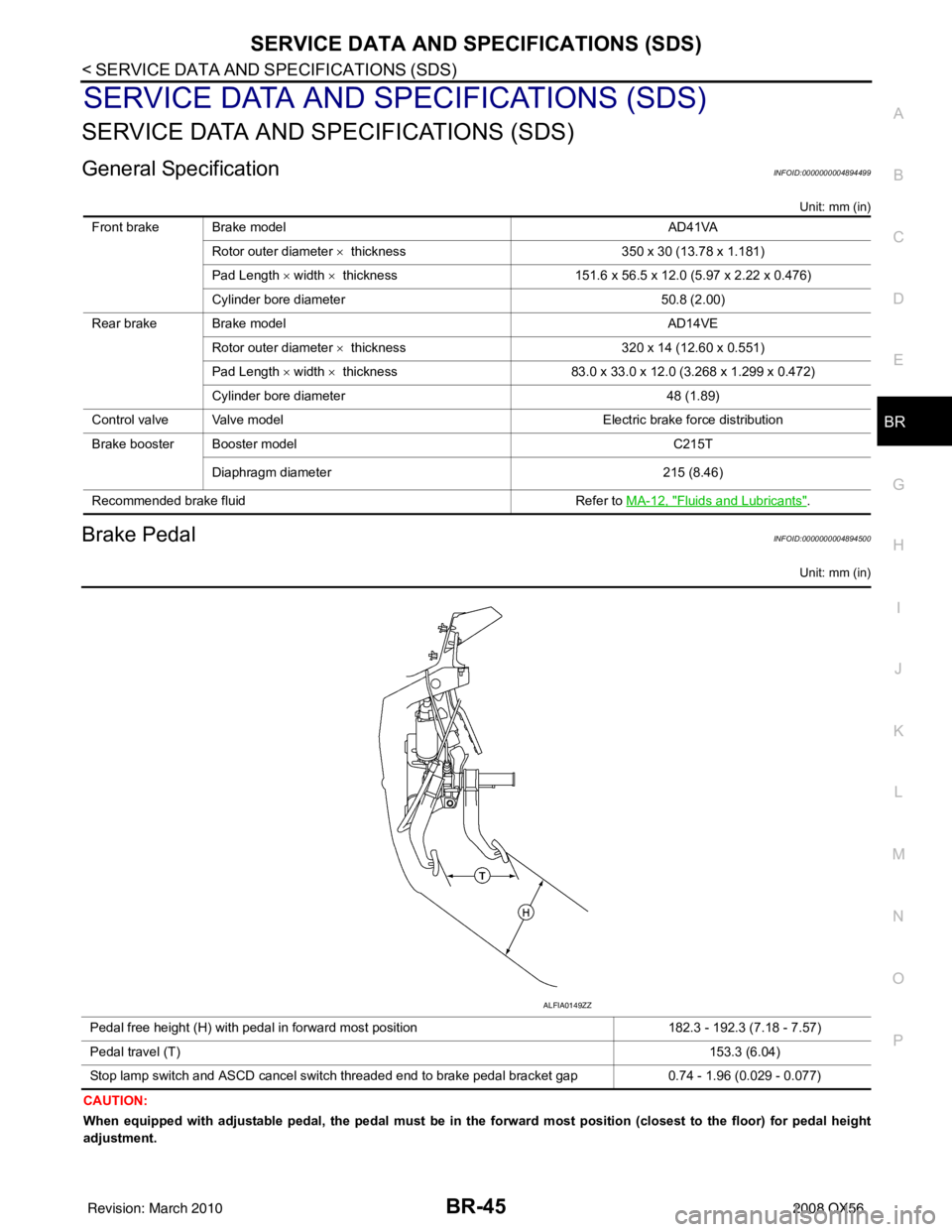
Brake PedalINFOID:0000000004894500
Unit: mm (in)
CAUTION:
When equipped with adjustable pedal, the pedal must be in the forward most position (closest to the floor) for pedal height
adjustment. Front brake Brake model
AD41VA
Rotor outer diameter × thickness 350 x 30 (13.78 x 1.181)
Pad Length × width × thickness 151.6 x 56.5 x 12.0 (5.97 x 2.22 x 0.476)
Cylinder bore diameter 50.8 (2.00)
Rear brake Brake model AD14VE
Rotor outer diameter × thickness 320 x 14 (12.60 x 0.551)
Pad Length × width × thickness 83.0 x 33.0 x 12.0 (3.268 x 1.299 x 0.472)
Cylinder bore diameter 48 (1.89)
Control valve Valve model Electric brake force distribution
Brake booster Booster model C215T
Diaphragm diameter 215 (8.46)
Recommended brake fluid Refer to MA-12, "
Fluids and Lubricants".
Pedal free height (H) with pedal in forward most position 182.3 - 192.3 (7.18 - 7.57)
Pedal travel (T) 153.3 (6.04)
Stop lamp switch and ASCD cancel switch threaded end to brake pedal bracket gap 0.74 - 1.96 (0.029 - 0.077)
ALFIA0149ZZ
Revision: March 2010 2008 QX56
Page 645 of 4083
CCS
INSPECTION AND ADJUSTMENTCCS-5
< BASIC INSPECTION >
C
DE
F
G H
I
J
K L
M B
N P A
INSPECTION AND ADJUSTMENT
ADDITIONAL SERVICE WHEN REPLACING CONTROL UNIT
ADDITIONAL SERVICE WHEN REPL ACING CONTROL UNIT : Description
INFOID:0000000001731800
Always perform the laser beam aiming adjustment after repl acing the ICC unit. In addition, test the ICC sys-
tem operations to see if it functions normally.
ADDITIONAL SERVICE WHEN REPLACING CONTROL UNIT : Special Repair Re-
quirement
INFOID:0000000001731801
1.LASER BEAM AIMING ADJUSTMENT
Adjust laser beam aiming. Refer to CCS-5, "
LASER BEAM AIMING ADJUSTMENT : Outline of Laser Beam
Aiming Adjustment Procedure".
>> GO TO 2
2.ICC SYSTEM ACTION TEST
1. Perform the ICC system operation test. Refer to CCS-8, "
ACTION TEST : ICC System Running Test".
2. Check that the ICC system operates normally.
>> INSPECTION END.
LASER BEAM AIMI NG ADJUSTMENT
LASER BEAM AIMING ADJUSTMENT : Outlin e of Laser Beam Aiming Adjustment
Procedure
INFOID:0000000001756724
CAUTION:
• The laser beam aiming adjustment can not be performed without CONSULT-III.
• The laser beam aiming adjustment must be performed every time the ICC sensor is removed,
installed or has been moved as a result of a collision.
1. Prepare the vehicle and the work area.
2. Set up the ICC target board. For details, refer to Technical Service Bulletin.
3. Adjust the sensor following the procedure on CONSULT-III.
4. Check system operation after the adjustment.
LASER BEAM AIMING ADJU STMENT : PreparationINFOID:0000000001756725
• Place the vehicle on level ground. Shift the transmi ssion into "P" position and release the parking brake.
• Adjust the tire pressure to the specified value.
• See that there is no load in the vehicle. Coolant , engine oil and fuel should be filled to correct level.
• Check that the vehicle suspension has been adjusted to the standard height by the load leveling rear air sus-
pension system. Refer to SCS-7, "
CONSULT-III Function" .
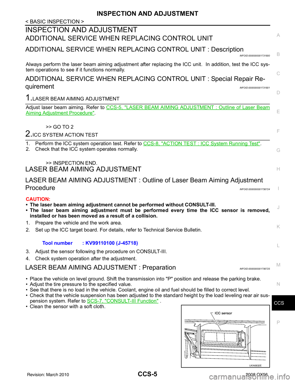
• Clean the sensor with a soft cloth. Tool number : KV99110100 (J-45718)
LKIA0632E
Revision: March 2010
2008 QX56
Page 646 of 4083
CCS-6
< BASIC INSPECTION >
INSPECTION AND ADJUSTMENT
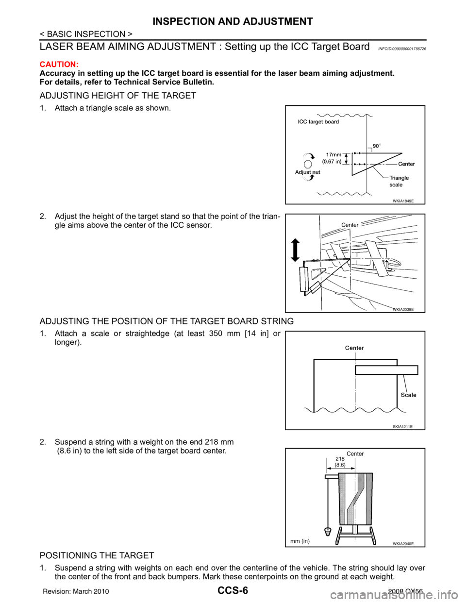
LASER BEAM AIMING ADJUSTMENT : Setting up the ICC Target Board
INFOID:0000000001756726
CAUTION:
Accuracy in setting up the ICC target board is essential for the laser beam aiming adjustment.
For details, refer to T echnical Service Bulletin.
ADJUSTING HEIGHT OF THE TARGET
1. Attach a triangle scale as shown.
2. Adjust the height of the target stand so that the point of the trian-
gle aims above the center of the ICC sensor.
ADJUSTING THE POSITION OF THE TARGET BOARD STRING
1. Attach a scale or straightedge (at least 350 mm [14 in] orlonger).
2. Suspend a string with a weight on the end 218 mm (8.6 in) to the left side of the target board center.
POSITIONING THE TARGET
1. Suspend a string with weights on each end over the cent erline of the vehicle. The string should lay over
the center of the front and bac k bumpers. Mark these centerpoi nts on the ground at each weight.
WKIA1849E
WKIA2039E
SKIA1211E
WKIA2040E
Revision: March 2010 2008 QX56