torque INFINITI QX56 2008 Factory Service Manual
[x] Cancel search | Manufacturer: INFINITI, Model Year: 2008, Model line: QX56, Model: INFINITI QX56 2008Pages: 4083, PDF Size: 81.73 MB
Page 173 of 4083

PRECAUTIONSADP-159
< PRECAUTION >
C
DE
F
G H
I
K L
M A
B
ADP
N
O P
5. When the repair work is completed, return the ignition switch to the ″LOCK ″ position before connecting
the battery cables. (At this time, the steering lock mechanism will engage.)
6. Perform a self-diagnosis check of al l control units using CONSULT-III.
Precaution for WorkINFOID:0000000001537294
• When removing or disassembling each component, be ca reful not to damage or deform it. If a component
may be subject to interference, be sure to protect it with a shop cloth.
• When removing (disengaging) components with a screwdriver or similar tool, be sure to wrap the component
with a shop cloth or vinyl tape to protect it.
• Protect the removed parts with a shop cloth and keep them.
• Replace a deformed or damaged clip.
• If a part is specified as a non-reusable part, always replace it with new one.
• Be sure to tighten bolts and nuts securely to the specified torque.
• After re-installation is completed, be sure to check that each part works normally.
• Follow the steps below to clean components.
- Water soluble foul: Dip a soft cloth into lukewarm water, and wring the water out of the cloth to wipe the fouled area.
Then rub with a soft and dry cloth.
- Oily foul: Dip a soft cloth into lukewarm water with mild detergent (concentration: within 2 to 3%), and wipe the fouled area.
Then dip a cloth into fresh water, and wring the water out of the cloth to wipe the detergent off. Then rub with
a soft and dry cloth.
• Do not use organic solvent such as thinner, benzene, alcohol, or gasoline.
• For genuine leather seats, use a genuine leather seat cleaner.
Revision: March 2010 2008 QX56
Page 424 of 4083

BR-4
< PRECAUTION >
PRECAUTIONS
5. When the repair work is completed, return the ignition switch to the ″LOCK ″ position before connecting
the battery cables. (At this time, the steering lock mechanism will engage.)
6. Perform a self-diagnosis check of a ll control units using CONSULT-III.
Precaution for Brake SystemINFOID:0000000001604475
• Always use recommended brake fluid. Refer to MA-12, "Fluids and Lubricants".
• Do not reuse drained brake fluid.
• Be careful not to splash brake fluid on painted areas.
• To clean or wash all parts of master cylinder, disc brake caliper and wheel cylinder, use clean brake fluid.
• Do not use mineral oils such as gasoline or kerosene. They will ruin rubber parts of the hydraulic system.
• Use flare nut wrench when removing and installing brake tube.
• Always check tightening torque when installing brake lines.
• Before working, turn ignition switch to OFF and disconnect con- nectors for ABS actuator and electric unit (control unit) or battery
terminals.
• Burnish the brake contact surfaces after refinishing or replacing drums or rotors, after replacing pads or linings, or if a soft pedal
occurs at very low mileage. Refer to BR-35, "
Brake Burnishing
Procedure".
WARNING:
• Clean brake pads and shoes wi th a waste cloth, then wipe
with a dust collector.
SBR686C
Revision: March 2010 2008 QX56
Page 425 of 4083

PREPARATIONBR-5
< PREPARATION >
C
DE
G H
I
J
K L
M A
B
BR
N
O P
PREPARATION
PREPARATION
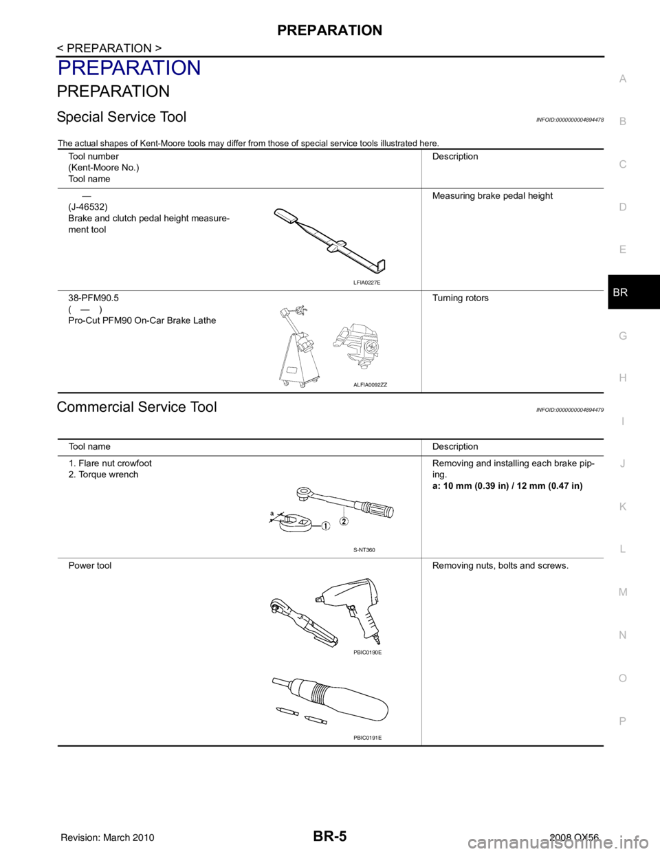
Special Service ToolINFOID:0000000004894478
The actual shapes of Kent-Moore tools may differ from those of special service tools illustrated here.
Commercial Service ToolINFOID:0000000004894479
Tool number
(Kent-Moore No.)
Tool name Description
—
(J-46532)
Brake and clutch pedal height measure-
ment tool Measuring brake pedal height
38-PFM90.5
(—)
Pro-Cut PFM90 On-Car Brake Lathe Turning rotors
LFIA0227E
ALFIA0092ZZ
Tool name
Description
1. Flare nut crowfoot
2. Torque wrench Removing and installing each brake pip-
ing.
a: 10 mm (0.39 in) / 12 mm (0.47 in)
Power tool Removing nuts, bolts and screws.
S-NT360
PBIC0190E
PBIC0191E
Revision: March 2010 2008 QX56
Page 438 of 4083

BR-18
< ON-VEHICLE MAINTENANCE >
BRAKE FLUID
3. Fully depress brake pedal 4 to 5 times.
4. With brake pedal depressed, loosen bleed valve to let the air out, and then tighten it immediately.
5. Repeat steps 3 and 4 until no more air comes out.
6. Tighten bleed valve to the specified torque. Refer to BR-31, "
Exploded View of Brake Caliper" (front disc
brake), BR-35, "
Exploded View of Brake Caliper" (rear disc brake).
7. Repeat steps 2 through 6 at each wheel, with master cylinder reservoir tank filled at least half way, bleed- ing air in order from the front left, rear left, and front right bleed valves.
Revision: March 2010 2008 QX56
Page 447 of 4083

BRAKE BOOSTERBR-27
< ON-VEHICLE REPAIR >
C
DE
G H
I
J
K L
M A
B
BR
N
O P
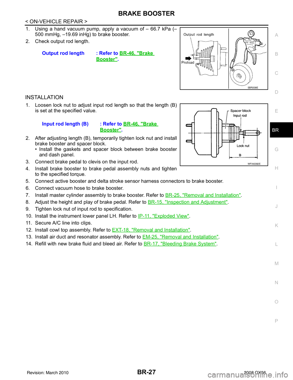
1. Using a hand vacuum pump, apply a vacuum of – 66.7 kPa (– 500 mmHg, –19.69 inHg) to brake booster.
2. Check output rod length.
INSTALLATION
1. Loosen lock nut to adjust input r od length so that the length (B)
is set at the specified value.
2. After adjusting length (B), temporarily tighten lock nut and install brake booster and spacer block.
• Install the gaskets and spacer block between brake boosterand dash panel.
3. Connect brake pedal to clevis on the input rod.
4. Install brake booster to brake pedal assembly nuts and tighten to the specified torque.
5. Connect active booster and delta stroke s ensor harness connectors to brake booster.
6. Connect vacuum hose to brake booster.
7. Install master cylinder assembly to brake booster. Refer to BR-25, "
Removal and Installation".
8. Adjust the height and play of brake pedal. Refer to BR-15, "
Inspection and Adjustment".
9. Tighten lock nut of input rod to specification.
10. Install the instrument lower panel LH. Refer to IP-11, "
Exploded View".
11. Secure A/C line into clips.
12. Install cowl top assembly. Refer to EXT-18, "
Removal and Installation".
13. Install air duct and resonator assembly. Refer to EM-25, "
Removal and Installation".
14. Refill with new brake fluid and bleed air. Refer to BR-17, "
Bleeding Brake System".
Output rod length : Refer to
BR-46, "
Brake
Booster".
SBR208E
Input rod length (B) : Refer to BR-46, "Brake
Booster".
WFIA0382E
Revision: March 2010 2008 QX56
Page 449 of 4083

FRONT DISC BRAKEBR-29
< ON-VEHICLE REPAIR >
C
DE
G H
I
J
K L
M A
B
BR
N
O P
FRONT DISC BRAKE
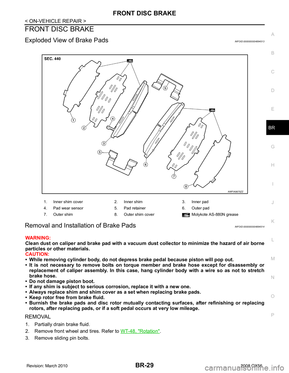
Exploded View of Brake PadsINFOID:0000000004894513
Removal and Installation of Brake PadsINFOID:0000000004894514
WARNING:
Clean dust on caliper and brake pad with a vacuum dust collector to minimize the hazard of air borne
particles or other materials.
CAUTION:
• While removing cylinder bod y, do not depress brake pedal because piston will pop out.
• It is not necessary to remove bolts on torque member and brake hose except for disassembly or replacement of caliper assembly. In this case, hang cylinder body with a wire so as not to stretch
brake hose.
• Do not damage piston boot.
• If any shim is subject to serious corrosion, replace it with a new one.
• Always replace shim and shim cover as a set when replacing brake pads.
• Keep rotor free from brake fluid.
• Burnish the brake pads and disc rotor mutually contacting surfaces, after refinishing or replacing rotors, after replacing pads, or if a so ft pedal occurs at very low mileage.
REMOVAL
1. Partially drain brake fluid.
2. Remove front wheel and tires. Refer to WT-48, "
Rotation".
3. Remove sliding pin bolts.
1. Inner shim cover 2. Inner shim3. Inner pad
4. Pad wear sensor 5. Pad retainer6. Outer pad
7. Outer shim 8. Outer shim cover Molykote AS-880N grease
AWFIA0675ZZ
Revision: March 2010 2008 QX56
Page 450 of 4083

BR-30
< ON-VEHICLE REPAIR >
FRONT DISC BRAKE
4. Hang cylinder body with a wire, and remove pads, pad retainers,shims, and shim cover from torque member.
CAUTION:
When removing the pad retainer from the torque member,
lift it in the direction indi cated by the arrow as shown so
that it does not deform.
INSTALLATION
1. Push piston in using suitable tool.
CAUTION:
In the case of replacing a pad with new one, ch eck the brake fluid level in the reservoir tank
because brake fluid returns to reservoir tank when pressing piston in.
NOTE:
Use a suitable tool to easily press in piston.
2. Apply Molykote AS-880N grease or equivalent to between shim cover and shim. Install inner shim, inner shim cover to inner pad, and install outer shim, outer shim cover to outer pad.
3. Install pad retainers and pads to torque member. CAUTION:
• Securely assemble pad retainers so that they ar e not being lifted up from torque member.
• Both inner and outer pads have a pad return system on the pad retainer. Install pad return lever
securely to pad wear sensor.
4. Install cylinder body to torque member.
5. Install sliding pin bolts, and tighten to specified torque. Refer to BR-31, "
Exploded View of Brake Caliper".
6. Check front disc brake for drag and correct as necessary.
7. Install front wheel and tire. Refer to WT-48, "
Rotation".
8. Check brake fluid level. Refer to BR-17, "
On Board Inspection".
Brake Burnishing ProcedureINFOID:0000000004894515
Burnish contact surfaces between disc rotors and pads according to following procedure after refinishing or
replacing rotors, after replacing pads, or if a soft pedal occurs at very low mileage.
CAUTION:
• Be careful of vehicle speed because the brake does not operate easily until pad and disc rotor are securely seated.
• Only perform this procedure under safe road and traffic conditions. Use extreme caution.
1. Drive vehicle on straight, flat road.
2. Depress brake pedal with the power to stop vehicle within 3 to 5 seconds until the vehicle stops.
3. Drive without depressing brake for a few minutes to cool the brake.
4. Repeat steps 1 through 3 until pad and disc rotor are securely seated.
SBR556E
Revision: March 2010 2008 QX56
Page 451 of 4083

FRONT DISC BRAKEBR-31
< ON-VEHICLE REPAIR >
C
DE
G H
I
J
K L
M A
B
BR
N
O P
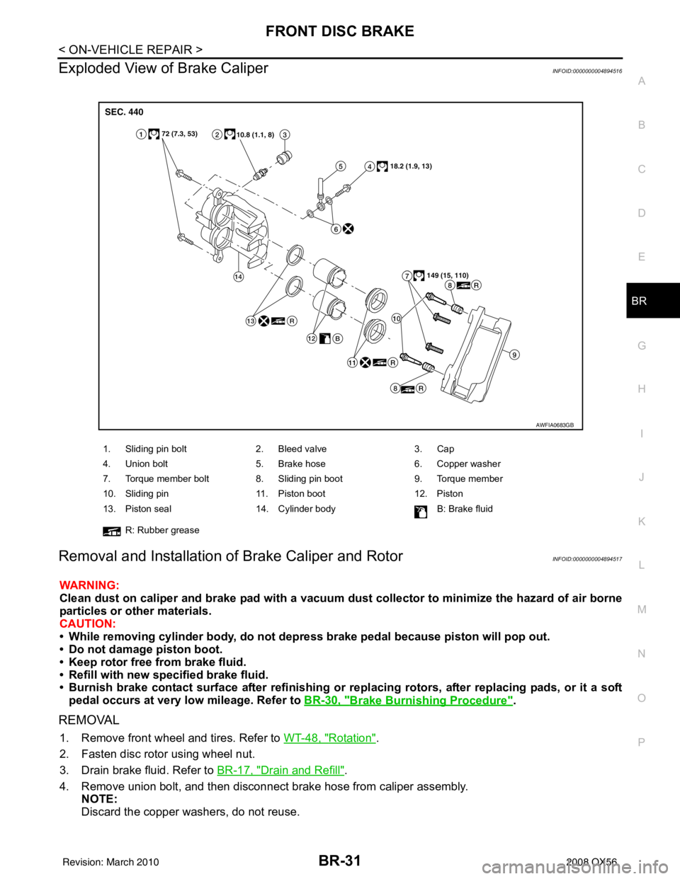
Exploded View of Brake CaliperINFOID:0000000004894516
Removal and Installation of Brake Caliper and RotorINFOID:0000000004894517
WARNING:
Clean dust on caliper and brake pad with a vacuum dust collector to minimize the hazard of air borne
particles or other materials.
CAUTION:
• While removing cylinder bod y, do not depress brake pedal because piston will pop out.
• Do not damage piston boot.
• Keep rotor free from brake fluid.
• Refill with new specified brake fluid.
• Burnish brake contact surface after refinishing or replacing rotors, after replacing pads, or it a soft
pedal occurs at very low mileage. Refer to BR-30, "
Brake Burnishing Procedure".
REMOVAL
1. Remove front wheel and tires. Refer to WT-48, "Rotation".
2. Fasten disc rotor using wheel nut.
3. Drain brake fluid. Refer to BR-17, "
Drain and Refill".
4. Remove union bolt, and then disconnect brake hose from caliper assembly. NOTE:
Discard the copper washers, do not reuse.
1. Sliding pin bolt 2. Bleed valve 3. Cap
4. Union bolt 5. Brake hose 6. Copper washer
7. Torque member bolt 8. Sliding pin boot 9. Torque member
10. Sliding pin 11. Piston boot 12. Piston
13. Piston seal 14. Cylinder body B: Brake fluid
R: Rubber grease
AWFIA0683GB
Revision: March 2010 2008 QX56
Page 452 of 4083

BR-32
< ON-VEHICLE REPAIR >
FRONT DISC BRAKE
5. Remove torque member bolts, and remove brake caliperassembly.
CAUTION:
Do not drop brake pad.
6. Apply matching marks to disc rotor and wheel hub assembly as shown if the disc rotor is to be reused, then remove disc rotor.
CAUTION:
Put matching marks on wheel hub assembly and disc rotor
if the disc rotor is to be reused.
INSTALLATION
1. If reusing the disc rotor, use the matching marks to align discrotor on the wheel hub assembly as shown, then install disc
rotor using a wheel nut to hold it in place.
CAUTION:
Use matching marks on wheel hub assembly and disc rotor
if the disc rotor is to be reused.
2. Install brake caliper assembly to vehicle, and tighten torque member bolts to the specified torque.
CAUTION:
Do not allow oil or any moisture on all contact surfaces
between steering knuckle and caliper assembly, bolts, and
washer.
SFIA2437E
SDIA2608E
SDIA2608E
SFIA2437E
Revision: March 2010 2008 QX56
Page 453 of 4083

FRONT DISC BRAKEBR-33
< ON-VEHICLE REPAIR >
C
DE
G H
I
J
K L
M A
B
BR
N
O P
3. Install brake hose to brake caliper assembly using new copper washers. Align the brake hose to the projection as shown and
tighten union bolts to the specified torque.
CAUTION:
• Do not reuse copper washers.
• Securely attach brake hose to projection on cylinderbody.
4. Refill with new brake fluid and bleed air. Refer to BR-17, "
Bleeding Brake System".
5. Check front disc brake for drag and correct as necessary.
6. Install front wheel and tires. Refer to WT-48, "
Rotation".
SFIA2431E
Revision: March 2010 2008 QX56