coolant INFINITI QX56 2009 Factory Service Manual
[x] Cancel search | Manufacturer: INFINITI, Model Year: 2009, Model line: QX56, Model: INFINITI QX56 2009Pages: 4171, PDF Size: 84.65 MB
Page 2193 of 4171
SERVICE DATA AND SPECIFICATIONS (SDS)FSU-23
< SERVICE DATA AND SPECIFICATIONS (SDS)
C
DF
G H
I
J
K L
M A
B
FSU
N
O P
SERVICE DATA AND SPECIFICATIONS (SDS)
SERVICE DATA AND SPECIFICATIONS (SDS)
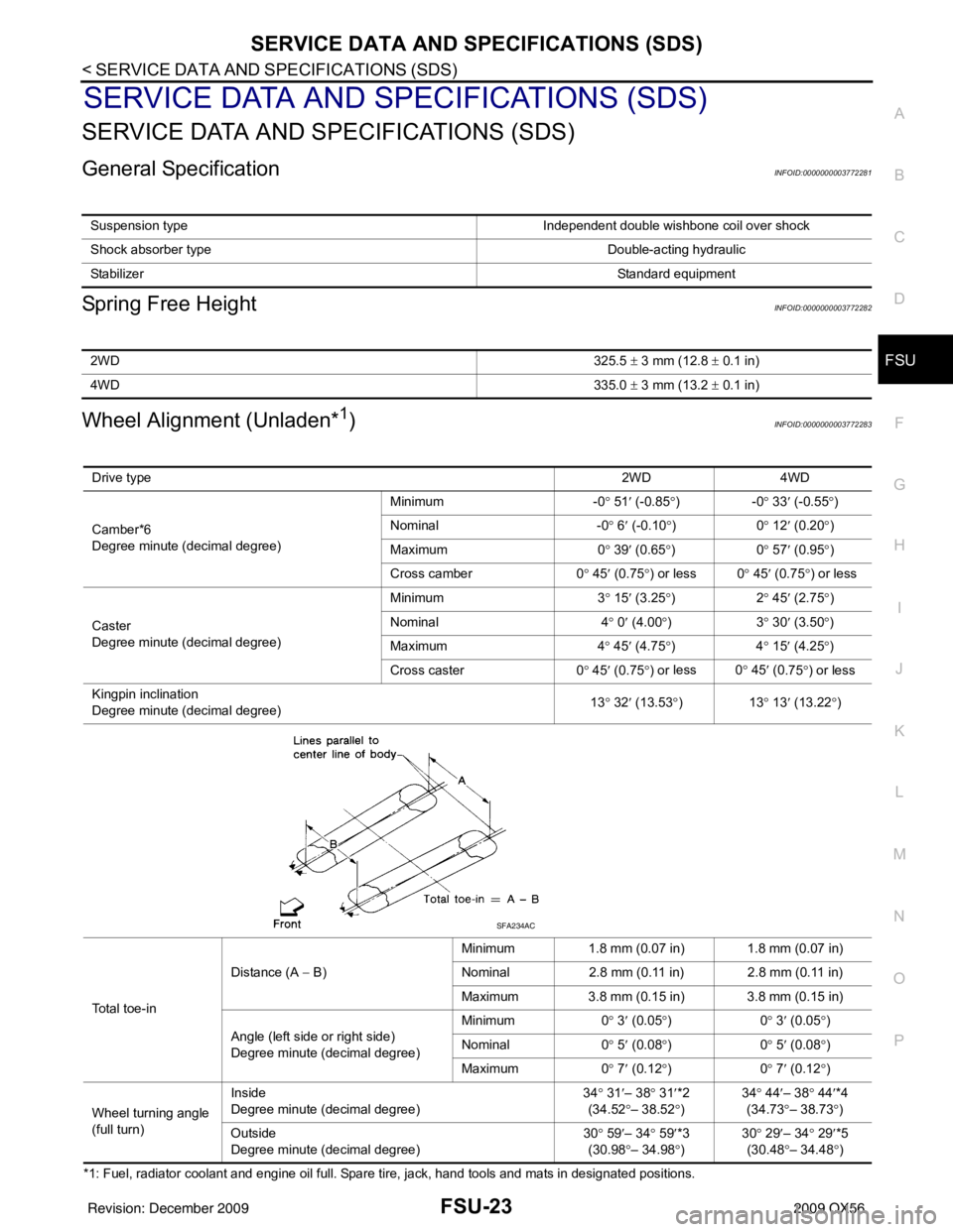
General SpecificationINFOID:0000000003772281
Spring Free HeightINFOID:0000000003772282
Wheel Alignment (Unladen*1)INFOID:0000000003772283
*1: Fuel, radiator coolant and engine oil full. Spare tire, jack, hand tools and mats in designated positions. Suspension type
Independent double wishbone coil over shock
Shock absorber type Double-acting hydraulic
Stabilizer Standard equipment
2WD325.5 ± 3 mm (12.8 ± 0.1 in)
4WD 335.0 ± 3 mm (13.2 ± 0.1 in)
Drive type 2WD 4WD
Camber*6
Degree minute (decimal degree) Minimum
-0° 51 ′ (-0.85 °)- 0° 33 ′ (-0.55 °)
Nominal -0° 6 ′ (-0.10 °)0 ° 12 ′ (0.20 °)
Maximum 0° 39 ′ (0.65 °)0 ° 57 ′ (0.95 °)
Cross camber 0° 45 ′ (0.75 °) or less 0 ° 45′ (0.75 °) or less
Caster
Degree minute (decimal degree) Minimum
3° 15 ′ (3.25 °)2 ° 45 ′ (2.75 °)
Nominal 4° 0 ′ (4.00 °)3 ° 30 ′ (3.50 °)
Maximum 4° 45 ′ (4.75 °)4 ° 15 ′ (4.25 °)
Cross caster 0° 45 ′ (0.75 °) or less 0
° 45 ′ (0
.75°) or less
Kingpin inclination
Degree minute (decimal degree) 13
° 32 ′ (13.53 °)1 3° 13 ′ (13.22 °)
Total toe-in Distance (A
− B) Minimum
1.8 mm (0.07 in) 1.8 mm (0.07 in)
Nominal 2.8 mm (0.11 in) 2.8 mm (0.11 in)
Maximum 3.8 mm (0.15 in) 3.8 mm (0.15 in)
Angle (left side or right side)
Degree minute (decimal degree) Minimum
0° 3 ′ (0.05 °)0 ° 3 ′ (0.05 °)
Nominal 0° 5 ′ (0.08 °)0 ° 5 ′ (0.08 °)
Maximum 0° 7 ′ (0.12 °)0 ° 7 ′ (0.12 °)
Wheel turning angle
(full turn) Inside
Degree minute (decimal degree)
34
° 31 ′– 38 ° 31 ′*2
(34.52 °– 38.52° ) 34
° 44 ′– 38° 44′*4
(34.73 °– 38.73 °)
Ou t
side
Degree minute (decimal degree) 30
° 59 ′– 34 ° 59 ′*3
(30.98 °– 34.98° ) 30
° 29 ′– 34° 29′*5
(30.48 °– 34.48 °)
SFA234AC
Revision: December 20092009 QX56
Page 2194 of 4171
FSU-24
< SERVICE DATA AND SPECIFICATIONS (SDS)
SERVICE DATA AND SPECIFICATIONS (SDS)
*2: Target value 37° 31 ′ (37.52 °)
*3: Target value 33 ° 59 ′ (33.98 °)
*4: Target value 37 ° 44 ′ (37.73 °)
*5: Target value 33 ° 29 ′ (33.48 °)
*6 Some vehicles may not be equipped with straight (non-adjustable) lower link bolts and washers. In order to adjust camber and caster
on these vehicles, first replace the lower link bolts and washers with adjustable (cam) bolts and washers
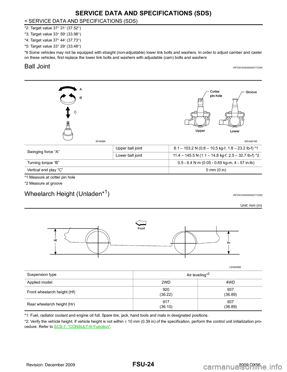
Ball JointINFOID:0000000003772284
*1 Measure at cotter pin hole
*2 Measure at groove
Wheelarch Height (Unladen*1)INFOID:0000000003772285
Unit: mm (in)
*1: Fuel, radiator coolant and engine oil full. Spare tire, jack, hand tools and mats in designated positions.
*2: Verify the vehicle height. If vehicle height is not within ± 10 mm (0.39 in) of the specification, perform the control unit initialization pro-
cedure. Refer to SCS-7, "
CONSULT-III Function".
Swinging force “A”
Upper ball joint
8.1 – 103.2 N (0.8 – 10.5 kg-f, 1.8 – 23.2 lb-f) *1
Lower ball joint 11.4 – 145.5 N (1.1 – 14.8 kg-f, 2.5 – 32.7 lb-f) *2
Turning torque “B” 0.5 - 6.4 N·m (0.05 - 0.65 kg-m, 4 - 57 in-lb)
Vertical end play “C” 0 mm (0 in)
SFA858AWEIA0076E
Suspension type
Air leveling*2
Applied model2WD4WD
Front wheelarch height (Hf) 920
(36.22) 937
(36.89)
Rear wheelarch height (Hr) 917
(36.10) 937
(36.89)
LEIA0085E
Revision: December 20092009 QX56
Page 2210 of 4171

GI-16
< HOW TO USE THIS MANUAL >
TERMINOLOGY
TERMINOLOGY
SAE J1930 Terminology ListINFOID:0000000003771188
All emission related terms used in this publication in accordance with SAE J1930 are listed. Accordingly, new
terms, new acronyms/abbreviations and old terms are listed in the following chart.
NEW TERMNEW ACRONYM /
ABBREVIATION OLD TERM
Air cleaner ACL Air cleaner
Barometric pressure BARO ***
Barometric pressure sensor-BCDD BAROS-BCDD BCDD
Camshaft position CMP ***
Camshaft position sensor CMPSCrank angle sensor
Canister *** Canister
Carburetor CARBCarburetor
Charge air cooler CACIntercooler
Closed loop CLClosed loop
Closed throttle position switch CTP switchIdle switch
Clutch pedal position switch CPP switch Clutch switch
Continuous fuel injection system CFI system***
Continuous trap oxidizer system CTOX system ***
Crankshaft position CKP***
Crankshaft position sensor CKPS***
Data link connector DLC***
Data link connector for CONSULT-III DLC for CONSULT-IIIDiagnostic connector for CONSULT-III
Diagnostic test mode DTMDiagnostic mode
Diagnostic test mode selector DTM selectorDiagnostic mode selector
Diagnostic test mode I DTM I Mode I
Diagnostic test mode II DTM IIMode II
Diagnostic trouble code DTCMalfunction code
Direct fuel injection system DFI system ***
Distributor ignition system DI system Ignition timing control
Early fuel evaporation-mixture heater EFE-mixture heater Mixture heater
Early fuel evaporation system EFE system Mixture heater control
Electrically erasable programmable read
only memory EEPROM
***
Electronic ignition system EI systemIgnition timing control
Engine control EC ***
Engine control module ECM ECCS control unit
Engine coolant temperature ECT Engine temperature
Engine coolant temperature sensor ECTS Engine temperature sensor
Engine modification EM ***
Engine speed RPM Engine speed
Erasable programmable read only memory EPROM ***
Evaporative emission canister EVAP canister Canister
Evaporative emission system EVAP system Canister control solenoid valve
Exhaust gas recirculation valve EGR valve EGR valve
Revision: December 20092009 QX56
Page 2301 of 4171
LOW-PRESSURE PIPEHA-37
< ON-VEHICLE REPAIR >
C
DE
F
G H
J
K L
M A
B
HA
N
O P
LOW-PRESSURE PIPE
Removal and Installation for Low-Pressure PipeINFOID:0000000003775312
REMOVAL
1. Discharge the refrigerant. Refer to HA-20, "HFC-134a (R-134a) Service Procedure".
2. Remove the cowl top and the cowl top extension. Refer to EXT-18, "Removal and Installation"
.
3. Remove the low-pressure pipe. CAUTION:
Cap or wrap the joint of the pipes with suitable material such as viny l tape to avoid the entry of air.
INSTALLATION
Installation is in the reverse order of removal.
Refer to HA-29, "Component"
.
CAUTION:
Replace the O-ring of the high/low-pressure pipe with a new one, then apply compressor oil to it
when installing it.
After charging refrigerant, check for leaks.
Removal and Installation for Rear High- and Low-Pressure A/C and Heater Core Pipes
INFOID:0000000003775313
REMOVAL
1. Discharge the refrigerant from the A/C system. Refer to HA-20, "HFC-134a (R-134a) Service Procedure".
2. Drain the coolant from the engine cooling system. Refer to CO-11, "Changing Engine Coolant"
.
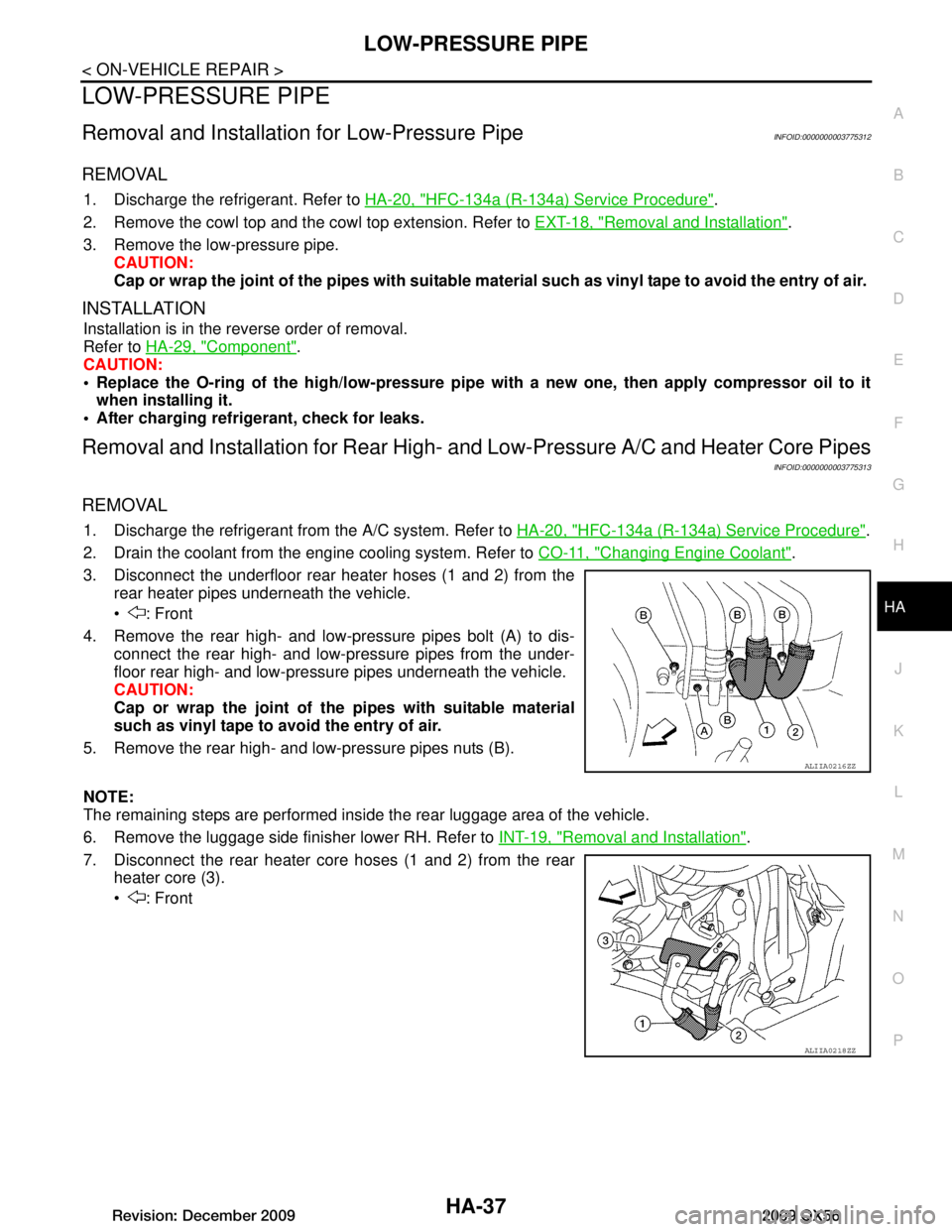
3. Disconnect the underfloor rear heater hoses (1 and 2) from the rear heater pipes underneath the vehicle.
: Front
4. Remove the rear high- and low-pressure pipes bolt (A) to dis- connect the rear high- and low-pressure pipes from the under-
floor rear high- and low-pressu re pipes underneath the vehicle.
CAUTION:
Cap or wrap the joint of the pipes with suitable material
such as vinyl tape to avoid the entry of air.
5. Remove the rear high- and low-pressure pipes nuts (B).
NOTE:
The remaining steps are performed inside the rear luggage area of the vehicle.
6. Remove the luggage side finisher lower RH. Refer to INT-19, "Removal and Installation"
.
7. Disconnect the rear heater core hoses (1 and 2) from the rear heater core (3).
: Front
ALIIA0216ZZ
ALIIA0218ZZ
Revision: December 20092009 QX56
Page 2302 of 4171
HA-38
< ON-VEHICLE REPAIR >
LOW-PRESSURE PIPE
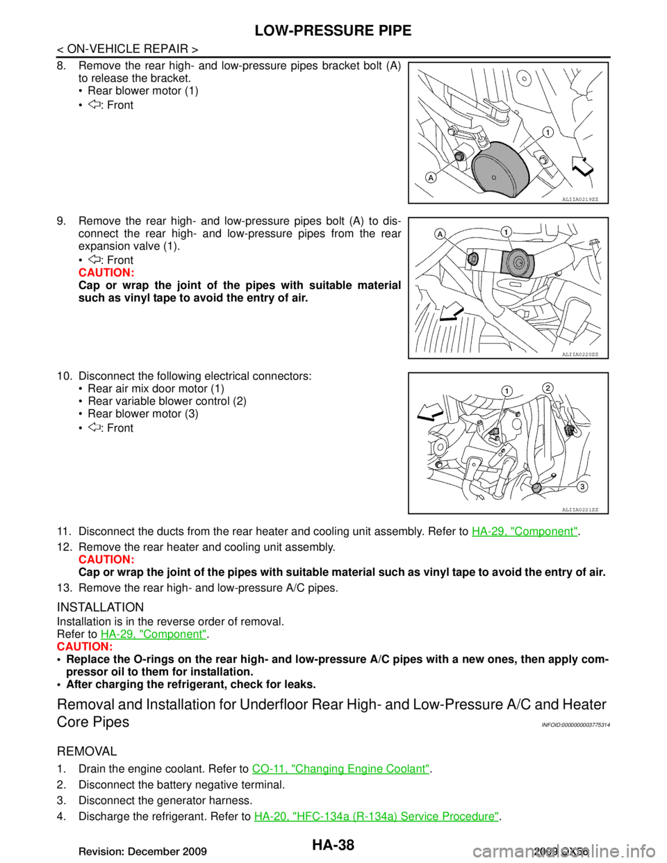
8. Remove the rear high- and low-pressure pipes bracket bolt (A)to release the bracket.
Rear blower motor (1)
: Front
9. Remove the rear high- and low-pressure pipes bolt (A) to dis- connect the rear high- and low-pressure pipes from the rear
expansion valve (1).
: Front
CAUTION:
Cap or wrap the joint of the pipes with suitable material
such as vinyl tape to avoid the entry of air.
10. Disconnect the following electrical connectors: Rear air mix door motor (1)
Rear variable blower control (2)
Rear blower motor (3)
: Front
11. Disconnect the ducts from the rear heater and cooling unit assembly. Refer to HA-29, "Component"
.
12. Remove the rear heater and cooling unit assembly. CAUTION:
Cap or wrap the joint of the pipes with suitable material such as viny l tape to avoid the entry of air.
13. Remove the rear high- and low-pressure A/C pipes.
INSTALLATION
Installation is in the reverse order of removal.
Refer to HA-29, "Component"
.
CAUTION:
Replace the O-rings on the rear high- and low-pr essure A/C pipes with a new ones, then apply com-
pressor oil to them for installation.
After charging the refrigerant, check for leaks.
Removal and Installation for Underfloor Rear High- and Lo w-Pressure A/C and Heater
Core Pipes
INFOID:0000000003775314
REMOVAL
1. Drain the engine coolant. Refer to CO-11, "Changing Engine Coolant".
2. Disconnect the battery negative terminal.
3. Disconnect the generator harness.
4. Discharge the refrigerant. Refer to HA-20, "HFC-134a (R-134a) Service Procedure"
.
ALIIA0219ZZ
ALIIA0220ZZ
ALIIA0221ZZ
Revision: December 20092009 QX56
Page 2305 of 4171
HIGH-PRESSURE PIPEHA-41
< ON-VEHICLE REPAIR >
C
DE
F
G H
J
K L
M A
B
HA
N
O P
HIGH-PRESSURE PIPE
Removal and Installation for High-Pressure PipeINFOID:0000000003775316
REMOVAL
1. Remove the cowl top extension. Refer to EXT-18, "Removal and Installation".
2. Disconnect the battery negative termi nal and positive battery terminal.
3. Reposition the IPDM E/R aside.
4. Remove the front left wheel and tire assembly. Refer to MA-29, "Rotation"
.
5. Position aside the front floor insulator.
6. Discharge the refrigerant. Refer to HA-20, "HFC-134a (R-134a) Service Procedure"
.
7. Remove the low pressure pipe. Refer to HA-37, "Removal and Installation for Low-Pressure Pipe"
.
8. Remove the high-pressure pipe. CAUTION:
Cap or wrap the joint of the pipe with suitable mate rial such as vinyl tape to avoid the entry of air.
INSTALLATION
Installation is in the reverse order of removal.
Refer to HA-29, "Component"
.
CAUTION:
Replace the O-ring of the high-pressure pipe with a new one, then apply compressor oil to it when
installing it.
After charging refrigerant, check for leaks.
Removal and Installation for Rear High- and Low-Pressure A/C and Heater Core Pipes
INFOID:0000000003775317
REMOVAL
1. Discharge the refrigerant from the A/C system. Refer to HA-20, "HFC-134a (R-134a) Service Procedure".
2. Drain the coolant from the engine cooling system. Refer to CO-11, "Changing Engine Coolant"
.
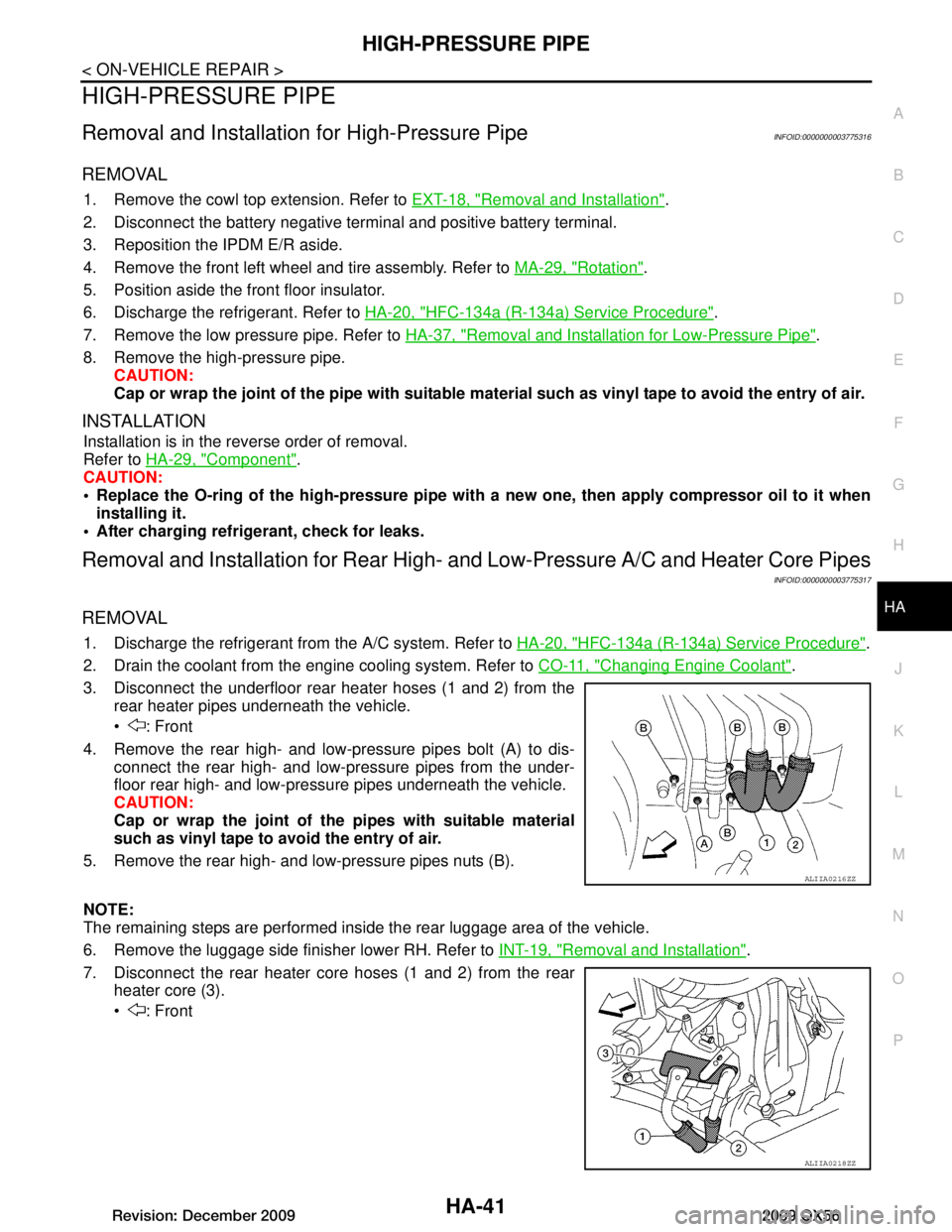
3. Disconnect the underfloor rear heater hoses (1 and 2) from the rear heater pipes underneath the vehicle.
: Front
4. Remove the rear high- and low-pressure pipes bolt (A) to dis- connect the rear high- and low-pressure pipes from the under-
floor rear high- and low-pressu re pipes underneath the vehicle.
CAUTION:
Cap or wrap the joint of the pipes with suitable material
such as vinyl tape to avoid the entry of air.
5. Remove the rear high- and low-pressure pipes nuts (B).
NOTE:
The remaining steps are performed inside the rear luggage area of the vehicle.
6. Remove the luggage side finisher lower RH. Refer to INT-19, "Removal and Installation"
.
7. Disconnect the rear heater core hoses (1 and 2) from the rear heater core (3).
: Front
ALIIA0216ZZ
ALIIA0218ZZ
Revision: December 20092009 QX56
Page 2306 of 4171
HA-42
< ON-VEHICLE REPAIR >
HIGH-PRESSURE PIPE
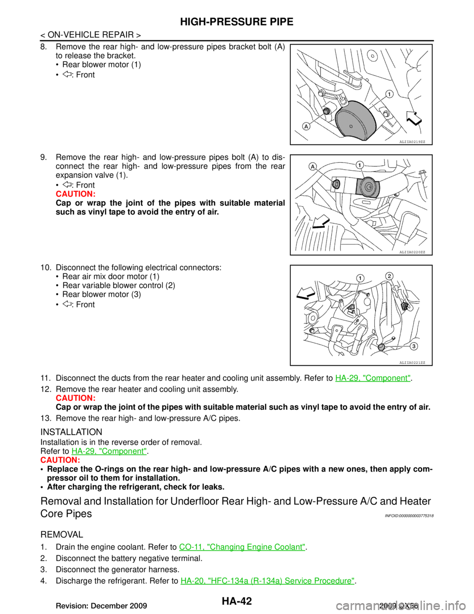
8. Remove the rear high- and low-pressure pipes bracket bolt (A)to release the bracket.
Rear blower motor (1)
: Front
9. Remove the rear high- and low-pressure pipes bolt (A) to dis- connect the rear high- and low-pressure pipes from the rear
expansion valve (1).
: Front
CAUTION:
Cap or wrap the joint of the pipes with suitable material
such as vinyl tape to avoid the entry of air.
10. Disconnect the following electrical connectors: Rear air mix door motor (1)
Rear variable blower control (2)
Rear blower motor (3)
: Front
11. Disconnect the ducts from the rear heater and cooling unit assembly. Refer to HA-29, "Component"
.
12. Remove the rear heater and cooling unit assembly. CAUTION:
Cap or wrap the joint of the pipes with suitable material such as viny l tape to avoid the entry of air.
13. Remove the rear high- and low-pressure A/C pipes.
INSTALLATION
Installation is in the reverse order of removal.
Refer to HA-29, "Component"
.
CAUTION:
Replace the O-rings on the rear high- and low-pr essure A/C pipes with a new ones, then apply com-
pressor oil to them for installation.
After charging the refrigerant, check for leaks.
Removal and Installation for Underfloor Rear High- and Lo w-Pressure A/C and Heater
Core Pipes
INFOID:0000000003775318
REMOVAL
1. Drain the engine coolant. Refer to CO-11, "Changing Engine Coolant".
2. Disconnect the battery negative terminal.
3. Disconnect the generator harness.
4. Discharge the refrigerant. Refer to HA-20, "HFC-134a (R-134a) Service Procedure"
.
ALIIA0219ZZ
ALIIA0220ZZ
ALIIA0221ZZ
Revision: December 20092009 QX56
Page 2363 of 4171
![INFINITI QX56 2009 Factory Service Manual HAC-50
< COMPONENT DIAGNOSIS >[AUTOMATIC AIR CONDITIONER]
BLOWER MOTOR CONTROL SYSTEM
BLOWER MOTOR CONTROL SYSTEM
System DescriptionINFOID:0000000003775356
SYSTEM DESCRIPTION
Component Parts
Blower sp INFINITI QX56 2009 Factory Service Manual HAC-50
< COMPONENT DIAGNOSIS >[AUTOMATIC AIR CONDITIONER]
BLOWER MOTOR CONTROL SYSTEM
BLOWER MOTOR CONTROL SYSTEM
System DescriptionINFOID:0000000003775356
SYSTEM DESCRIPTION
Component Parts
Blower sp](/img/42/57031/w960_57031-2362.png)
HAC-50
< COMPONENT DIAGNOSIS >[AUTOMATIC AIR CONDITIONER]
BLOWER MOTOR CONTROL SYSTEM
BLOWER MOTOR CONTROL SYSTEM
System DescriptionINFOID:0000000003775356
SYSTEM DESCRIPTION
Component Parts
Blower speed control
system components are:• A/C auto amp.
• A/C and AV switch assembly
• Variable blower control
• Front blower motor relay
• Front blower motor
• In-vehicle sensor
• Ambient sensor
• Optical sensor
• Intake sensor
System Operation
Automatic Mode
In the automatic mode, the blower motor speed is calc ulated by the A/C auto amp. and variable blower control
based on input from the in-vehicle sensor, optical sens or, intake sensor and ambient sensor, and potentio tem-
perature control (PTC).
When the air flow is increased, the blower motor s peed is adjusted gradually to prevent a sudden increase in
air flow.
In addition to manual air flow control and the usual automat ic air flow control, starting air flow control, low
water temperature starting control and high passenger compartment temperature starting control are avail-
able.
Starting Blower Speed Control
Start up from cold soak condition (Automatic mode).
In a cold start up condition where the engine coolant temperature is below 50 °C (122° F), the blower will not
operate at blower speed 1 for a short period of time (up to 210 seconds). The exact start delay time varies
depending on the ambient and engine coolant temperatures.
In the most extreme case (very low ambient temper ature) the blower starting delay will be 210 seconds as
described above. After the coolant temperature reaches 50 °C (122° F), or the 210 seconds has elapsed, the
blower speed will increase to the objective blower speed.
Start up from usual operating or hot soak condition (Automatic mode).
The blower will begin operation momentarily after the AUTO switch is pushed. The blower speed will gradually
rise to the objective speed over a time period of 3 seconds or less (actual time depends on the objective
blower speed).
AWIIA0173GB
Revision: December 20092009 QX56
Page 2365 of 4171
![INFINITI QX56 2009 Factory Service Manual HAC-52
< COMPONENT DIAGNOSIS >[AUTOMATIC AIR CONDITIONER]
BLOWER MOTOR CONTROL SYSTEM
YES >> Refer to HAC-24, "A/C System Self-Diagnosis Code Chart".
NO >> GO TO 5.
5.PERFORM A/C AND AV SWITCH ASSEMB INFINITI QX56 2009 Factory Service Manual HAC-52
< COMPONENT DIAGNOSIS >[AUTOMATIC AIR CONDITIONER]
BLOWER MOTOR CONTROL SYSTEM
YES >> Refer to HAC-24, "A/C System Self-Diagnosis Code Chart".
NO >> GO TO 5.
5.PERFORM A/C AND AV SWITCH ASSEMB](/img/42/57031/w960_57031-2364.png)
HAC-52
< COMPONENT DIAGNOSIS >[AUTOMATIC AIR CONDITIONER]
BLOWER MOTOR CONTROL SYSTEM
YES >> Refer to HAC-24, "A/C System Self-Diagnosis Code Chart".
NO >> GO TO 5.
5.PERFORM A/C AND AV SWITCH ASSEMBLY SELF-DIAGNOSIS
Perform self-diagnosis to check the A/C and AV switch assembly. Refer to HAC-23, "
A/C and AV Switch
Assembly Self-Diagnosis".
Is the inspection results normal?
YES >> GO TO 6.
NO >> Replace A/C and AV switch assembly. Refer to VTL-7, "
Removal and Installation".
6.CHECK BLOWER MOTOR OPERATION
Check and verify blower motor operates manually in all speeds.
Does blower motor operate in all speeds?
YES >> GO TO 7.
NO >> Refer to HAC-52, "
Front Blower Motor Diagnosis Procedure".
7.CHECK ENGINE COOLANT TE MPERATURE SENSOR CIRCUIT
Check engine coolant temperature sensor circuit. Refer to EC-121, "
Diagnosis Procedure".
Is the inspection results normal?
YES >> GO TO 8.
NO >> Replace enging coolant temperature sensor.
8.RECHECK FOR ANY SYMPTOMS
Perform a complete operational check for any symptoms. Refer to HAC-4, "
Operational Check (Front)".
Does another symptom exist?
YES >> Refer to HAC-3, "How to Perform Trouble Diagnosis For Quick And Accurate Repair" .
NO >> Replace A/C auto amp. Refer to VTL-7, "
Removal and Installation".
Front Blower Motor Diagnosis ProcedureINFOID:0000000003775358
SYMPTOM: Blower motor operation is malfunctioning.
DIAGNOSTIC PROCEDURE FOR BLOWER MOTOR
SYMPTOM: Blower motor operation is malfunctioning under starting
blower speed control.
1.CHECK FUSES
AWIIA0174GB
Revision: December 20092009 QX56
Page 2390 of 4171
![INFINITI QX56 2009 Factory Service Manual WATER VALVE CIRCUITHAC-77
< COMPONENT DIAGNOSIS > [AUTOMATIC AIR CONDITIONER]
C
D
E
F
G H
J
K L
M A
B
HAC
N
O P
WATER VALVE CIRCUIT
DescriptionINFOID:0000000003775372
COMPONENT DESCRIPTION
Water Valve INFINITI QX56 2009 Factory Service Manual WATER VALVE CIRCUITHAC-77
< COMPONENT DIAGNOSIS > [AUTOMATIC AIR CONDITIONER]
C
D
E
F
G H
J
K L
M A
B
HAC
N
O P
WATER VALVE CIRCUIT
DescriptionINFOID:0000000003775372
COMPONENT DESCRIPTION
Water Valve](/img/42/57031/w960_57031-2389.png)
WATER VALVE CIRCUITHAC-77
< COMPONENT DIAGNOSIS > [AUTOMATIC AIR CONDITIONER]
C
D
E
F
G H
J
K L
M A
B
HAC
N
O P
WATER VALVE CIRCUIT
DescriptionINFOID:0000000003775372
COMPONENT DESCRIPTION
Water Valve
The water valve (1) cuts the flow of engine coolant to the front and
rear heater cores to allow for maximum cooling during A/C opera-
tion. It is controlled by the A/C auto amp.
Water Valve Diagnosis ProcedureINFOID:0000000003775373
DIAGNOSTIC PROCEDURE FOR WATER VALVE
1.CHECK WATER VALVE POWER AND GROUND CIRCUITS
1. Disconnect water valve connector F68.
2. Turn ignition switch ON.
3. Rotate temperature control dial (driver) to 32 °C (90 °F).
4. Check voltage between water valve harness connector F68 ter- minal 1 and terminal 2 while rotating temperature control dial
(driver) to 16 °C (60° F).
Is the inspection result normal?
YES >> GO TO 3.
NO >> GO TO 2.
2.CHECK WATER VALVE CONTROL OUTPUT CIRCUIT
1. Turn ignition switch OFF.
2. Disconnect A/C auto amp. connector M50.
3. Check continuity between water valve harness connector F68 (A) terminal 2 and A/C auto amp. harness connector M50 (B)
terminal 46.
4. Check continuity between water valve harness connector F68 terminal 2 and ground.
Is the inspection result normal?
YES >> Replace A/C auto amp. Refer to VTL-7, "Removal and Installation".
NO >> Repair harness or connector.
3.CHECK WATER VALVE POWER AND GROUND CIRCUITS
WJIA1791E
Connector Te r m i n a l s
Condition Voltage
(Approx.)
(+) (-)
Water valve: F68 2 1Rotate temperature
control dial Battery
voltage
WJIA1794E
2 - 46 : Continuity should exist.
2 - Ground : Continuity should not exist.
AWIIA0203ZZ
Revision: December 20092009 QX56