torque INFINITI QX56 2009 Factory Service Manual
[x] Cancel search | Manufacturer: INFINITI, Model Year: 2009, Model line: QX56, Model: INFINITI QX56 2009Pages: 4171, PDF Size: 84.65 MB
Page 3628 of 4171

SERVICE DATA AND SPECIFICATIONS (SDS)
ST-37
< SERVICE DATA AND SPECIFICATIONS (SDS)
C
D E
F
H I
J
K L
M A
B
ST
N
O P
Inspection After Installation
Steering Outer Socket and Inner SocketINFOID:0000000004187588
Unit: mm (in)
Range “A” 18°
Tilt mechanism range (Manual tilt) 3 ° per notch at 5 steps
WGIA0083E
Tie-rod ball joint outer socket Swinging torque (F) 0.3
− 2.9 N·m (0.03 − 0.29 kg-m, 3 − 25 in-lb)
Measurement on spring balance
Measuring point: cotter pin hole of stud 4.84
− 46.7 N (0.50 − 4.7 kg-f, 4 − 34 lb-f)
Rotating torque 0.3 − 2.9 N·m (0.03 − 0.29 kg-m, 3 − 25 in-lb)
Axial end play 0.5 mm (0.020 in) or less
Tie-rod ball joint inner socket Swinging torque 1.0
− 7.8 N·m (0.11 − 0.79 kg-m, 9 − 69 in-lb)
Measurement on spring balance
Measuring point: L mark see above, L=83.2 mm (3.276 in). 12.1
− 93.7 N (1.3 − 9.5 kg-f, 9 − 69 lb-f)
Axial end play 0.2 mm (0.08 in) or less
SGIA0358E
Inner socket length “L” 102.2 (4.02)
SGIA0167E
Revision: December 20092009 QX56
Page 3650 of 4171

TM-2
On Board Diagnosis Logic ......................................49
Possible Cause .......................................................49
DTC Confirmation Procedure .................................49
Diagnosis Procedure ..............................................50
P0725 ENGINE SPEED .....................................52
Description ........................................................... ...52
CONSULT-III Reference Value in Data Monitor
Mode .................................................................... ...
52
On Board Diagnosis Logic ......................................52
Possible Cause .......................................................52
DTC Confirmation Procedure .................................52
Diagnosis Procedure ..............................................52
P0731 1GR INCORRECT RATIO ......................54
Description ........................................................... ...54
On Board Diagnosis Logic ......................................54
Possible Cause .......................................................54
DTC Confirmation Procedure .................................54
Diagnosis Procedure ..............................................55
P0732 2GR INCORRECT RATIO ......................56
Description ........................................................... ...56
On Board Diagnosis Logic ......................................56
Possible Cause .......................................................56
DTC Confirmation Procedure .................................56
Diagnosis Procedure ..............................................57
P0733 3GR INCORRECT RATIO ......................58
Description ........................................................... ...58
On Board Diagnosis Logic ......................................58
Possible Cause .......................................................58
DTC Confirmation Procedure .................................58
Diagnosis Procedure ..............................................59
P0734 4GR INCORRECT RATIO ......................60
Description ........................................................... ...60
On Board Diagnosis Logic ......................................60
Possible Cause .......................................................60
DTC Confirmation Procedure .................................60
Diagnosis Procedure ..............................................61
P0735 5GR INCORRECT RATIO ......................62
Description ........................................................... ...62
On Board Diagnosis Logic ......................................62
Possible Cause .......................................................62
DTC Confirmation Procedure .................................62
Diagnosis Procedure ..............................................63
P0740 TORQUE CONVERTER .........................64
Description ........................................................... ...64
CONSULT-III Reference Value in Data Monitor
Mode .................................................................... ...
64
On Board Diagnosis Logic ......................................64
Possible Cause .......................................................64
DTC Confirmation Procedure .................................64
Diagnosis Procedure ..............................................64
P0744 TORQUE CONVERTER .........................66
Description ........................................................... ...66
CONSULT-III Reference Value in Data Monitor
Mode .................................................................... ...
66
On Board Diagnosis Logic ......................................66
Possible Cause .......................................................66
DTC Confirmation Procedure ..................................66
Diagnosis Procedure ...............................................67
P0745 PRESSURE CONTROL SOLENOID A ...68
Description ........................................................... ...68
CONSULT-III Reference Value in Data Monitor
Mode .......................................................................
68
On Board Diagnosis Logic ......................................68
Possible Cause .......................................................68
DTC Confirmation Procedure ..................................68
Diagnosis Procedure ...............................................68
P1705 TP SENSOR ...........................................70
Description ........................................................... ...70
CONSULT-III Reference Value in Data Monitor
Mode .......................................................................
70
On Board Diagnosis Logic ......................................70
Possible Cause .......................................................70
DTC Confirmation Procedure ..................................70
Diagnosis Procedure ...............................................70
P1710 TRANSMISSION FLUID TEMPERA-
TURE SENSOR .................................................
72
Description ........................................................... ...72
CONSULT-III Reference Value in Data Monitor
Mode .......................................................................
72
On Board Diagnosis Logic ......................................72
Possible Cause .......................................................72
DTC Confirmation Procedure ..................................72
Diagnosis Procedure ...............................................72
Component Inspection ............................................73
P1721 VEHICLE SPEED SIGNAL ....................74
Description ........................................................... ...74
CONSULT-III Reference Value in Data Monitor
Mode .......................................................................
74
On Board Diagnosis Logic ......................................74
Possible Cause .......................................................74
DTC Confirmation Procedure ..................................74
Diagnosis Procedure ...............................................74
P1730 INTERLOCK ...........................................76
Description ........................................................... ...76
On Board Diagnosis Logic ......................................76
Possible Cause .......................................................76
DTC Confirmation Procedure ..................................76
Judgement of Interlock ............................................76
Diagnosis Procedure ...............................................76
P1731 1ST ENGINE BRAKING .........................78
Description ........................................................... ...78
CONSULT-III Reference Value in Data Monitor
Mode .......................................................................
78
On Board Diagnosis Logic ......................................78
Possible Cause .......................................................78
DTC Confirmation Procedure ..................................78
Revision: December 20092009 QX56
Page 3652 of 4171

TM-4
Precaution for Supplemental Restraint System
(SRS) "AIR BAG" and "SEAT BELT PRE-TEN-
SIONER" ................................................................
174
Precaution Necessary for Steering Wheel Rota-
tion After Battery Disconnect .................................
174
Precaution for On Board Diagnosis (OBD) System
of A/T and Engine ..................................................
175
Precaution .............................................................175
Service Notice or Precaution .................................176
PREPARATION ..........................................177
PREPARATION .............................................. .177
Special Service Tool ............................................ ..177
Commercial Service Tool ......................................178
ON-VEHICLE MAINTENANCE ..................179
A/T FLUID ....................................................... .179
Checking the A/T Fluid (ATF) .............................. ..179
Changing the A/T Fluid (ATF) ................................181
A/T FLUID COOLER ........................................183
A/T Fluid Cooler Cleaning ................................... ..183
Inspection ..............................................................185
STALL TEST ....................................................186
Inspection and Judgment .................................... ..186
LINE PRESSURE TEST ..................................188
Inspection and Judgment .................................... ..188
ROAD TEST .....................................................190
Description ........................................................... ..190
Check Before Engine Is Started ............................190
Check At Idle .........................................................190
Cruise Test - Part 1 ...............................................191
Cruise Test - Part 2 ...............................................193
Cruise Test - Part 3 ...............................................194
Vehicle Speed When Shifting Gears .....................194
Vehicle Speed When Performing and Releasing
Complete Lock-up .................................................
194
A/T POSITION .................................................195
Adjustment of A/T Position .................................. ..195
Checking of A/T Position .......................................195
ON-VEHICLE REPAIR ............................. ..196
SHIFT CONTROL SYSTEM ........................... .196
A/T Shift Selector Removal and Installation ........ ..196
AIR BREATHER HOSE ...................................197
2WD ........................................................................ ..197
2WD : Removal and Installation ............................197
4WD ........................................................................ ..197
4WD : Removal and Installation ............................197
OIL PAN ...........................................................201
Oil Pan ................................................................. .201
CONTROL VALVE WITH TCM ........................203
Control Valve with TCM and A/T Fluid Tempera-
ture Sensor 2 ....................................................... .
203
REAR OIL SEAL ..............................................212
Rear Oil Seal ........................................................ .212
FLUID COOLER SYSTEM ...............................213
Exploded View ..................................................... .213
Removal and Installation .......................................213
REMOVAL AND INSTALLATION .............214
TRANSMISSION ASSEMBLY ........................ ..214
Removal and Installation (2WD) .......................... .214
Removal and Installation (4WD) ...........................216
DISASSEMBLY AND ASSEMBLY ...........220
OVERHAUL .................................................... ..220
Component .......................................................... .220
Oil Channel ...........................................................227
Location of Adjusting Shims, Needle Bearings,
Thrust Washers and Snap Rings ......................... .
229
DISASSEMBLY .............................................. ..232
Disassembly ......................................................... .232
REPAIR FOR COMPONENT PARTS ..............249
Oil Pump .............................................................. .249
Front Sun Gear, 3rd One-Way Clutch ...................251
Front Carrier, Input Clutch, Rear Internal Gear .....253
Mid Sun Gear, Rear Sun Gear, High and Low Re-
verse Clutch Hub ..................................................
258
High and Low Reverse Clutch ..............................263
Direct Clutch .........................................................265
ASSEMBLY .................................................... ..268
Assembly (1) ........................................................ .268
Adjustment ............................................................281
Assembly (2) .........................................................283
SERVICE DATA AND SPECIFICATIONS
(SDS) ............... ..........................................
290
SERVICE DATA AND SPECIFICATIONS
(SDS) .............................................................. ..
290
General Specification ........................................... .290
Vehicle Speed at Which Gear Shifting Occurs .....290
Vehicle Speed at Which Lock-up Occurs/Releas-
es ..........................................................................
291
Stall Speed ............................................................291
Line Pressure ........................................................291
Input Speed Sensor ..............................................291
Output Speed Sensor ...........................................291
Reverse Brake ......................................................291
Total End Play .......................................................292
Torque Converter .................................................
Revision: December 20092009 QX56
Page 3655 of 4171

DIAGNOSIS AND REPAIR WORKFLOWTM-7
< BASIC INSPECTION >
CEF
G H
I
J
K L
M A
B
TM
N
O P
DIAGNOSTIC WORK SHEET
Symptoms �† Vehicle does not move. ( �† Any position �† Particular position)
�† No up-shift ( �† 1st → 2nd �† 2nd → 3rd �† 3rd → 4th �† 4th → 5th)
�† No down-shift ( �† 5th → 4th �† 4th → 3rd �† 3rd → 2nd �† 2nd → 1st)
�† Lock-up malfunction
�† Shift point too high or too low.
�† Shift shock or slip ( �† N → D �† N → R �† Lock-up �† Any drive position)
�† Noise or vibration
�† No kick down
�† No pattern select
�† Others
()
A/T CHECK indicator lamp �† Continuously lit �† Not lit
Malfunction indicator lamp (MIL) �† Continuously lit �† Not lit
1 �†
Read the item on cautions concerning fail-safe and understand the customer's com-
plaint. TM-115
2�†
A/T fluid inspection, stall test and line pressure test
�† A/T fluid inspection
TM-179
�† Leak (Repair leak location.)
�† Sta te
�† Amount
�† Stall test
TM-186
�† Torque converter one-way clutch
�† Front brake
�† High and low reverse clutch
�† Low coast brake
�† Forward brake
�† Reverse brake
�† Forward one-way clutch �†
1st one-way
clutch
�† 3rd one-way
clutch
�† Engine
�† Line pressure low
�† Except for input
clutch and direct
clutch, clutches and
brakes OK
�† Line pressure test - Suspected part: TM-188
3�†
Perform self-diagnosis. — Check detected items to repair or replace malfunctioning
part. TM-32
4�†
Perform road test.
5-1 �† Check before engine is started TM-190
5-2�† Check at idle TM-190
5-3 Cruise test�†
Part 1 TM-191�† Part 2 TM-193
�† Part 3 TM-194
�† Check malfunction phenomena to repair or replace malfunctioning part after completing all road test.
Refer to TM-152, "Symptom Table"
.
5 �† Drive vehicle to check that the malfunction phenomenon has been resolved.
6 �† Erase the results of the self-diagnosis from the TCM and the ECM. TM-30
Revision: December 20092009 QX56
Page 3656 of 4171

TM-8
< FUNCTION DIAGNOSIS >
A/T CONTROL SYSTEM
FUNCTION DIAGNOSIS
A/T CONTROL SYSTEM
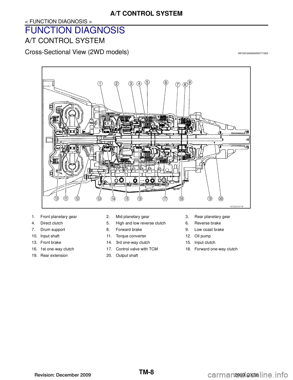
Cross-Sectional View (2WD models)INFOID:0000000003771805
1. Front planetary gear 2. Mid planetary gear 3. Rear planetary gear
4. Direct clutch 5. High and low reverse clutch 6. Reverse brake
7. Drum support 8. Forward brake 9. Low coast brake
10. Input shaft 11. Torque converter 12. Oil pump
13. Front brake 14. 3rd one-way clutch 15. Input clutch
16. 1st one-way clutch 17. Control valve with TCM 18. Forward one-way clutch
19. Rear extension 20. Output shaft
SCIA5267E
Revision: December 20092009 QX56
Page 3657 of 4171

A/T CONTROL SYSTEMTM-9
< FUNCTION DIAGNOSIS >
CEF
G H
I
J
K L
M A
B
TM
N
O P
Cross-Sectional View (4WD models)INFOID:0000000003771806
Shift MechanismINFOID:0000000003771807
The automatic transmission uses compact triple planet ary gear systems to improve power-transmission effi-
ciency, simplify construction and reduce weight.
It also employs an optimum shift control and super wide gear ratios. They improve starting performance and
acceleration during medium and high-speed operation.
CONSTRUCTION
1. Front planetary gear 2. Mid planetary gear 3. Rear planetary gear
4. Direct clutch 5. High and low reverse clutch 6. Reverse brake
7. Drum support 8. Forward brake 9. Low coast brake
10. Input shaft 11. Torque converter 12. Oil pump
13. Front brake 14. 3rd one-way clutch 15. Input clutch
16. 1st one-way clutch 17. Control valve with TCM 18. Forward one-way clutch
19. Adapter case 20. Output shaft
SCIA5268E
Revision: December 20092009 QX56
Page 3660 of 4171

TM-12
< FUNCTION DIAGNOSIS >
A/T CONTROL SYSTEM
Since both the forward brake and the reverse brake are released, torque from the input shaft drive is not trans-
mitted to the output shaft.
“P” Position
The same as for the “N” position, both the forward br ake and the reverse brake are released, so torque from
the input shaft drive is not transmitted to the output shaft.
The parking pawl linked with the select lever meshes with the parking gear and fastens the output shaft mechanically.
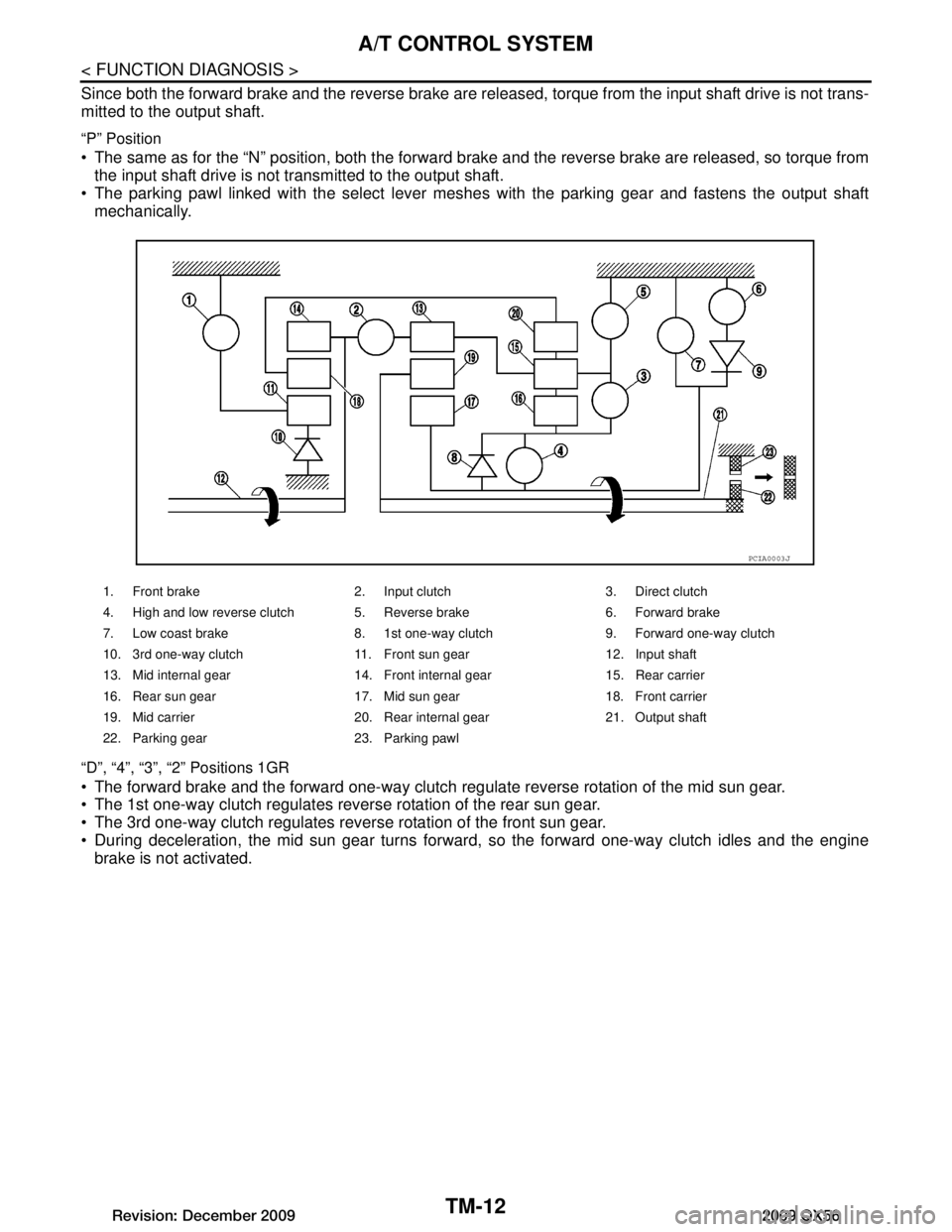
“D”, “4”, “3”, “2” Positions 1GR
The forward brake and the forward one-way clutch regulate reverse rotation of the mid sun gear.
The 1st one-way clutch regulates reverse rotation of the rear sun gear.
The 3rd one-way clutch regulates reverse rotation of the front sun gear.
During deceleration, the mid sun gear turns forward, so the forward one-way clutch idles and the engine
brake is not activated.
1. Front brake 2. Input clutch 3. Direct clutch
4. High and low reverse clutch 5. Reverse brake 6. Forward brake
7. Low coast brake 8. 1st one-way clutch 9. Forward one-way clutch
10. 3rd one-way clutch 11. Front sun gear 12. Input shaft
13. Mid internal gear 14. Front internal gear 15. Rear carrier
16. Rear sun gear 17. Mid sun gear 18. Front carrier
19. Mid carrier 20. Rear internal gear 21. Output shaft
22. Parking gear 23. Parking pawl
PCIA0003J
Revision: December 20092009 QX56
Page 3669 of 4171

A/T CONTROL SYSTEMTM-21
< FUNCTION DIAGNOSIS >
CEF
G H
I
J
K L
M A
B
TM
N
O P
CONTROL SYSTEM DIAGRAM
CAN CommunicationINFOID:0000000003771809
SYSTEM DESCRIPTION
CAN (Controller Area Network) is a serial communication li ne for real time application. It is an on-vehicle mul-
tiplex communication line with high data communication speed and excellent error detection ability. Many elec-
tronic control units are equipped onto a vehicle, and each control unit shares information and links with other
control units during operation (not independent). In CAN communication, control units are connected with 2
communication lines (CAN H line, CAN L line) allowing a high rate of information transmission with less wiring.
Each control unit transmits/receives data but selectively reads required data only. For details, refer to LAN-4,
"System Description".
SENSORS (or SIGNALS)
⇒TCM
⇒ACTUATORS
Transmission range switch
Accelerator pedal position sensor
Closed throttle position signal
Wide open throttle position signal
Engine speed signal
A/T fluid temperature sensor
Output speed sensor
Vehicle speed signal
Stop lamp switch signal
Input speed sensor
1st position switch signal
4th position switch signal
ATF pressure switch 2 signal
Tow mode switch signal Shift control
Line pressure control
Lock-up control
Engine brake control
Timing control
Fail-safe control
Self-diagnosis
CONSULT-III co
mmunication
line
Duet-EA control
CAN system Input clutch solenoid valve
Direct clutch solenoid valve
Front brake solenoid valve
High and low reverse clutch sole-
noid valve
Low coast brake solenoid valve
Torque converter clutch solenoid
valve
Line pressure solenoid valve
A/T CHECK indicator lamp
Starter relay
Back-up lamp relay
JSDIA1315GB
Revision: December 20092009 QX56
Page 3670 of 4171

TM-22
< FUNCTION DIAGNOSIS >
A/T CONTROL SYSTEM
Input/Output Signal of TCM
INFOID:0000000003771810
*1: Spare for output speed sensor.
*2: Spare for accelerator pedal position signal
*3: If these input and output signals are different, the TCM triggers the fail-safe function.
*4: CAN comm unications
*5: Used as a condition for starting self-diagnostics; if self-diagnostics are not started, it is judged that there is some kin d of error.
*6: A/T fluid temperature sensor 2 does not have any function.
Line Pressure ControlINFOID:0000000003771811
When an input torque signal equivalent to the engine drive force is sent from the ECM to the TCM, the TCM controls the line pressure solenoid.
Control item Line
pres- sure
control Vehicle
speed
control S h i f t
control Lock-up
control Engine
brake
control Fail-safe
function (*3) Self-diag-
nostics
function
Input Accelerator pedal position signal
(*4)XXXXX X X
Output speed sensor X X X X X X
Vehicle speed signal
(*1) (*4)XXXX X
Closed throttle position signal
(*4)(*2) X (*2) X X (*2) X (*5) X
Wide open throttle position signal
(*4)(*2) X (*2) X (*2) X (*5) X
Input speed sensor 1 X X X X X
Input speed sensor 2
(for 4th speed only) XX X X X
Engine speed signals
(*4)XX
Transmission range switch X X X X X X X
Stop lamp switch signal
(*4)XXX (*5) X
A/T fluid temperature sensors 1, 2 (*6) X X X X X X X
ASCD Operation signal
(*4)XXXX
Overdrive cancel sig-
nal
(*4)XXX
TCM power supply voltage signal X X X X X X
Output Direct clutch solenoid X X X X
Input clutch solenoid X X X X
High and low reverse clutch solenoid X X X X
Front brake solenoid X X X X
Low coast brake solenoid (ATF pressure
switch 2)
XX X X X
Line pressure solenoid X X X X X X X
TCC solenoid X X X
Starter relay XX
Revision: December 20092009 QX56
Page 3672 of 4171

TM-24
< FUNCTION DIAGNOSIS >
A/T CONTROL SYSTEM
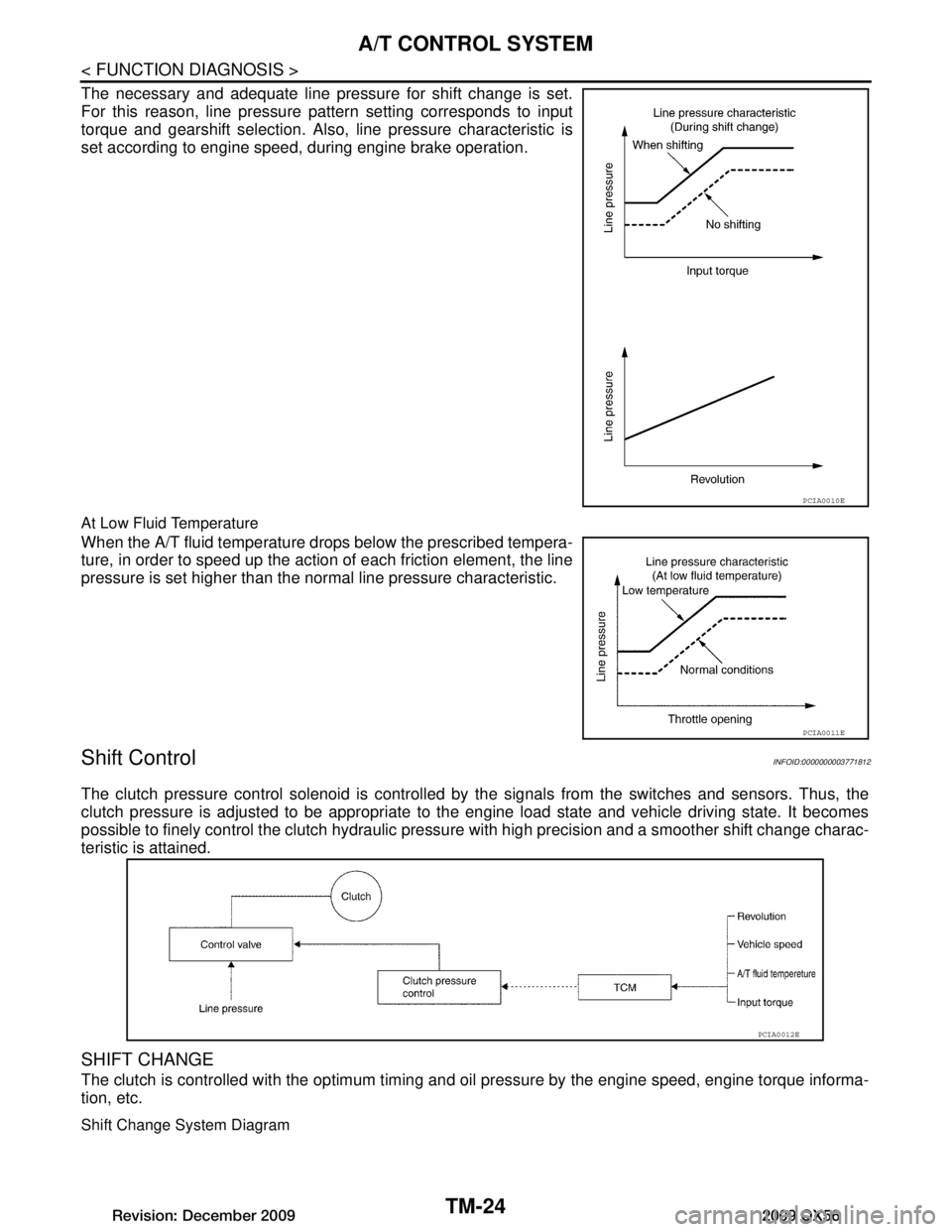
The necessary and adequate line pressure for shift change is set.
For this reason, line pressure pattern setting corresponds to input
torque and gearshift selection. Also, line pressure characteristic is
set according to engine speed, during engine brake operation.
At Low Fluid Temperature
When the A/T fluid temperature drops below the prescribed tempera-
ture, in order to speed up the action of each friction element, the line
pressure is set higher than the normal line pressure characteristic.
Shift ControlINFOID:0000000003771812
The clutch pressure control solenoid is controlled by the signals from the switches and sensors. Thus, the
clutch pressure is adjusted to be appropriate to the engine load state and vehicle driving state. It becomes
possible to finely control the clutch hydraulic pressu re with high precision and a smoother shift change charac-
teristic is attained.
SHIFT CHANGE
The clutch is controlled with the optimum timing and oil pressure by the engine speed, engine torque informa-
tion, etc.
Shift Change System Diagram
PCIA0010E
PCIA0011E
PCIA0012E
Revision: December 20092009 QX56