engine oil INFINITI QX56 2009 Factory Service Manual
[x] Cancel search | Manufacturer: INFINITI, Model Year: 2009, Model line: QX56, Model: INFINITI QX56 2009Pages: 4171, PDF Size: 84.65 MB
Page 3108 of 4171

BCM (BODY CONTROL MODULE)RF-17
< ECU DIAGNOSIS >
C
DE
F
G H
I
J
L
M A
B
RF
N
O P
HEADLAMP SW1 Headlamp switch OFF OFF
Headlamp switch 1st
ON
HEADLAMP SW2 Headlamp switch OFF
OFF
Headlamp switch 1st ON
HI BEAM SW High beam switch OFF
OFF
High beam switch HI ON
H/L WASH SW NOTE:
The item is indicated, but not monitored OFF
IGN ON SW Ignition switch OFF or ACC
OFF
Ignition switch ON ON
IGN SW CAN Ignition switch OFF or ACC
OFF
Ignition switch ON ON
INT VOLUME Wiper intermittent dial is in a dial position 1 - 7 1 - 7
I-KEY LOCK LOCK button of Intelligent Key is not pressed
OFF
LOCK button of Intelligent Key is pressed ON
I-KEY UNLOCK UNLOCK button of Intelligent Key is not pressed
OFF
UNLOCK button of Intelligent Key is pressed ON
KEY ON SW Mechanical key is removed from key cylinder
OFF
Mechanical key is inserted to key cylinder ON
OIL PRESS SW • Ignition switch OFF or ACC
• Engine running
OFF
Ignition switch ON ON
PASSING SW Other than lighting switch PASS
OFF
Lighting switch PASS ON
REAR DEF SW Rear window defogger switch OFF
OFF
Rear window defogger switch ON ON
RKE LOCK AND UN-
LOCK NOTE:
The item is indicated, but not monitored OFF
ON
RR WASHER SW Rear washer switch OFF
OFF
Rear washer switch ON ON
RR WIPER INT Rear wiper switch OFF
OFF
Rear wiper switch INT ON
RR WIPER ON Rear wiper switch OFF
OFF
Rear wiper switch ON ON
RR WIPER STOP Rear wiper stop position
OFF
Other than rear wiper stop position ON
TAIL LAMP SW Lighting switch OFF
OFF
Lighting switch 1ST ON
TRNK OPNR SW When back door opener switch is not pressed
OFF
When back door opener switch is pressed ON
TURN SIGNAL L Turn signal switch OFF
OFF
Turn signal switch LH ON
TURN SIGNAL R Turn signal switch OFF
OFF
Turn signal switch RH ON
VEHICLE SPEED While driving Equivalent to speedo meter reading
Monitor Item
Condition Value/Status
Revision: December 20092009 QX56
Page 3162 of 4171
RSU-14
< REMOVAL AND INSTALLATION >
REAR SUSPENSION MEMBER
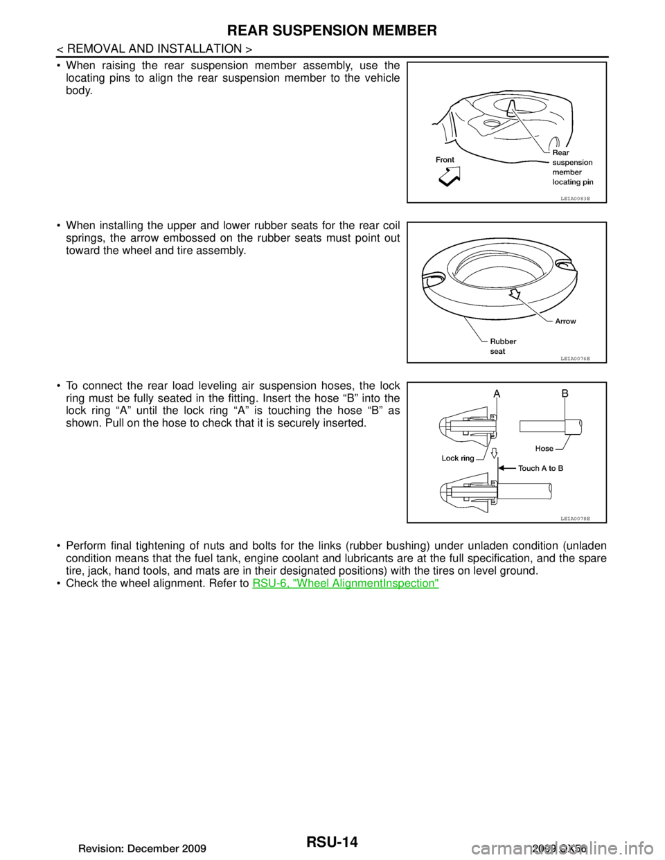
When raising the rear suspension member assembly, use thelocating pins to align the rear suspension member to the vehicle
body.
When installing the upper and lower rubber seats for the rear coil springs, the arrow embossed on the rubber seats must point out
toward the wheel and tire assembly.
To connect the rear load leveling air suspension hoses, the lock ring must be fully seated in the fitt ing. Insert the hose “B” into the
lock ring “A” until the lock ring “A” is touching the hose “B” as
shown. Pull on the hose to check that it is securely inserted.
Perform final tightening of nuts and bolts for the links (rubber bushing) under unladen condition (unladen condition means that the fuel tank, engine coolant and l ubricants are at the full specification, and the spare
tire, jack, hand tools, and mats are in their designated positions) with the tires on level ground.
Check the wheel alignment. Refer to RSU-6, "Wheel AlignmentInspection"
LEIA0083E
LEIA0076E
LEIA0078E
Revision: December 20092009 QX56
Page 3177 of 4171
SERVICE DATA AND SPECIFICATIONS (SDS)
RSU-29
< SERVICE DATA AND SPECIFICATIONS (SDS)
C
D F
G H
I
J
K L
M A
B
RSU
N
O P
SERVICE DATA AND SPECIFICATIONS (SDS)
SERVICE DATA AND SPECIFICATIONS (SDS)
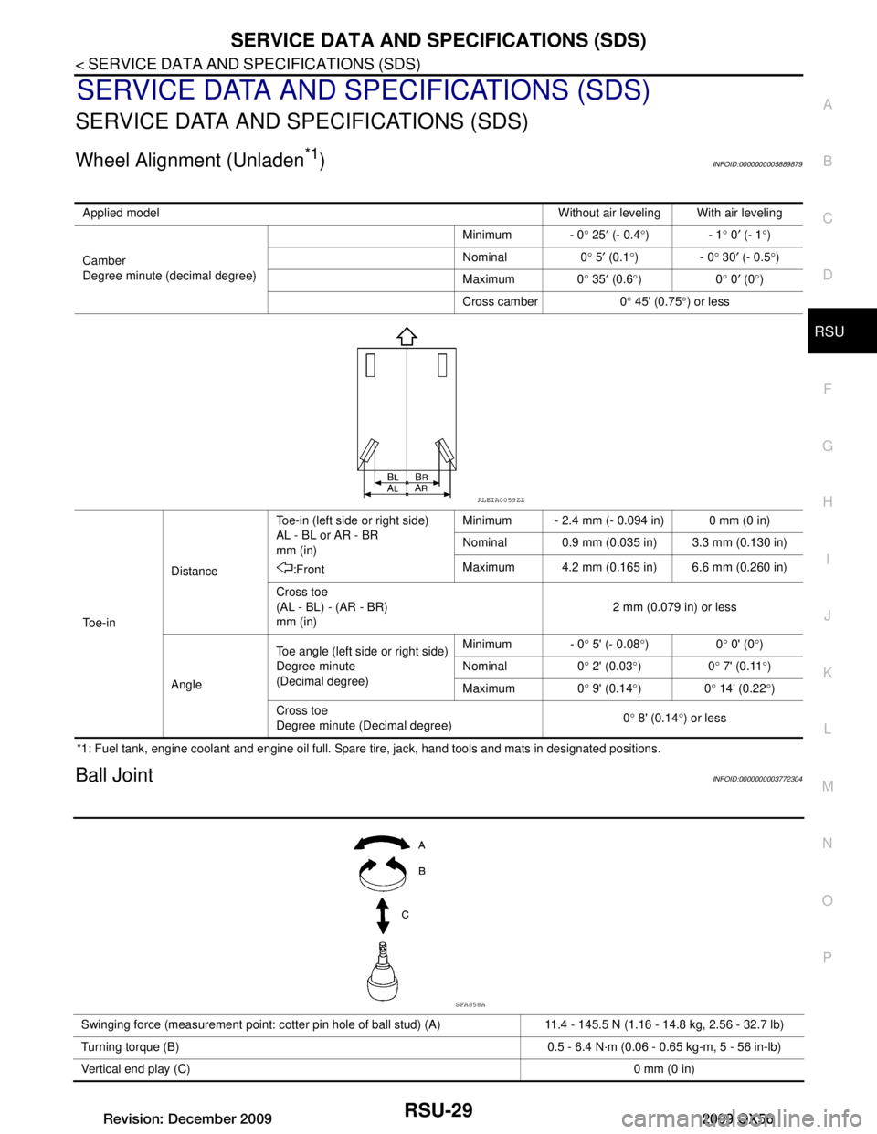
Wheel Alignment (Unladen*1)INFOID:0000000005889879
*1: Fuel tank, engine coolant and engine oil full. Spare tire, jack, hand tools and mats in designated positions.
Ball JointINFOID:0000000003772304
Applied model Without air leveling With air leveling
Camber
Degree minute (decimal degree) Minimum - 0
° 25 ′ (- 0.4 °)- 1 ° 0 ′ (- 1 °)
Nominal 0 ° 5 ′ (0.1 °)- 0 ° 30 ′ (- 0.5 °)
Maximum 0 ° 35 ′ (0.6 °)0 ° 0 ′ (0 °)
Cross camber 0 ° 45' (0.75 °) or less
To e - i n Distance
Toe-in (left side or right side)
AL - BL or AR - BR
mm (in)
:Front Minimum - 2.4 mm (- 0.094 in) 0 mm (0 in)
Nominal 0.9 mm (0.035 in) 3.3 mm (0.130 in)
Maximum 4.2 mm (0.165 in) 6.6 mm (0.260 in)
Cross toe
(AL - BL) - (AR - BR)
mm (in) 2 mm (0.079 in) or less
Angle Toe angle (left side or right side)
Degree minute
(Decimal degree) Minimum - 0
° 5' (- 0.08 °)0 ° 0' (0 °)
Nominal 0 ° 2' (0.03 °)0 ° 7' (0.11 °)
Maximum 0 ° 9' (0.14 °)0 ° 14' (0.22 °)
Cross toe
Degree minute (Decimal degree) 0
° 8' (0.14 °) or less
ALEIA0059ZZ
Swinging force (measurement point: cotter pin hole of ball stud) (A) 11.4 - 145.5 N (1.16 - 14.8 kg, 2.56 - 32.7 lb)
Turning torque (B) 0.5 - 6.4 N·m (0.06 - 0.65 kg-m, 5 - 56 in-lb)
Vertical end play (C) 0 mm (0 in)
SFA858A
Revision: December 20092009 QX56
Page 3178 of 4171
RSU-30
< SERVICE DATA AND SPECIFICATIONS (SDS)
SERVICE DATA AND SPECIFICATIONS (SDS)
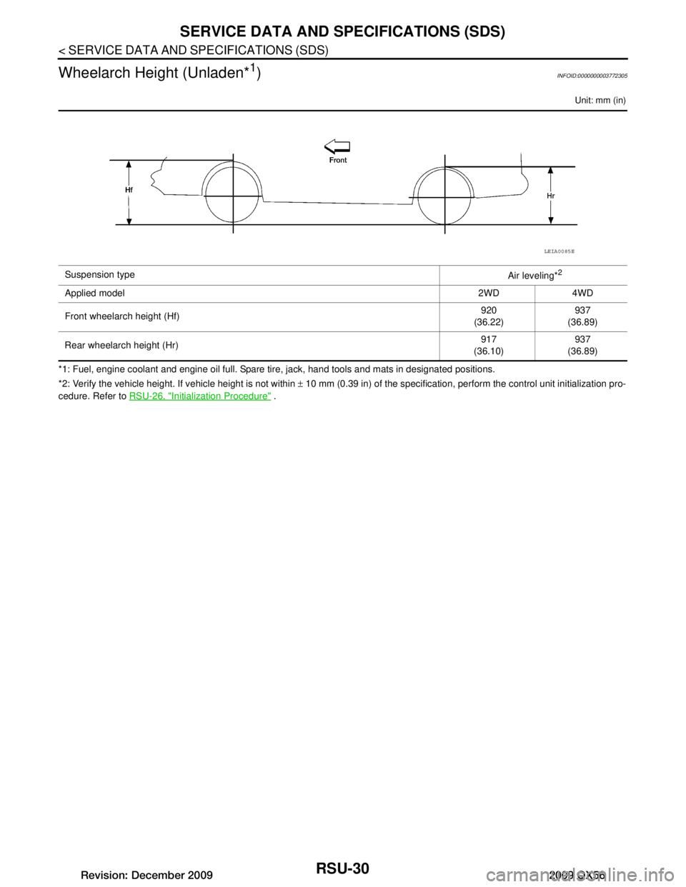
Wheelarch Height (Unladen*
1)INFOID:0000000003772305
Unit: mm (in)
*1: Fuel, engine coolant and engine oil full. Spare tire, jack, hand tools and mats in designated positions.
*2: Verify the vehicle height. If vehicle height is not within ± 10 mm (0.39 in) of the specification, perform the control unit initialization pro-
cedure. Refer to RSU-26, "Initialization Procedure"
.
Suspension type
Air leveling*
2
Applied model2WD 4WD
Front wheelarch height (Hf) 920
(36.22) 937
(36.89)
Rear wheelarch height (Hr) 917
(36.10) 937
(36.89)
LEIA0085E
Revision: December 20092009 QX56
Page 3232 of 4171
PRECAUTIONSSCS-39
< PRECAUTION >
C
DF
G H
I
J
K L
M A
B
SCS
N
O P
PRECAUTION
PRECAUTIONS
Precaution for Supplemental Restraint System (SRS) "AIR BAG" and "SEAT BELT
PRE-TENSIONER"
INFOID:0000000005867805
The Supplemental Restraint System such as “AIR BAG” and “SEAT BELT PRE-TENSIONER”, used along
with a front seat belt, helps to reduce the risk or severi ty of injury to the driver and front passenger for certain
types of collision. This system includes seat belt switch inputs and dual stage front air bag modules. The SRS
system uses the seat belt switches to determine the front air bag deployment, and may only deploy one front
air bag, depending on the severity of a collision and w hether the front occupants are belted or unbelted.
Information necessary to service the system safely is included in the SR and SB section of this Service Man-
ual.
WARNING:
• To avoid rendering the SRS inoper ative, which could increase the risk of personal injury or death in
the event of a collision which would result in air bag inflation, all maintenance must be performed by
an authorized NISSAN/INFINITI dealer.
• Improper maintenance, including in correct removal and installation of the SRS, can lead to personal
injury caused by unintentional act ivation of the system. For removal of Spiral Cable and Air Bag
Module, see the SR section.
• Do not use electrical test equipm ent on any circuit related to the SRS unless instructed to in this
Service Manual. SRS wiring harnesses can be identi fied by yellow and/or orange harnesses or har-
ness connectors.
PRECAUTIONS WHEN USING POWER TOOLS (AIR OR ELECTRIC) AND HAMMERS
WARNING:
• When working near the Airbag Diagnosis Sensor Un it or other Airbag System sensors with the Igni-
tion ON or engine running, DO NOT use air or el ectric power tools or strike near the sensor(s) with a
hammer. Heavy vibration could activate the sensor( s) and deploy the air bag(s), possibly causing
serious injury.
• When using air or electric power tools or hammers, always switch the Ignition OFF, disconnect the battery, and wait at least 3 minutes before performing any service.
Precaution for Rear SuspensionINFOID:0000000003772362
• When installing the rubber bushings, the final tightening must be done under unladen condition and with thetires on level ground. Oil will shorten the life of the rubber bushings, so wipe off any spilled oil immediately.
• Unladen condition means the fuel tank, engine coolant and lubricants are at the full specification. The spare tire, jack, hand tools, and mats are in their designated positions.
• After installing suspension components, check the wheel alignment.
• Caulking nuts are not reusable. Always use new caulking nuts for installation. New caulking nuts are pre-
oiled, do not apply any additional lubrication.
Revision: December 20092009 QX56
Page 3360 of 4171
![INFINITI QX56 2009 Factory Service Manual SEC-50
< ECU DIAGNOSIS >[WITH INTELLIGENT KEY SYSTEM]
BCM (BODY CONTROL MODULE)
HEADLAMP SW1Headlamp switch OFF OFF
Headlamp switch 1st
ON
HEADLAMP SW2 Headlamp switch OFF
OFF
Headlamp switch 1st ON
H INFINITI QX56 2009 Factory Service Manual SEC-50
< ECU DIAGNOSIS >[WITH INTELLIGENT KEY SYSTEM]
BCM (BODY CONTROL MODULE)
HEADLAMP SW1Headlamp switch OFF OFF
Headlamp switch 1st
ON
HEADLAMP SW2 Headlamp switch OFF
OFF
Headlamp switch 1st ON
H](/img/42/57031/w960_57031-3359.png)
SEC-50
< ECU DIAGNOSIS >[WITH INTELLIGENT KEY SYSTEM]
BCM (BODY CONTROL MODULE)
HEADLAMP SW1Headlamp switch OFF OFF
Headlamp switch 1st
ON
HEADLAMP SW2 Headlamp switch OFF
OFF
Headlamp switch 1st ON
HI BEAM SW High beam switch OFF
OFF
High beam switch HI ON
H/L WASH SW NOTE:
The item is indicated, but not monitored OFF
IGN ON SW Ignition switch OFF or ACC
OFF
Ignition switch ON ON
IGN SW CAN Ignition switch OFF or ACC
OFF
Ignition switch ON ON
INT VOLUME Wiper intermittent dial is in a dial position 1 - 7 1 - 7
I-KEY LOCK LOCK button of Intelligent Key is not pressed
OFF
LOCK button of Intelligent Key is pressed ON
I-KEY UNLOCK UNLOCK button of Intelligent Key is not pressed
OFF
UNLOCK button of Intelligent Key is pressed ON
KEY ON SW Mechanical key is removed from key cylinder
OFF
Mechanical key is inserted to key cylinder ON
OIL PRESS SW • Ignition switch OFF or ACC
• Engine running
OFF
Ignition switch ON ON
PASSING SW Other than lighting switch PASS
OFF
Lighting switch PASS ON
REAR DEF SW Rear window defogger switch OFF
OFF
Rear window defogger switch ON ON
RKE LOCK AND UN-
LOCK NOTE:
The item is indicated, but not monitored OFF
ON
RR WASHER SW Rear washer switch OFF
OFF
Rear washer switch ON ON
RR WIPER INT Rear wiper switch OFF
OFF
Rear wiper switch INT ON
RR WIPER ON Rear wiper switch OFF
OFF
Rear wiper switch ON ON
RR WIPER STOP Rear wiper stop position
OFF
Other than rear wiper stop position ON
TAIL LAMP SW Lighting switch OFF
OFF
Lighting switch 1ST ON
TRNK OPNR SW When back door opener switch is not pressed
OFF
When back door opener switch is pressed ON
TURN SIGNAL L Turn signal switch OFF
OFF
Turn signal switch LH ON
TURN SIGNAL R Turn signal switch OFF
OFF
Turn signal switch RH ON
VEHICLE SPEED While driving Equivalent to speedometer reading
Monitor Item
Condition Value/Status
Revision: December 20092009 QX56
Page 3406 of 4171
![INFINITI QX56 2009 Factory Service Manual SEC-96
< ECU DIAGNOSIS >[WITH INTELLIGENT KEY SYSTEM]
IPDM E/R (INTELLIGENT POWER DI
STRIBUTION MODULE ENGINE ROOM)
IPDM E/R (INTELLIGENT POWER DISTRIBUTION MODULE ENGINE
ROOM)
Reference ValueINFOID: INFINITI QX56 2009 Factory Service Manual SEC-96
< ECU DIAGNOSIS >[WITH INTELLIGENT KEY SYSTEM]
IPDM E/R (INTELLIGENT POWER DI
STRIBUTION MODULE ENGINE ROOM)
IPDM E/R (INTELLIGENT POWER DISTRIBUTION MODULE ENGINE
ROOM)
Reference ValueINFOID:](/img/42/57031/w960_57031-3405.png)
SEC-96
< ECU DIAGNOSIS >[WITH INTELLIGENT KEY SYSTEM]
IPDM E/R (INTELLIGENT POWER DI
STRIBUTION MODULE ENGINE ROOM)
IPDM E/R (INTELLIGENT POWER DISTRIBUTION MODULE ENGINE
ROOM)
Reference ValueINFOID:0000000004221479
VALUES ON THE DIAGNOSIS TOOL
Monitor Item ConditionValue/Status
MOTOR FAN REQ Engine idle speed Changes depending on engine
coolant temperature, air conditioner
operation status, vehicle speed,
etc.0 - 100 %
A/C COMP REQ A/C switch OFF
OFF
A/C switch ON ON
TAIL&CLR REQ Lighting switch OFF
OFF
Lighting switch 1ST, 2ND, HI or AUTO (Light is illuminated) ON
HL LO REQ Lighting switch OFF
OFF
Lighting switch 2ND HI or AUTO (Light is illuminated) ON
HL HI REQ Lighting switch OFF
OFF
Lighting switch HI ON
FR FOG REQ Lighting switch 2ND or AUTO (Light
is illuminated) Front fog lamp switch OFF OFF
• Front fog lamp switch ON
• Daytime light activated (Canada
only) ON
HL WASHER REQ NOTE:
This item is displayed, but cannot be monitored.
OFF
FR WIP REQ Ignition switch ON Front wiper switch OFF
STOP
Front wiper switch INT 1LOW
Front wiper switch LO LOW
Front wiper switch HI HI
WIP AUTO STOP Ignition switch ON Front wiper stop position
STOP P
Any position other than front wiper
stop position ACT P
WIP PROT Ignition switch ON Front wiper operates normally OFF
Front wiper stops at fail-safe opera-
tion
BLOCK
ST RLY REQ Ignition switch OFF or ACC
OFF
Ignition switch START ON
IGN RLY Ignition switch OFF or ACC
OFF
Ignition switch ON ON
RR DEF REQ Rear defogger switch OFF
OFF
Rear defogger switch ON ON
OIL P SW Ignition switch OFF, ACC or engine running
OPEN
Ignition switch ON CLOSE
DTRL REQ Daytime light system requested OFF with CONSULT-III.
OFF
Daytime light system requested ON with CONSULT-III. ON
HOOD SW Hood closed.
OFF
Hood open. ON
Revision: December 20092009 QX56
Page 3411 of 4171
![INFINITI QX56 2009 Factory Service Manual IPDM E/R (INTELLIGENT POWER DISTRIBUTION MODULE ENGINE ROOM)
SEC-101
< ECU DIAGNOSIS > [WITH INTELLIGENT KEY SYSTEM]
C
D
E
F
G H
I
J
L
M A
B
SEC
N
O P
41 Y/B Hood switch Input —Hood closed OFF
0V
Ho INFINITI QX56 2009 Factory Service Manual IPDM E/R (INTELLIGENT POWER DISTRIBUTION MODULE ENGINE ROOM)
SEC-101
< ECU DIAGNOSIS > [WITH INTELLIGENT KEY SYSTEM]
C
D
E
F
G H
I
J
L
M A
B
SEC
N
O P
41 Y/B Hood switch Input —Hood closed OFF
0V
Ho](/img/42/57031/w960_57031-3410.png)
IPDM E/R (INTELLIGENT POWER DISTRIBUTION MODULE ENGINE ROOM)
SEC-101
< ECU DIAGNOSIS > [WITH INTELLIGENT KEY SYSTEM]
C
D
E
F
G H
I
J
L
M A
B
SEC
N
O P
41 Y/B Hood switch Input —Hood closed OFF
0V
Hood open ON Battery voltage
42 GR Oil pressure switch Input — Engine running
Battery voltage
Engine stopped 0V
43 L/Y Wiper auto stop signal Input ON or
START Wiper switch OFF, LO, INT Battery voltage
44 BR Daytime light relay
control Input ONDaytime light system active
0V
Daytime light system inactive Battery voltage
45 G/W Horn relay control Input ON When door locks are operated
using keyfob or Intelligent Key
(OFF
→ ON)* Battery voltage
→ 0V
46 GR Fuel pump relay con-
trol
Input —Ignition switch ON or START
0V
Ignition switch OFF or ACC Battery voltage
47 O Throttle control motor
relay control
Input —Ignition switch ON or START
0V
Ignition switch OFF or ACC Battery voltage
48 B/R Starter relay (inhibit
switch) InputON or
START Selector lever in "P" or "N"
0V
Selector lever any other posi-
tion Battery voltage
49 R/L Trailer tow relay Output ON Lighting
switch must
be in the 1st
positionOFF
0V
ON Battery voltage
50 W/R Front fog lamp (LH) Output ON or
START Lighting
switch must
be in the 2nd
position
(LOW beam
is ON) and
the front fog
lamp switch OFF
0V
ON Battery voltage
51 W/R Front fog lamp (RH) Output ON or
START Lighting
switch must
be in the 2nd
position
(LOW beam
is ON) and
the front fog
lamp switch OFF
0V
ON Battery voltage
52 L LH low beam head-
lamp Output — Lighting switch in 2nd position Battery voltage
54 R/Y RH low beam head-
lamp Output — Lighting switch in 2nd position Battery voltage
55 G LH high beam head-
lamp Output —Lighting switch in 2nd position
and placed in HIGH or PASS
position Battery voltage
56 L/W RH high beam head-
lamp Output —Lighting switch in 2nd position
and placed in HIGH or PASS
position Battery voltage
57 R/L Parking, license, and
tail lamp
Output ONLighting
swi
t
ch 1st po-
sition OFF
0V
ON Battery voltage
Te r m i n a l
Wire
color Signal name Signal
input/
output Measuring condition
Reference value(Approx.)
Igni-
tion
switch Operation or condition
Revision: December 20092009 QX56
Page 3412 of 4171
![INFINITI QX56 2009 Factory Service Manual SEC-102
< ECU DIAGNOSIS >[WITH INTELLIGENT KEY SYSTEM]
IPDM E/R (INTELLIGENT POWER DI
STRIBUTION MODULE ENGINE ROOM)
*: When horn reminder is ON
Fail SafeINFOID:0000000004221483
CAN COMMUNICATION CONT INFINITI QX56 2009 Factory Service Manual SEC-102
< ECU DIAGNOSIS >[WITH INTELLIGENT KEY SYSTEM]
IPDM E/R (INTELLIGENT POWER DI
STRIBUTION MODULE ENGINE ROOM)
*: When horn reminder is ON
Fail SafeINFOID:0000000004221483
CAN COMMUNICATION CONT](/img/42/57031/w960_57031-3411.png)
SEC-102
< ECU DIAGNOSIS >[WITH INTELLIGENT KEY SYSTEM]
IPDM E/R (INTELLIGENT POWER DI
STRIBUTION MODULE ENGINE ROOM)
*: When horn reminder is ON
Fail SafeINFOID:0000000004221483
CAN COMMUNICATION CONTROL
When CAN communication with ECM and BCM is impossible, IPDM E/R performs fail-safe control. After CAN
communication recovers normally, it also returns to normal control.
If No CAN Communication Is Available With ECM
If No CAN Communication Is Available With BCM
IGNITION RELAY MALFUNCTION DETECTION FUNCTION
• IPDM E/R monitors the voltage at the contact circuit and excitation coil circuit of the ignition relay inside it.
• IPDM E/R judges the ignition relay error if the voltage differs between the contact circuit and the excitation
coil circuit.
• If the ignition relay cannot turn OFF due to contact seizure, it activates the tail lamp relay for 10 minutes to alert the user to the ignition relay malfunction when the ignition switch is turned OFF.
NOTE:
The tail lamp turns OFF when the ignition switch is turned ON.
FRONT WIPER CONTROL
IPDM E/R detects front wiper stop posit ion by a front wiper auto stop signal.
59 B Ground Input ——0V
60 B/W Rear window defog-
ger relay
OutputON or
START Rear defogger switch ON
Battery voltage
Rear defogger switch OFF 0V
61 BR Fuse 32 Output OFF—Battery voltage
Te r m i n a l
Wire
color Signal name Signal
input/
output Measuring condition
Reference value(Approx.)
Igni-
tion
switch Operation or condition
Control part
Fail-safe in operation
Cooling fan • Turns ON the cooling fan relay when the ignition switch is turned ON
• Turns OFF the cooling fan relay when the ignition switch is turned OFF
Control part
Fail-safe in operation
Headlamp • Turns ON the headlamp low relay when the ignition switch is turned ON
• Turns OFF the headlamp low relay when the ignition switch is turned OFF
• Headlamp high relay OFF
•Parking lamps
• License plate lamps
• Tail lamps • Turns ON the tail lamp relay when the ignition switch is turned ON
• Turns OFF the tail lamp relay when the ignition switch is turned OFF
Front wiper • The status just before activation of fail-safe control is maintained until the ignition
switch is turned OFF while the front wiper is operating at LO or HI speed.
• The wiper is operated at LO speed until the ignition switch is turned OFF if the fail- safe control is activated while the front wipe r is set in the INT mode and the front wiper
motor is operating.
Rear window defogger Rear window defogger relay OFF
A/C compressor A/C relay OFF
Front fog lamps Front fog lamp relay OFF
Ignition switch Ignition relayTail lamp relay
ON ON —
OFF OFF —
Revision: December 20092009 QX56
Page 3604 of 4171
POWER STEERING FLUIDST-13
< ON-VEHICLE MAINTENANCE >
C
DE
F
H I
J
K L
M A
B
ST
N
O P
ON-VEHICLE MAINTENANCE
POWER STEERING FLUID
Checking Fluid LevelINFOID:0000000004187604
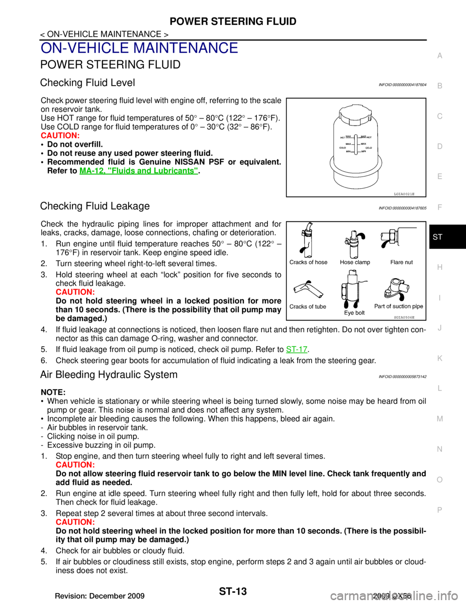
Check power steering fluid level with engine off, referring to the scale
on reservoir tank.
Use HOT range for fluid temperatures of 50 ° – 80 °C (122 ° – 176 °F).
Use COLD range for fluid temperatures of 0 ° – 30 °C (32 ° – 86 °F).
CAUTION:
Do not overfill.
Do not reuse any used power steering fluid.
Recommended fluid is Genuine NISSAN PSF or equivalent. Refer to MA-12, "Fluids and Lubricants"
.
Checking Fluid LeakageINFOID:0000000004187605
Check the hydraulic piping lines for improper attachment and for
leaks, cracks, damage, loose connections, chafing or deterioration.
1. Run engine until fluid temperature reaches 50 ° – 80 °C (122 ° –
176 °F) in reservoir tank. Keep engine speed idle.
2. Turn steering wheel right-to-left several times.
3. Hold steering wheel at each “lock” position for five seconds to check fluid leakage.
CAUTION:
Do not hold steering wheel in a locked position for more
than 10 seconds. (There is the possibility that oil pump may
be damaged.)
4. If fluid leakage at connections is noticed, then loos en flare nut and then retighten. Do not over tighten con-
nector as this can damage O-ring, washer and connector.
5. If fluid leakage from oil pump is noticed, check oil pump. Refer to ST-17
.
6. Check steering gear boots for accumulation of fluid indicating a leak from the steering gear.
Air Bleeding Hydraulic SystemINFOID:0000000005873142
NOTE:
When vehicle is stationary or while steering wheel is being turned slowly, some noise may be heard from oil pump or gear. This noise is normal and does not affect any system.
Incomplete air bleeding causes the fo llowing. When this happens, bleed air again.
- Air bubbles in reservoir tank.
- Clicking noise in oil pump.
- Excessive buzzing in oil pump.
1. Stop engine, and then turn steering wheel fully to right and left several times. CAUTION:
Do not allow steering fluid reservoir tank to go below the MIN level line. Check tank frequently and
add fluid as needed.
2. Run engine at idle speed. Turn steering wheel fully right and then fully left, hold for about three seconds.
Then check for fluid leakage.
3. Repeat step 2 several times at about three second intervals. CAUTION:
Do not hold steeri ng wheel in the locked position for more than 10 seconds. (There is the possibil-
ity that oil pump may be damaged.)
4. Check for air bubbles or cloudy fluid.
5. If air bubbles or cloudiness still exists, stop engine, perform steps 2 and 3 again until air bubbles or cloud-
iness does not exist.
LGIA0021E
SGIA0506E
Revision: December 20092009 QX56