check oil INFINITI QX56 2009 Factory User Guide
[x] Cancel search | Manufacturer: INFINITI, Model Year: 2009, Model line: QX56, Model: INFINITI QX56 2009Pages: 4171, PDF Size: 84.65 MB
Page 656 of 4171

CCS
INSPECTION AND ADJUSTMENTCCS-5
< BASIC INSPECTION >
C
DE
F
G H
I
J
K L
M B
N P A
INSPECTION AND ADJUSTMENT
ADDITIONAL SERVICE WHEN REPLACING CONTROL UNIT
ADDITIONAL SERVICE WHEN REPL ACING CONTROL UNIT : Description
INFOID:0000000003776923
Always perform the laser beam aiming adjustment after repl acing the ICC unit. In addition, test the ICC sys-
tem operations to see if it functions normally.
ADDITIONAL SERVICE WHEN REPLACING CONTROL UNIT : Special Repair Re-
quirement
INFOID:0000000003776924
1.LASER BEAM AIMING ADJUSTMENT
Adjust laser beam aiming. Refer to CCS-5, "
LASER BEAM AIMING ADJUSTMENT : Outline of Laser Beam
Aiming Adjustment Procedure".
>> GO TO 2
2.ICC SYSTEM ACTION TEST
1. Perform the ICC system operation test. Refer to CCS-8, "
ACTION TEST : ICC System Running Test".
2. Check that the ICC system operates normally.
>> INSPECTION END.
LASER BEAM AIMI NG ADJUSTMENT
LASER BEAM AIMING ADJUSTMENT : Outlin e of Laser Beam Aiming Adjustment
Procedure
INFOID:0000000003776925
CAUTION:
• The laser beam aiming adjustment can not be performed without CONSULT-III.
• The laser beam aiming adjustment must be performed every time the ICC sensor is removed,
installed or has been moved as a result of a collision.
1. Prepare the vehicle and the work area.
2. Set up the ICC target board. For details, refer to Technical Service Bulletin.
3. Adjust the sensor following the procedure on CONSULT-III.
4. Check system operation after the adjustment.
LASER BEAM AIMING ADJU STMENT : PreparationINFOID:0000000003776926
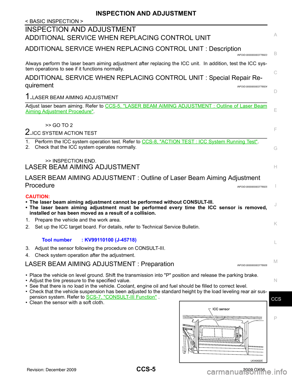
• Place the vehicle on level ground. Shift the transmi ssion into "P" position and release the parking brake.
• Adjust the tire pressure to the specified value.
• See that there is no load in the vehicle. Coolant , engine oil and fuel should be filled to correct level.
• Check that the vehicle suspension has been adjusted to the standard height by the load leveling rear air sus-
pension system. Refer to SCS-7, "
CONSULT-III Function" .
• Clean the sensor with a soft cloth. Tool number : KV99110100 (J-45718)
LKIA0632E
Revision: December 20092009 QX56
Page 685 of 4171

CCS-34
< COMPONENT DIAGNOSIS >
DTC 90 STOP LAMP RLY FIX
1. Disconnect ICC brake hold relay.
2. Check continuity between ICC brake hold relay E134 terminal 7and terminal 6.
Are continuity test results as specified?
YES >> Replace ICC unit. Refer to CCS-70, "ICC Unit". Erase
DTC and perform ICC system running test. Refer to
CCS-8, "
ACTION TEST : ICC System Running Test".
NO >> Replace ICC brake hold relay. Erase DTC and perform ICC system running test. Refer to CCS-8, "
ACTION
TEST : ICC System Running Test".
11 . CHECK HARNESS THROUGH ICC UNIT, ICC BRAKE HOLD RELAY, AND GROUND
1. Disconnect ICC unit and ICC brake hold relay harness connec- tors.
2. Check continuity between I CC unit harness connector B17 ter-
minal 47 and ICC brake hold relay harness connector E134 ter-
minal 1.
3. Check continuity between I CC unit harness connector B17 ter-
minal 47 and ground.
4. Check continuity between ICC brake hold relay harness connec- tor E134 terminal 2 and ground.
Are continuity test results as specified?
YES >> GO TO 12
NO >> • Repair harness through ICC unit and ICC brake hold relay, or between ICC brake hold relay and ground.
• Erase DTC and perform ICC system running test.
Refer to CCS-8, "
ACTION TEST : ICC System Run-
ning Test".
12.CHECK ICC BRAKE HOLD RELAY
Check continuity between ICC brake hold relay terminal 1 and termi-
nal 2.
Does continuity exist?
YES >> GO TO 13
NO >> Replace ICC brake hold relay. Erase DTC and perform ICC system running test. Refer to CCS-8, "
ACTION
TEST : ICC System Running Test".
13.CHECK ICC UNIT STANDARD VOLTAGE Continuity should not exist.
SKIA6659E
47 - 1
Continuity should exist.
47 - Ground Continuity should not exist.
SKIA6660E
Continuity should exist.
SKIA6661E
Continuity should exist
(minimal resistance through coil will exist)
SKIA6662E
Revision: December 20092009 QX56
Page 747 of 4171

PRECAUTIONSCO-3
< PRECAUTION >
C
DE
F
G H
I
J
K L
M A
CO
NP
O
5. When the repair work is completed, return the ignition switch to the
″LOCK ″ position before connecting
the battery cables. (At this time, the steering lock mechanism will engage.)
6. Perform a self-diagnosis check of al l control units using CONSULT-III.
Precaution for Liquid GasketINFOID:0000000003771278
REMOVAL OF LIQUID GASKET SEALING
• After removing the bolts and nuts, separate the mating surface and
remove the old liquid gasket sealing using Tool.
CAUTION:
Do not damage the mating surfaces.
• Tap the seal cutter to insert it (1).
• In areas where the Tool is difficult to use, lightly tap to slide it (2).
LIQUID GASKET APPLICATION PROCEDURE
1. Remove the old liquid gasket adhering to the gasket application surface and the mating surface using suitable tool.
• Remove the liquid gasket completely from the groove of the
liquid gasket application surface, bolts, and bolt holes.
2. Thoroughly clean the mating surfaces and remove adhering moisture, grease and foreign material.
3. Attach the liquid gasket tube to the Tool. Use Genuine RTV Silicone Sealant or equivalent. Refer to
GI-15, "
Recommended Chemical Products and Sealants".
4. Apply the liquid gasket without breaks to the specified location with the specified dimensions.
• If there is a groove for the liquid gasket application, apply theliquid gasket to the groove.
• As for the bolt holes, normally apply the liquid gasket inside
the holes. If specified in the procedure, it should also be
applied outside the holes.
• Within five minutes of liquid gasket application, install the mat-
ing component.
• If the liquid gasket protrudes, wipe it off immediately.
• Do not retighten after the installation.
• Wait 30 minutes or more after installation before refilling the engine with engine oil and engine coolant.
CAUTION:
If there are specific instructions in this manual, observe them.
Tool number : KV10111100 (J-37228)
WBIA0566E
PBIC0003E
Tool number : WS39930000 ( — )
WBIA0567E
SEM159F
Revision: December 20092009 QX56
Page 748 of 4171

CO-4
< PREPARATION >
PREPARATION
PREPARATION
PREPARATION
Special Service ToolINFOID:0000000003771279
The actual shapes of Kent-Moore tools may differ from those of special service tools illustrated here.
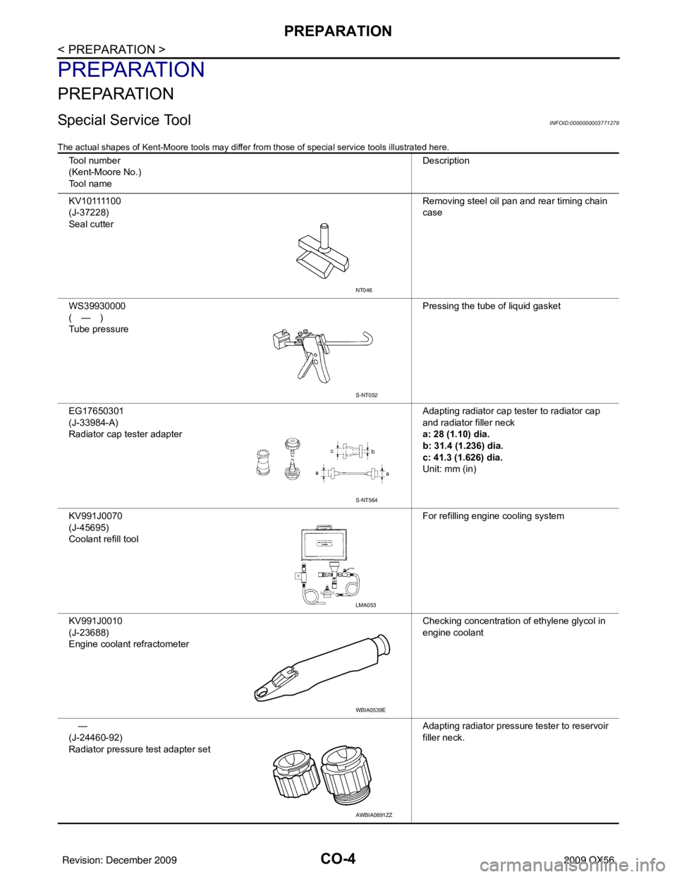
Tool number
(Kent-Moore No.)
Tool name Description
K V 1 0 1111 0 0
(J-37228)
Seal cutter Removing steel oil pan and rear timing chain
case
WS39930000
(—)
Tube pressure Pressing the tube of liquid gasket
EG17650301
(J-33984-A)
Radiator cap tester adapter Adapting radiator cap tester to radiator cap
and radiator filler neck
a: 28 (1.10) dia.
b: 31.4 (1.236) dia.
c: 41.3 (1.626) dia.
Unit: mm (in)
KV991J0070
(J-45695)
Coolant refill tool For refilling engine cooling system
KV991J0010
(J-23688)
Engine coolant refractometer Checking concentration of ethylene glycol in
engine coolant
—
(J-24460-92)
Radiator pressure test adapter set Adapting radiator pressure tester to reservoir
filler neck.
NT046
S-NT052
S-NT564
LMA053
WBIA0539E
AWBIA0891ZZ
Revision: December 20092009 QX56
Page 756 of 4171

CO-12
< ON-VEHICLE MAINTENANCE >
ENGINE COOLANT
5. Remove the reservoir tank to drain the engine coolant, then clean the reservoir tank before installing it.
6. Check the drained coolant for contaminants such as rust, corrosion or discoloration.
If the coolant is contaminated, flus h the engine cooling system. Refer to CO-11, "
Changing Engine Cool-
ant".
REFILLING ENGINE COOLANT
1. Close the radiator drain plug. Install the reservoir t ank, cylinder block drain plug, and the oil cooler hose, if
removed for a total system drain or for engine removal or repair.
• The radiator must be completely empty of coolant and water.
• Apply sealant to the threads of the cylinder bl ock drain plug. Use Genuine High Performance Thread
Sealant or equivalent. Refer to GI-15, "
Recommended Chemical Products and Sealants".
2. Set the vehicle heater controls to the full HOT and heat er ON position. Turn the vehicle ignition ON with
the engine OFF as necessary to activate the heater mode.
3. Remove the vented reservoir cap and replace it with a non-vented reservoir cap before filling the cooling
system.
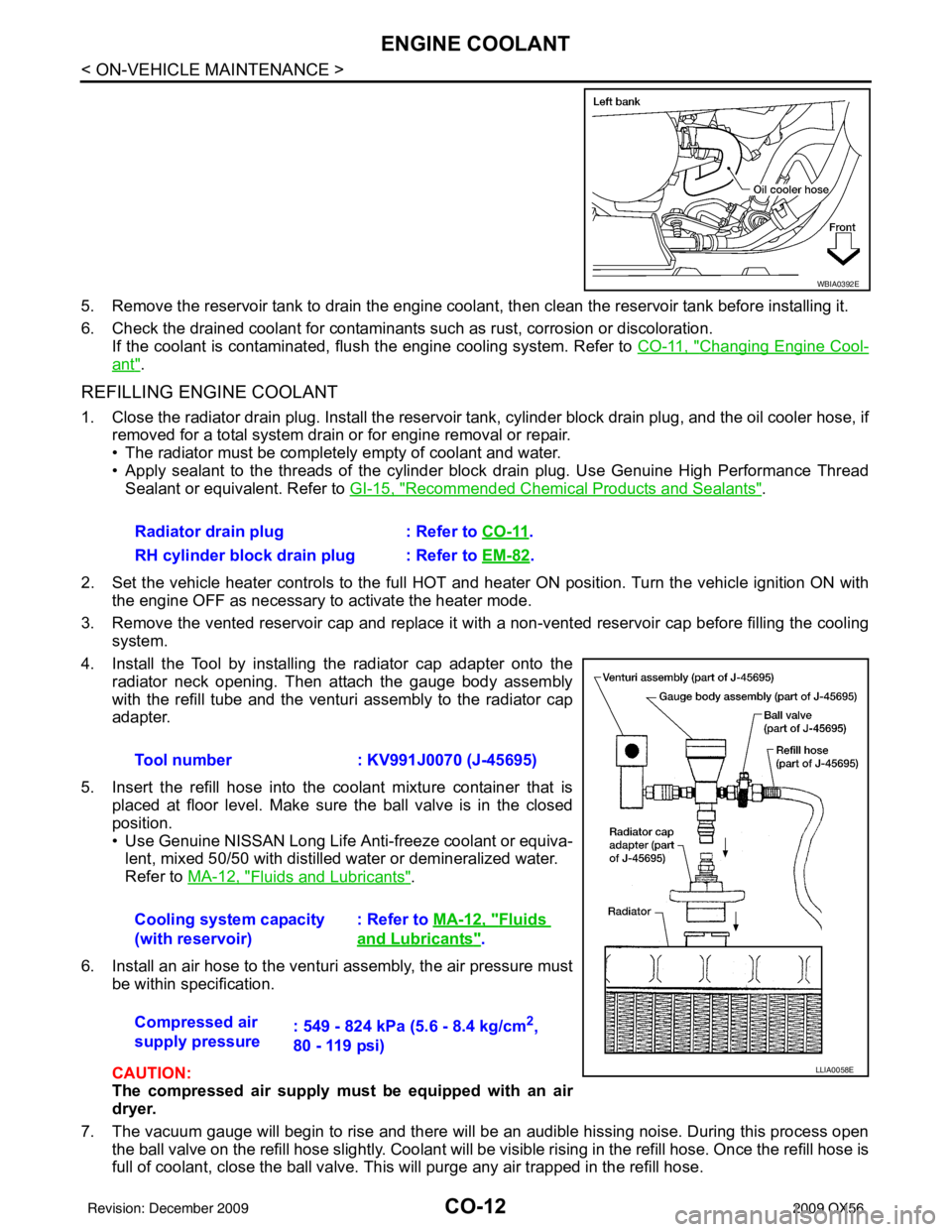
4. Install the Tool by installing the radiator cap adapter onto the radiator neck opening. Then attach the gauge body assembly
with the refill tube and the venturi assembly to the radiator cap
adapter.
5. Insert the refill hose into the coolant mixture container that is placed at floor level. Make sure the ball valve is in the closed
position.
• Use Genuine NISSAN Long Life Anti-freeze coolant or equiva-lent, mixed 50/50 with distilled water or demineralized water.
Refer to MA-12, "
Fluids and Lubricants".
6. Install an air hose to the venturi assembly, the air pressure must be within specification.
CAUTION:
The compressed air supply must be equipped with an air
dryer.
7. The vacuum gauge will begin to rise and there will be an audible hissing noise. During this process open the ball valve on the refill hose slightly. Coolant will be vi sible rising in the refill hose. Once the refill hose is
full of coolant, close the ball valve. This will purge any air trapped in the refill hose.
WBIA0392E
Radiator drain plug : Refer to CO-11.
RH cylinder block drain plug : Refer to EM-82
.
Tool number : KV991J0070 (J-45695)
Cooling system capacity
(with reservoir) : Refer to
MA-12, "
Fluids
and Lubricants".
Compressed air
supply pressure : 549 - 824 kPa (5.6 - 8.4 kg/cm
2,
80 - 119 psi)
LLIA0058E
Revision: December 20092009 QX56
Page 762 of 4171

CO-18
< ON-VEHICLE REPAIR >
ENGINE COOLING FAN
ENGINE COOLING FAN
Exploded ViewINFOID:0000000004129533
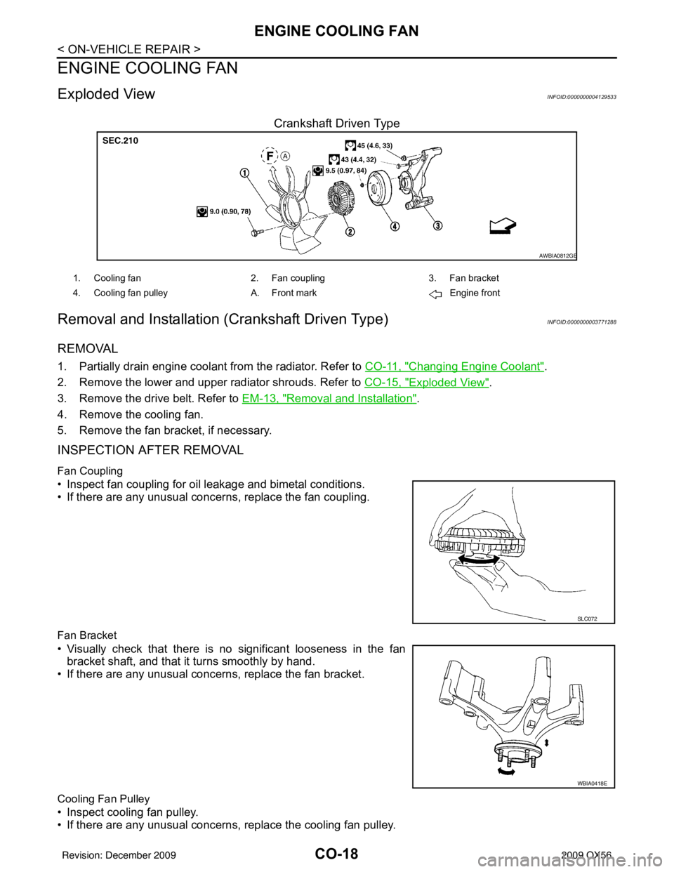
Crankshaft Driven Type
Removal and Installation (Crankshaft Driven Type)INFOID:0000000003771288
REMOVAL
1. Partially drain engine coolant from the radiator. Refer to CO-11, "Changing Engine Coolant".
2. Remove the lower and upper radiator shrouds. Refer to CO-15, "
Exploded View".
3. Remove the drive belt. Refer to EM-13, "
Removal and Installation".
4. Remove the cooling fan.
5. Remove the fan bracket, if necessary.
INSPECTION AFTER REMOVAL
Fan Coupling
• Inspect fan coupling for oil leakage and bimetal conditions.
• If there are any unusual concerns, replace the fan coupling.
Fan Bracket
• Visually check that there is no significant looseness in the fan bracket shaft, and that it turns smoothly by hand.
• If there are any unusual concerns, replace the fan bracket.
Cooling Fan Pulley
• Inspect cooling fan pulley.
• If there are any unusual concerns, replace the cooling fan pulley.
AWBIA0812GB
1. Cooling fan 2. Fan coupling3. Fan bracket
4. Cooling fan pulley A. Front mark Engine front
SLC072
WBIA0418E
Revision: December 20092009 QX56
Page 811 of 4171

REAR WINDOW DEFOGGERDEF-43
< ON-VEHICLE REPAIR >
C
DE
F
G H
I
J
K
M A
B
DEF
N
O P
ON-VEHICLE REPAIR
REAR WINDOW DEFOGGER
Filament CheckINFOID:0000000003776364
1. When measuring voltage, wrap tin foil around the top of the neg- ative probe.Then press the foil against the wire with your finger.
2. Attach probe circuit tester (in Volt range) to middle portion of each filament.
3. If a filament is burned out, circuit tester registers 0 or battery voltage.
4. To locate burned out point, move probe to left and right along fil- ament. Test needle will swing abruptly when probe passes the
point.
Filament RepairINFOID:0000000003776365
REPAIR EQUIPMENT
• Conductive silver composition (DuPont No. 4817 or equivalent)
• Ruler 30 cm (11.8 in) long
SEL122R
SEL263
SEL265
Revision: December 20092009 QX56
Page 1044 of 4171
![INFINITI QX56 2009 Factory User Guide DLK-232
< ON-VEHICLE REPAIR >[WITH INTELLIGENT KEY SYSTEM]
HOOD
4. Install the primary and secondary cables securely to the hood
lock.
5. Install the hood lock and the secondary hood lock release asse INFINITI QX56 2009 Factory User Guide DLK-232
< ON-VEHICLE REPAIR >[WITH INTELLIGENT KEY SYSTEM]
HOOD
4. Install the primary and secondary cables securely to the hood
lock.
5. Install the hood lock and the secondary hood lock release asse](/img/42/57031/w960_57031-1043.png)
DLK-232
< ON-VEHICLE REPAIR >[WITH INTELLIGENT KEY SYSTEM]
HOOD
4. Install the primary and secondary cables securely to the hood
lock.
5. Install the hood lock and the secondary hood lock release assemblies.
6. Check the hood lock adjustment and hood opener operation. Refer to DLK-229, "
Fitting Adjustment".
7. Install the remaing componets in the reverse order of removal.
Hood Lock Control InspectionINFOID:0000000003775854
CAUTION:
If the hood lock cable is bent or deformed, replace it.
1. Remove the front grille. Refer to EXT-17, "
Removal and Installation".
2. Make sure the secondary latch is properly engaged with the sec- ondary striker with hood's own weight by dropping it from
approx. 200 mm (7.87 in) height.
3. While operating the hood opener, carefully make sure the front end of the hood is raised by approx. 20 mm (0.79 in). Also make
sure the hood opener returns to the original position.
4. Check the hood lock lubrication condition. If necessary, apply “body grease” to the points shown in the figure.
5. Install the front grille. Refer to EXT-17, "
Removal and Installa-
tion".
Hood Stay DisposalINFOID:0000000005877751
1. Fix hood stay (1) using a vise (C).
2. Using hacksaw (A) slowly make 2 holes in the hood stay, in numerical order as shown in the figure.
CAUTION:
• When cutting a hole on hood stay, always cover a hack-saw using a shop cloth (B) to avoid scattering metal frag-
ments or oil.
• Wear eye protection (safety glasses).
• Wear gloves.
PIIA0174E
PIIA1086E
PIIA0176E
JMKIA3336ZZ
Revision: December 20092009 QX56
Page 1060 of 4171

DLN-4
Precaution Necessary for Steering Wheel Rota-
tion After Battery Disconnect .................................
191
PREPARATION ..........................................193
PREPARATION .............................................. .193
Commercial Service Tool .................................... ..193
SYMPTOM DIAGNOSIS ............................194
NOISE, VIBRATION, AND HARSHNESS
(NVH) TROUBLESHOOTING ......................... .
194
NVH Troubleshooting Chart ................................ ..194
ON-VEHICLE REPAIR ............................. ..195
PROPELLER SHAFT ..................................... .195
On-Vehicle Service .............................................. ..195
REMOVAL AND INSTALLATION ..............196
PROPELLER SHAFT ..................................... .196
Removal and Installation ..................................... ..196
DISASSEMBLY AND ASSEMBLY ............199
PROPELLER SHAFT ..................................... .199
Disassembly and Assembly ................................. ..199
SERVICE DATA AND SPECIFICATIONS
(SDS) .............. ............................................
201
SERVICE DATA AND SPECIFICATIONS
(SDS) ............................................................... .
201
General Specification .......................................... ..201
Snap Ring ..............................................................201
FRONT FINAL DRIVE: M205
PRECAUTION ....... ....................... ..............
203
PRECAUTIONS .............................................. .203
Precaution for Supplemental Restraint System
(SRS) "AIR BAG" and "SEAT BELT PRE-TEN-
SIONER" .............................................................. ..
203
Precaution Necessary for Steering Wheel Rota-
tion After Battery Disconnect .................................
203
Precaution for Servicing Front Final Drive .............204
PREPARATION ..........................................205
PREPARATION .............................................. .205
Special Service Tool ............................................ ..205
Commercial Service Tool ......................................207
SYMPTOM DIAGNOSIS ............................208
NOISE, VIBRATION AND HARSHNESS
(NVH) TROUBLESHOOTING ......................... .
208
NVH Troubleshooting Chart ................................ ..208
ON-VEHICLE MAINTENANCE ..................209
DIFFERENTIAL GEAR OIL ............................ ..209
Changing Differential Gear Oil ............................. .209
Checking Differential Gear Oil ..............................209
ON-VEHICLE REPAIR ..............................210
SIDE OIL SEAL .............................................. ..210
Removal and Installation ...................................... .210
FRONT OIL SEAL ............................................211
Removal and Installation ...................................... .211
CARRIER COVER .......................................... ..214
Removal and Installation ...................................... .214
REMOVAL AND INSTALLATION .............215
FRONT FINAL DRIVE .................................... ..215
Removal and Installation ...................................... .215
DISASSEMBLY AND ASSEMBLY ...........217
FRONT FINAL DRIVE .................................... ..217
Disassembly and Assembly ................................. .217
SERVICE DATA AND SPECIFICATIONS
(SDS) ............... ..........................................
234
SERVICE DATA AND SPECIFICATIONS
(SDS) .............................................................. ..
234
General Specification ........................................... .234
Inspection and Adjustment ....................................234
REAR FINAL DRIVE: R230
PRECAUTION ............... ............................
236
PRECAUTIONS .............................................. ..236
Precaution for Supplemental Restraint System
(SRS) "AIR BAG" and "SEAT BELT PRE-TEN-
SIONER" .............................................................. .
236
Precaution Necessary for Steering Wheel Rota-
tion After Battery Disconnect ................................
236
Precaution for Servicing Rear Final Drive .............237
PREPARATION .........................................238
PREPARATION .............................................. ..238
Special Service Tool ............................................ .238
Commercial Service Tool ......................................240
SYMPTOM DIAGNOSIS ...........................242
NOISE, VIBRATION AND HARSHNESS
(NVH) TROUBLESHOOTING ......................... ..
242
NVH Troubleshooting Chart ................................. .242
DESCRIPTION ..................................................243
Cross-Sectional View ........................................... .243
ON-VEHICLE MAINTENANCE .................244
DIFFERENTIAL GEAR OIL ............................ ..244
Revision: December 20092009 QX56
Page 1061 of 4171

DLN-5
CEF
G H
I
J
K L
M A
B
DLN
N
O P
Changing Differential Gear Oil ............................
..
244
Checking Differential Gear Oil ...............................244
ON-VEHICLE REPAIR ...............................245
FRONT OIL SEAL .......................................... ..245
Removal and Installation ..................................... ..245
SIDE OIL SEAL ................................................247
Removal and Installation ..................................... ..247
CARRIER COVER .......................................... ..249
Removal and Installation ..................................... ..249
REMOVAL AND INSTALLATION .............250
REAR FINAL DRIVE .......................................250
Removal and Installation ..................................... ..250
DISASSEMBLY AND ASSEMBLY ............253
REAR FINAL DRIVE .......................................253
Disassembly and Assembly ................................. ..253
SERVICE DATA AND SPECIFICATIONS
(SDS) ............... ...........................................
270
SERVICE DATA AND SPECIFICATIONS
(SDS) ...............................................................
270
General Specification .......................................... ..270
Inspection and Adjustment ....................................270
Revision: December 20092009 QX56