check oil INFINITI QX56 2009 Factory Service Manual
[x] Cancel search | Manufacturer: INFINITI, Model Year: 2009, Model line: QX56, Model: INFINITI QX56 2009Pages: 4171, PDF Size: 84.65 MB
Page 3794 of 4171

TM-146
< SYMPTOM DIAGNOSIS >
SYSTEM SYMPTOM
Check the A/T fluid level. Refer to TM-179, "Checking the A/T Fluid
(ATF)".
OK or NG
OK >> GO TO 3.
NG >> Refill ATF.
3.CHECK CONTROL CABLE
Check the control cable.
Refer to TM-195, "Checking of A/T Position"
.
OK or NG
OK >> GO TO 4.
NG >> Adjust control cable. Refer to TM-195, "Adjustment of A/
T Position".
4.CHECK A/T FLUID CONDITION
1. Remove oil pan. Refer to TM-201, "Oil Pan"
.
2. Check A/T fluid condition. Refer to TM-179, "Checking the A/T
Fluid (ATF)".
OK or NG
OK >> GO TO 5.
NG >> GO TO 8.
5.DETECT MALFUNCTIONING ITEM
Check the malfunction items. If any items are dam aged, repair or replace damaged parts. Refer to TM-152,
"Symptom Table" (Symptom No.15).
OK or NG
OK >> GO TO 6.
NG >> Repair or replace damaged parts.
6.CHECK SYMPTOM
Check again. Refer to TM-194, "Cruise Test - Part 3"
.
OK or NG
OK >> INSPECTION END
NG >> GO TO 7.
7.PERFORM TCM INSPECTION
1. Perform TCM input/output signals inspection. Refer to TM-104, "Reference Value"
.
2. If NG, recheck A/T assembly harness connector terminals for damage or loose connection with harness
connector.
OK or NG
OK >> INSPECTION END
SAT638A
LCIA0345E
SCIA5199E
Revision: December 20092009 QX56
Page 3795 of 4171

SYSTEM SYMPTOMTM-147
< SYMPTOM DIAGNOSIS >
CEF
G H
I
J
K L
M A
B
TM
N
O P
NG >> Repair or replace damaged parts.
8.DETECT MALFUNCTIONING ITEM
Check the malfunction items. If any items are damaged, repair or replace damaged parts. Refer to TM-152,
"Symptom Table" (Symptom No.15).
OK or NG
OK >> GO TO 6.
NG >> Repair or replace damaged parts.
A/T Does Not Shift: 3GR → 2GRINFOID:0000000003772009
SYMPTOM:
When shifted from 33 to 22 position, does not downshift from 3GR to 2GR.
DIAGNOSTIC PROCEDURE
1.CHECK SELF-DIAGNOSIS RESULTS
Perform self-diagnosis. Refer to TM-32, "CONSULT-III Function (TRANSMISSION)"
.
Do the self-diagnosis results i ndicate transmission range switch?
YES >> Check the malfunctioning system. Refer to TM-44, "Diagnosis Procedure".
NO >> GO TO 2.
2.CHECK A/T FLUID LEVEL
Check the A/T fluid level. Refer to TM-179, "Checking the A/T Fluid
(ATF)".
OK or NG
OK >> GO TO 3.
NG >> Refill ATF.
3.CHECK CONTROL CABLE
Check the control cable.
Refer to TM-195, "Checking of A/T Position"
.
OK or NG
OK >> GO TO 4.
NG >> Adjust control cable. Refer to TM-195, "Adjustment of A/
T Position".
4.CHECK A/T FLUID CONDITION
1. Remove oil pan. Refer to TM-201, "Oil Pan"
.
SAT638A
LCIA0345E
Revision: December 20092009 QX56
Page 3797 of 4171

SYSTEM SYMPTOMTM-149
< SYMPTOM DIAGNOSIS >
CEF
G H
I
J
K L
M A
B
TM
N
O P
Without CONSULT-III
1. Turn ignition switch “ON”.(Do not start engine)
2. Check voltage between A/T shift selector harness connector ter- minal and ground.
OK or NG
OK >> GO TO 3.
NG >> Repair or replace damaged parts.
3.CHECK A/T FLUID LEVEL
Check the A/T fluid level. Refer to TM-179, "Checking the A/T Fluid
(ATF)".
OK or NG
OK >> GO TO 4.
NG >> Refill ATF.
4.CHECK CONTROL CABLE
Check the control cable.
Refer to TM-195, "Checking of A/T Position"
.
OK or NG
OK >> GO TO 5.
NG >> Adjust control cable. Refer to TM-195, "Adjustment of A/
T Position".
5.CHECK A/T FLUID CONDITION
1. Remove oil pan. Refer to TM-201, "Oil Pan"
.
Monitor item Condition Display value
1 POSITION SWWhen setting the selector
lever to "1" position.
ON
When setting selector le-
ver to other positions. OFF
Item Connector No. Terminal No. Condition Data
(Approx.)
1st position switch M203 7 - Ground When setting
the selector le-
ver to "1" posi-
tion.
0V
When setting
selector lever
to other posi-
tions. Battery voltage
AWDIA0811ZZ
SAT638A
LCIA0345E
Revision: December 20092009 QX56
Page 3799 of 4171

SYSTEM SYMPTOMTM-151
< SYMPTOM DIAGNOSIS >
CEF
G H
I
J
K L
M A
B
TM
N
O P
Without CONSULT-III
1. Turn ignition switch “ON”.(Do not start engine)
2. Check voltage between A/T shift selector harness connector ter- minal and ground.
OK or NG
OK >> GO TO 3.
NG >> Repair or replace damaged parts.
3.CHECK A/T FLUID LEVEL
Check the A/T fluid level. Refer to TM-179, "Checking the A/T Fluid
(ATF)".
OK or NG
OK >> GO TO 4.
NG >> Refill ATF.
4.CHECK CONTROL CABLE
Check the control cable.
Refer to TM-195, "Checking of A/T Position"
.
OK or NG
OK >> GO TO 5.
NG >> Adjust control cable. Refer to TM-195, "Adjustment of A/
T Position".
5.CHECK A/T FLUID CONDITION
1. Remove oil pan. Refer to TM-201, "Oil Pan"
.
Monitor item Condition Display value
1 POSITION SWWhen setting the selector
lever to "1" position.
ON
When setting selector le-
ver to other positions. OFF
Item Connector No. Terminal No. Condition Data
(Approx.)
1st position switch M203 7 - Ground When setting
the selector le-
ver to "1" posi-
tion.
0V
When setting
selector lever
to other posi-
tions. Battery voltage
AWDIA0811ZZ
SAT638A
LCIA0345E
Revision: December 20092009 QX56
Page 3823 of 4171

PRECAUTIONSTM-175
< PRECAUTION >
CEF
G H
I
J
K L
M A
B
TM
N
O P
5. When the repair work is completed, return the ignition switch to the ″LOCK ″ position before connecting
the battery cables. (At this time, the steering lock mechanism will engage.)
6. Perform a self-diagnosis check of al l control units using CONSULT-III.
Precaution for On Board Diagnosis (OBD) System of A/T and EngineINFOID:0000000003772014
The ECM has an on board diagnostic system. It will light up the malfunction indicator lamp (MIL) to warn the
driver of a malfunction causing emission deterioration.
CAUTION:
Be sure to turn the ignition sw itch “OFF” and disconnect the negati ve battery cable before any repair
or inspection work. The open/short circuit of related switches, sensors, solenoid valves, etc. Will
cause the MIL to light up.
Be sure to connect and lock the connectors secure ly after work. A loose (unlocked) connector will
cause the MIL to light up due to an open circuit. (Be sure the connector is free from water, grease,
dirt, bent terminals, etc.)
Be sure to route and secure the harnesses properly after work. Interference of the harness with a
bracket, etc. May cause the MIL to li ght up due to a short circuit.
Be sure to connect rubber tubes properly afte r work. A misconnected or disconnected rubber tube
may cause the MIL to light up due to a malfunction of the EGR system or fuel injection system, etc.
Be sure to erase the unnecessary malfunction informa tion (repairs completed) from the TCM and
ECM before returning the vehicle to the customer.
PrecautionINFOID:0000000003772015
NOTE:
If any malfunctions occur in th e RE5R05A model transmission, repl ace the entire transmission assem-
bly.
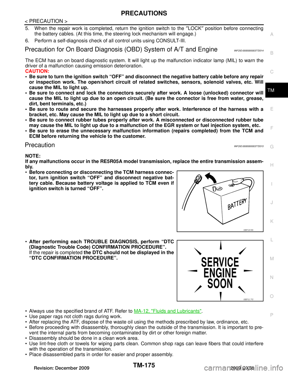
Before connecting or disconn ecting the TCM harness connec-
tor, turn ignition switch “O FF” and disconnect negative bat-
tery cable. Because battery voltage is applied to TCM even if
ignition switch is turned “OFF”.
After performing each TROUBL E DIAGNOSIS, perform “DTC
(Diagnostic Trouble Code) CONFIRMATION PROCEDURE”.
If the repair is completed the DTC should not be displayed in the
“DTC CONFIRMATION PROCEDURE”.
Always use the specified brand of ATF. Refer to MA-12, "Fluids and Lubricants"
.
Use paper rags not cloth rags during work.
After replacing the ATF, dispose of the waste oil using the methods prescribed by law, ordinance, etc.
Before proceeding with disassembly, thoroughly clean the outsi de of the transmission. It is important to pre-
vent the internal parts from becoming contaminated by dirt or other foreign matter.
Disassembly should be done in a clean work area.
Use lint-free cloth or towels for wiping parts clean. Common shop rags can leave fibers that could interfere
with the operation of the transmission.
Place disassembled parts in order for easier and proper assembly.
SEF289H
SEF217U
Revision: December 20092009 QX56
Page 3824 of 4171

TM-176
< PRECAUTION >
PRECAUTIONS
All parts should be carefully cleaned with a general purpose, non-flammable solvent before inspection orreassembly.
Gaskets, seals and O-rings should be replaced any time the transmission is disassembled.
It is very important to perform functional tests whenever they are indicated.
The valve body contains precision parts and requires extreme care when parts are removed and serviced. Place disassembled valve body parts in order for easier and proper assembly. Care will also prevent springs
and small parts from becoming scattered or lost.
Properly installed valves, sleeves, plugs, etc. will s lide along bores in valve body under their own weight.
Before assembly, apply a coat of recommended ATF to all parts. Apply petroleum jelly to protect O-rings and
seals, or hold bearings and washers in place during assembly. Do not use grease.
Extreme care should be taken to avoid damage to O-rings, seals and gaskets when assembling.
Clean or replace ATF cooler if excessive foreign material is found in oil pan or clogging strainer. Refer to TM-
183, "A/T Fluid Cooler Cleaning".
After overhaul, refill the transmission with new ATF.
When the A/T drain plug is removed, only some of the fluid is drained. Old A/T fluid will remain in torque con- verter and ATF cooling system.
Always follow the procedures under “Changing A/T Fluid” in the AT section when changing A/T fluid. Refer to
TM-181, "Changing the A/T Fluid (ATF)"
.
Service Notice or PrecautionINFOID:0000000003772016
ATF COOLER SERVICE
If A/T fluid contains fictional material (clutches, bands, etc.), or if an A/T is repaired, overhauled, or replaced,
inspect and clean the A/T fluid cooler mounted in the radiat or or replace the radiator. Flush cooler lines with
cleaning solvent and compressed air after repair. For A/T fluid cooler cleaning procedure, refer to TM-183,
"A/T Fluid Cooler Cleaning". For radiator replacement, refer to CO-15, "Removal and Installation".
CHECKING AND CHANGING A/T FLUID
Increase ATF oil temperature to 80 °C (176 °F) first, then check and adjust oil level at 65 °C (149 °F).
NOTE:
The A/T has both water cooling and air cooling systems . The air cooling system has a bypass valve. When
ATF oil temperature is at or below 50 °C (122 °F), it does not flow through the air cooled system. If A/T oil
level is adjusted without flow throughout the entir e system, the level will be 10mm lower than required.
Therefore, all piping should be filled with oil when adjusting level.
OBD-II SELF-DIAGNOSIS
A/T self-diagnosis is performed by the TCM in combination with the ECM. Refer to the table on TM-32,
"CONSULT-III Function (TRANSMISSION)" for the indicator used to display each self-diagnostic result.
The self-diagnostic results indicated by the MIL ar e automatically stored in both the ECM and TCM memo-
ries.
Always perform the procedure on TM-30, "OBD-II Diagnostic Trouble Code (DTC)"
to complete the
repair and avoid unnecessary blinking of the MIL.
For details of OBD-II, refer to TM-30
.
Certain systems and components, especially those related to OBD, may use the new style slide-
locking type harness connector. For descrip tion and how to disconnect, refer to PG-68
.
Revision: December 20092009 QX56
Page 3829 of 4171

A/T FLUIDTM-181
< ON-VEHICLE MAINTENANCE >
CEF
G H
I
J
K L
M A
B
TM
N
O P
Changing the A/T Fluid (ATF)INFOID:0000000005892327
CAUTION:
If using the vehicle for towing, the A/T fl uid must be replaced as specified. Refer to MA-8, "Introduc-
tion of Periodic Maintenance".
1. Drive the vehicle to warm up the A/T fluid to approximately 80 ° C (176 ° F).
2. Stop the engine.
3. Remove the A/T fluid level gauge.
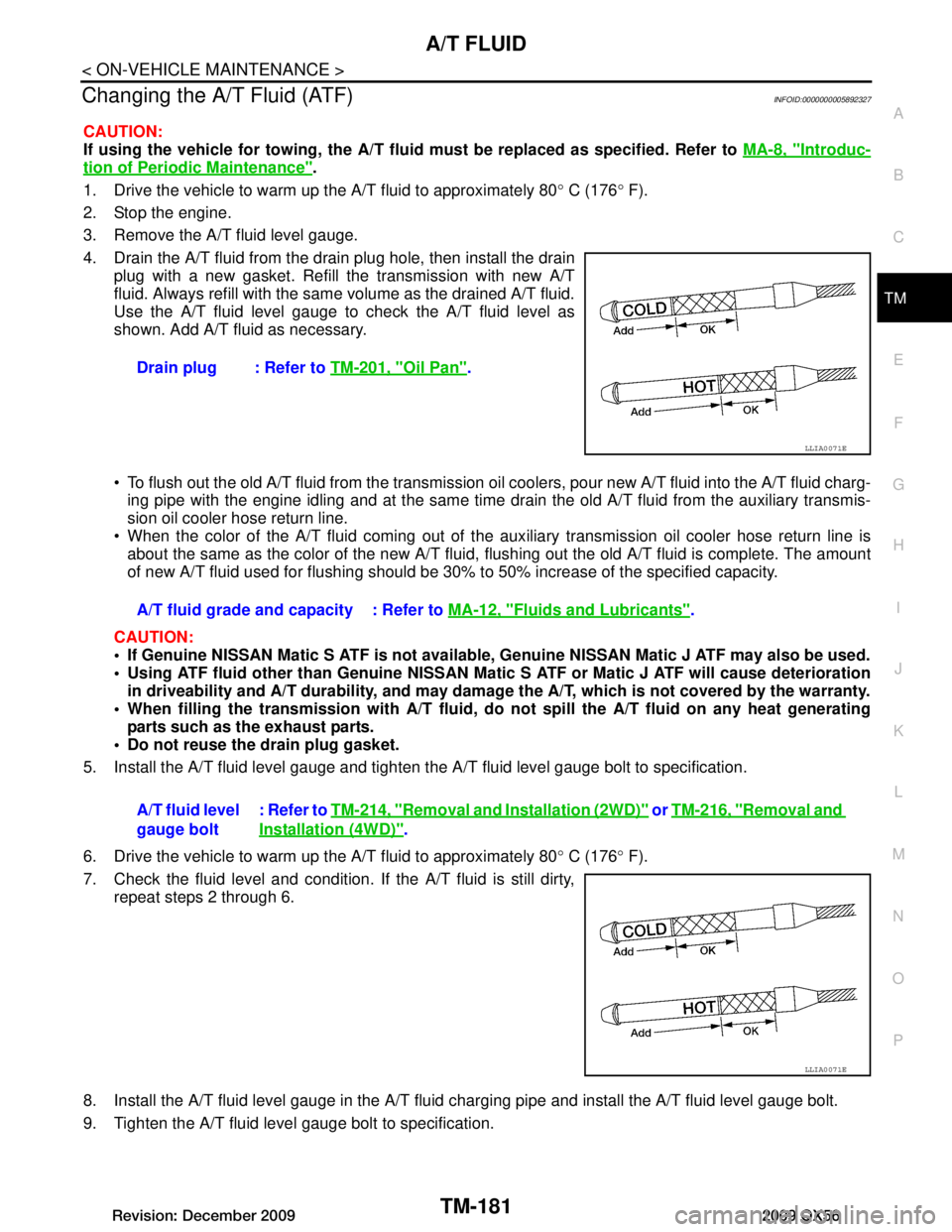
4. Drain the A/T fluid from the drai n plug hole, then install the drain
plug with a new gasket. Refill the transmission with new A/T
fluid. Always refill with the same volume as the drained A/T fluid.
Use the A/T fluid level gauge to check the A/T fluid level as
shown. Add A/T fluid as necessary.
To flush out the old A/T fluid from the transmission o il coolers, pour new A/T fluid into the A/T fluid charg-
ing pipe with the engine idling and at the same time drain the old A/T fluid from the auxiliary transmis-
sion oil cooler hose return line.
When the color of the A/T fluid coming out of the aux iliary transmission oil cooler hose return line is
about the same as the color of the new A/T fluid, flushing out the old A/T fluid is complete. The amount
of new A/T fluid used for flushing should be 30% to 50% increase of the specified capacity.
CAUTION:
If Genuine NISSAN Matic S ATF is not available, Genuine NISSAN Matic J ATF may also be used.
Using ATF fluid other than Genuine NISSAN Matic S ATF or Matic J ATF will cause deterioration
in driveability and A/T durability, and may damage the A/T, which is not covered by the warranty.
When filling the transmission with A/T fluid, do not spill the A/T fluid on any heat generating
parts such as the exhaust parts.
Do not reuse the drain plug gasket.
5. Install the A/T fluid level gauge and tighten t he A/T fluid level gauge bolt to specification.
6. Drive the vehicle to warm up the A/T fluid to approximately 80 ° C (176 ° F).
7. Check the fluid level and condition. If the A/T fluid is still dirty, repeat steps 2 through 6.
8. Install the A/T fluid level gauge in the A/T fluid charging pipe and install the A/T fluid level gauge bolt.
9. Tighten the A/T fluid level gauge bolt to specification. Drain plug : Refer to
TM-201, "Oil Pan"
.
LLIA0071E
A/T fluid grade and capacity : Refer to MA-12, "Fluids and Lubricants".
A/T fluid level
gauge bolt : Refer to
TM-214, "Removal and Installation (2WD)"
or TM-216, "Removal and
Installation (4WD)".
LLIA0071E
Revision: December 20092009 QX56
Page 3834 of 4171

TM-186
< ON-VEHICLE MAINTENANCE >
STALL TEST
STALL TEST
Inspection and JudgmentINFOID:0000000003772024
A/T FLUID CHECK
Fluid Leakage and Fluid Level Check
Inspect for fluid leakage and check the fluid level. Refer to TM-179, "Checking the A/T Fluid (ATF)".
Fluid Condition Check
Inspect the fluid condition.
STALL TEST
Stall Test Procedure
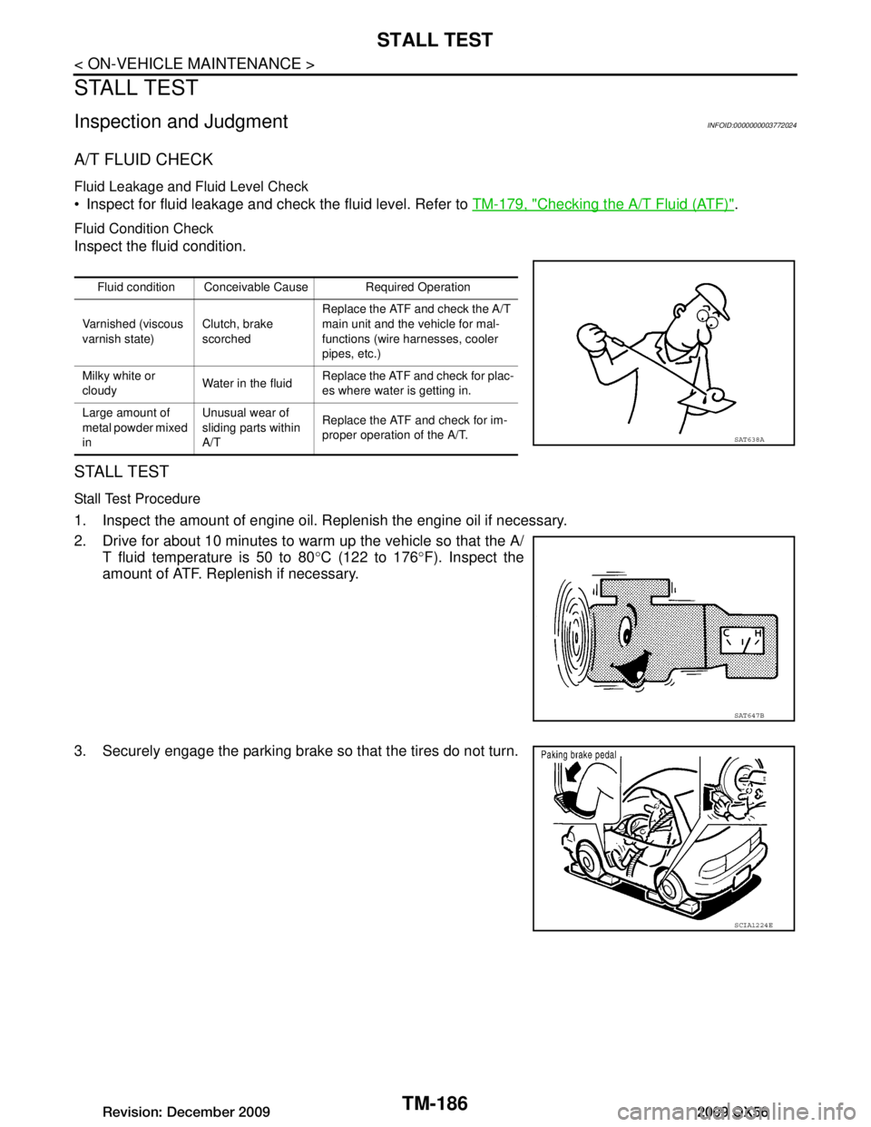
1. Inspect the amount of engine oil. Replenish the engine oil if necessary.
2. Drive for about 10 minutes to warm up the vehicle so that the A/
T fluid temperature is 50 to 80 °C (122 to 176 °F). Inspect the
amount of ATF. Replenish if necessary.
3. Securely engage the parking brake so that the tires do not turn.
Fluid condition Conceivable Cause Required Operation
Varnished (viscous
varnish state) Clutch, brake
scorchedReplace the ATF and check the A/T
main unit and the vehicle for mal-
functions (wire harnesses, cooler
pipes, etc.)
Milky white or
cloudy Water in the fluidReplace the ATF and check for plac-
es where water is getting in.
Large amount of
metal powder mixed
in Unusual wear of
sliding parts within
A/T
Replace the ATF and check for im-
proper operation of the A/T.
SAT638A
SAT647B
SCIA1224E
Revision: December 20092009 QX56
Page 3839 of 4171

ROAD TESTTM-191
< ON-VEHICLE MAINTENANCE >
CEF
G H
I
J
K L
M A
B
TM
N
O P
YES >> Enter a check mark at “In “P” Position V ehicle Moves When Pushed” on the diagnostics work-
sheet, then continue the road test.
NO >> GO TO 4.
4.CHECK “N” POSITION FUNCTIONS
1. Start the engine.
2. Move selector lever to “N” position.
3. Release the parking brake.
Does vehicle move forward or backward?
YES >> Enter a check mark at “In “N” Position Ve hicle Moves” on the diagnostics worksheet, then con-
tinue the road test.
NO >> GO TO 5.
5.CHECK SHIFT SHOCK
1. Engage the brake.
2. Move selector lever to “D” position.
When the transmission is shifted from
“N” to “D”, is there an excessive shock?
YES >> Enter a check mark at “Large Shock ("N" to "D" Position) on the diagnostics worksheet, then con-
tinue the road test.
NO >> GO TO 6.
6.CHECK “R” POSITION FUNCTIONS
1. Engage the brake.
2. Move selector lever to “R” position.
3. Release the brake for 4 to 5 seconds.
Does the vehicle creep backward?
YES >> GO TO 7.
NO >> Enter a check mark at “Vehicle Does Not Creep Backward In "R" Position” on the diagnostics worksheet, then continue the road test.
7.CHECK “D” POSITION FUNCTIONS
Inspect whether the vehicle creeps forward when the transmission is put into the “D” position.
Does the vehicle creep forward in the
“D” positions?
YES >> Go to TM-191, "Cruise Test - Part 1", TM-193, "Cruise Test - Part 2", and TM-194, "Cruise Test -
Part 3".
NO >> Enter a check mark at “Vehicle Does Not Creep Forward in "D" Position” on the diagnostics work- sheet, then continue the road test.
Cruise Test - Part 1INFOID:0000000003772029
1.CHECK STARTING OUT FROM D1
1. Drive the vehicle for about 10 minutes to warm up the engine oil and ATF. Appropriate temperature for the ATF: 50 - 80 °C (122 - 176 °F)
2. Park the vehicle on a level surface.
3. Move selector lever to “P” position.
4. Start the engine.
5. Move selector lever to “D” position.
6. Press the accelerator pedal about half way down to accelerate the vehicle.
With CONSULT-III
Read off the gear positions.
Starts from D1?
YES >> GO TO 2.
NO >> Enter a check mark at “Vehicle Cannot be Started From D1” on the diagnostics worksheet, then
continue the road test.
2.CHECK SHIFT-UP D1 → D2
Press down the accelerator pedal about half way and inspect if the vehicle shifts up (D1 → D2) at the appropri-
ate speed.
Revision: December 20092009 QX56
Page 3849 of 4171

OIL PANTM-201
< ON-VEHICLE REPAIR >
CEF
G H
I
J
K L
M A
B
TM
N
O P
OIL PAN
Oil PanINFOID:0000000005880214
REMOVAL AND INSTALLATION
Removal
1. Drain A/T fluid. Refer to TM-181, "Changing the A/T Fluid (ATF)".
2. Remove oil pan clips (1).
3. Remove oil pan (2).
4. Remove oil pan gasket. : Vehicle front
: Oil pan bolts
Drain plug (3)
5. Check foreign materials in oil pan to help determine c ause of malfunction. If the A/T fluid is very dark, has
some burned smell, or contains foreign particles, friction material (clutches, band) may need replacement.
A tacky film that will not wipe clean indicates varnis h build up. Varnish can cause valves, servo, and
clutches to stick and can inhibit pump pressure.
CAUTION:
If friction material is detected, flush th e transmission cooler after repair. Refer to TM-183, "A/T
Fluid Cooler Cleaning".
6. Remove magnets from oil pan.
Installation
1. Install the oil pan magnets as shown.
AWDIA0023ZZ
SCIA5200E
SCIA5200E
Revision: December 20092009 QX56