check transmission fluid INFINITI QX56 2009 Factory Service Manual
[x] Cancel search | Manufacturer: INFINITI, Model Year: 2009, Model line: QX56, Model: INFINITI QX56 2009Pages: 4171, PDF Size: 84.65 MB
Page 1070 of 4171
![INFINITI QX56 2009 Factory Service Manual
DLN-14
< FUNCTION DIAGNOSIS >[ATX14B]
4WD SYSTEM
Displays 4LO condition while engine is running. 4LO indi
cator lamp flashes if transfer gear does not shift
completely under 2WD, AUTO, 4H ⇔4LO. ( INFINITI QX56 2009 Factory Service Manual
DLN-14
< FUNCTION DIAGNOSIS >[ATX14B]
4WD SYSTEM
Displays 4LO condition while engine is running. 4LO indi
cator lamp flashes if transfer gear does not shift
completely under 2WD, AUTO, 4H ⇔4LO. (](/img/42/57031/w960_57031-1069.png)
DLN-14
< FUNCTION DIAGNOSIS >[ATX14B]
4WD SYSTEM
Displays 4LO condition while engine is running. 4LO indi
cator lamp flashes if transfer gear does not shift
completely under 2WD, AUTO, 4H ⇔4LO. (When 4WD warning lamp is turned on, 4LO indicator lamp is
turned off.)
Turns ON for approximately 1 second when ignition switch is turned ON, for purpose of lamp check.
4WD WARNING LAMP
Turns on or flashes when there is a malfunction in 4WD system.
Also turns on when ignition switch is turned ON, for purpose of lamp che\
ck. Turns OFF approximately 1 sec-
ond after the engine starts if system is normal.
4WD Warning Lamp Indication
ATP WARNING LAMP
When the A/T selector lever is in P position, the vehicle may move if the transfer case is in neutral. ATP warn-
ing lamp is turned on to indicate this condition to the driver.
LINE PRESSURE SWITCH
With the transfer system design, cont rol of the oil pressure provides the transmission of drive torque to the
front wheels. The main pressure to control the oil pressure is referred to as the line pressure.
The line pressure switch determines whether or not adequate line pressure has built up under different oper-
ating conditions.
The line pressure switch closes when line pressure is produced.
The line pressure switch senses line pressure abnormalities and turns the 4WD warning lamp ON.
CLUTCH PRESSURE SWITCH
The clutch pressure switch determines whether or not adequate clutch pressure has built up under different
operating conditions.
The clutch pressure switch closes when clutch pressure is produced.
The clutch pressure switch senses clutch pressu re abnormalities and turns the 4WD warning lamp ON.
WAIT DETECTION SWITCH
The wait detection switch operates when there is circulating torque produced in the propeller shaft (L→H) or
when there is a phase difference between 2-4 sleeve and clutch drum (H →L). After the release of the circu-
lating torque, the wait detection switch helps provi de the 4WD lock gear (clutch drum) shifts. A difference
may occur between the operation of the 4WD shift swit ch and actual drive mode. At this point, the wait
detection switch senses an actual drive mode.
The wait detection switch operates as follows.
- 4WD lock gear (clutch drum) locked: ON
- 4WD lock gear (clutch drum) released: OFF
The wait detection switch senses an actual drive mode and the 4WD shift indicator lamp indicates the vehi-
cle drive mode.
ATP SWITCH
ATP switch detects if transfer case is in neutral by the position of the L-H shift fork.
NOTE:
Transfer case may be in neutral when shifting between 4H-4LO.
NEUTRAL-4LO SWITCH
The neutral-4LO switch detects that tr ansfer gear is in neutral or 4LO (or shifting from neutral to 4LO) condi-
tion by L-H shift fork position.
Condition 4WD warning lamp
System normal OFF
Lamp check Turns ON when ignition switch is turned ON.
Turns OFF after engine start.
4WD system malfunction ON
During self-diagnosis Flashes malfunction mode.
Large difference in diameter of front/
rear tires Flashes slow (1 flash / 2 seconds)
(Continues to flash until the ignition switch is turned OFF)
High fluid temperature in transfer case Flashes rapidly (2 flashes / 1 second)
(Continues to flash until fluid temperature returns to normal)
Revision: December 20092009 QX56
Page 1155 of 4171
![INFINITI QX56 2009 Factory Service Manual
TRANSFER CONTROL UNITDLN-99
< ECU DIAGNOSIS > [ATX14B]
C
EF
G H
I
J
K L
M A
B
DLN
N
O P
CAUTION:
If CAN COMM CIRCUIT [U1000] or CONTROL UNIT (CAN) [U1010] is displayed with other DTCs, first perfo INFINITI QX56 2009 Factory Service Manual
TRANSFER CONTROL UNITDLN-99
< ECU DIAGNOSIS > [ATX14B]
C
EF
G H
I
J
K L
M A
B
DLN
N
O P
CAUTION:
If CAN COMM CIRCUIT [U1000] or CONTROL UNIT (CAN) [U1010] is displayed with other DTCs, first perfo](/img/42/57031/w960_57031-1154.png)
TRANSFER CONTROL UNITDLN-99
< ECU DIAGNOSIS > [ATX14B]
C
EF
G H
I
J
K L
M A
B
DLN
N
O P
CAUTION:
If CAN COMM CIRCUIT [U1000] or CONTROL UNIT (CAN) [U1010] is displayed with other DTCs, first perform the trouble
diagnosis for CAN communication line.
If ABS OP SIG [P1830], VDC OP SIG [P1831] or TCS OP SIG [P1832] is displayed, first perform the trouble diagnosis for ABS system.
If VHCL SPEED SEN·AT [P1807] is displayed, firs t perform the trouble diagnosis for A/T system.
NOTE:
If SHIFT ACT POSI SW [P1818] or SHIFT ACT CIR [P1819] is disp layed, first erase self-diagnostic results. (SHIFT ACT POSI SW
[P1818] or SHIFT ACT CIR [P1819] may be displayed after installing transfer control unit or transfer assembly.)
If CL PRES SW [P1827] or LINE PRES SW [P1828] is displayed only while driving in reverse, check the continuity of R position o n
transmission range switch. When there is no malfunction found in the electrical system, check the hydraulic system.
FLASH CODE CHART
[P1826] OIL TEMP SEN Signal voltage from transfer fluid temperature sen-
sor is abnormally high (Transfer fluid temperature is
abnormally low) while driving. Refer to
DLN-67.
[P1827] CLUTCH PRES SW Improper signal from clutch pressure switch is in-
put due to open or short circuit.
Malfunction occurs in clutch pressure switch or
hydraulic circuit. Refer to
DLN-70
.
[P1828] LINE PRES SW Improper signal from line pressure switch is input
due to open or short circuit.
Malfunction occurs in line pressure switch or hy-
draulic circuit. Refer to
DLN-73
.
[P1829] THROTTLE POSI SEN Malfunction is detected in accelerator pedal posi-
tion signal that is output from ECM through CAN
communication.
Signal voltage from accelerator pedal position sensor is abnormally high or low. Refer to
DLN-76
.
[P1830] ABS OP SIG Malfunction is detected in ABS operation signal that
is output from ABS actuator and electric unit (control
unit) through CAN communication. Refer to
DLN-77
.
[P1831] VDC OP SIG Malfunction is detected in VDC operation signal that
is output from ABS actuator and electric unit (control
unit) through CAN communication.
Refer to
DLN-78
.
[P1832] TCS OP SIG Malfunction is detected in TCS operation signal that
is output from ABS actuator and electric unit (control
unit) through CAN communication. Refer to
DLN-79
.
[U1010] CONTROL UNIT (CAN) Detecting error during the initial diagnosis of CAN
controller of transfer control unit. Refer to
DLN-80
DTC CONSULT-III Diagnostic item is detected when... Reference
Flashing pattern Item Diagnostic item is detected when... Reference
2 Vehicle speed signal
(from A/T) Malfunction is detected in output shaft revolution signal
that is output from TCM through CAN communication.
Improper signal is input while driving. Refer to
DLN-26
.
3 Clutch pressure sole-
noid signal Proper voltage is not applied to clutch pressure solenoid
valve due to open or short circuit.
Refer to
DLN-53
.
4 2-4WD solenoid signal Proper voltage is not applied to 2-4WD solenoid valve due
to open or short circuit.
Refer to
DLN-57
.
5 Transfer motor Transfer motor does not operate properly due to open or
short circuit in transfer motor or transfer motor relay. Refer to
DLN-61
.
6 Vehicle speed signal
(from ABS) Malfunction is detected in vehicle speed signal that is out-
put from ABS actuator and elec tric unit (control unit)
through CAN communication.
Improper signal is input while driving. Refer to
DLN-27
.
7 CAN communication Malfunction has been detected from CAN communication
line. Refer to
LAN-51
.
Revision: December 20092009 QX56
Page 1875 of 4171
EM-52
< ON-VEHICLE REPAIR >
TIMING CHAIN
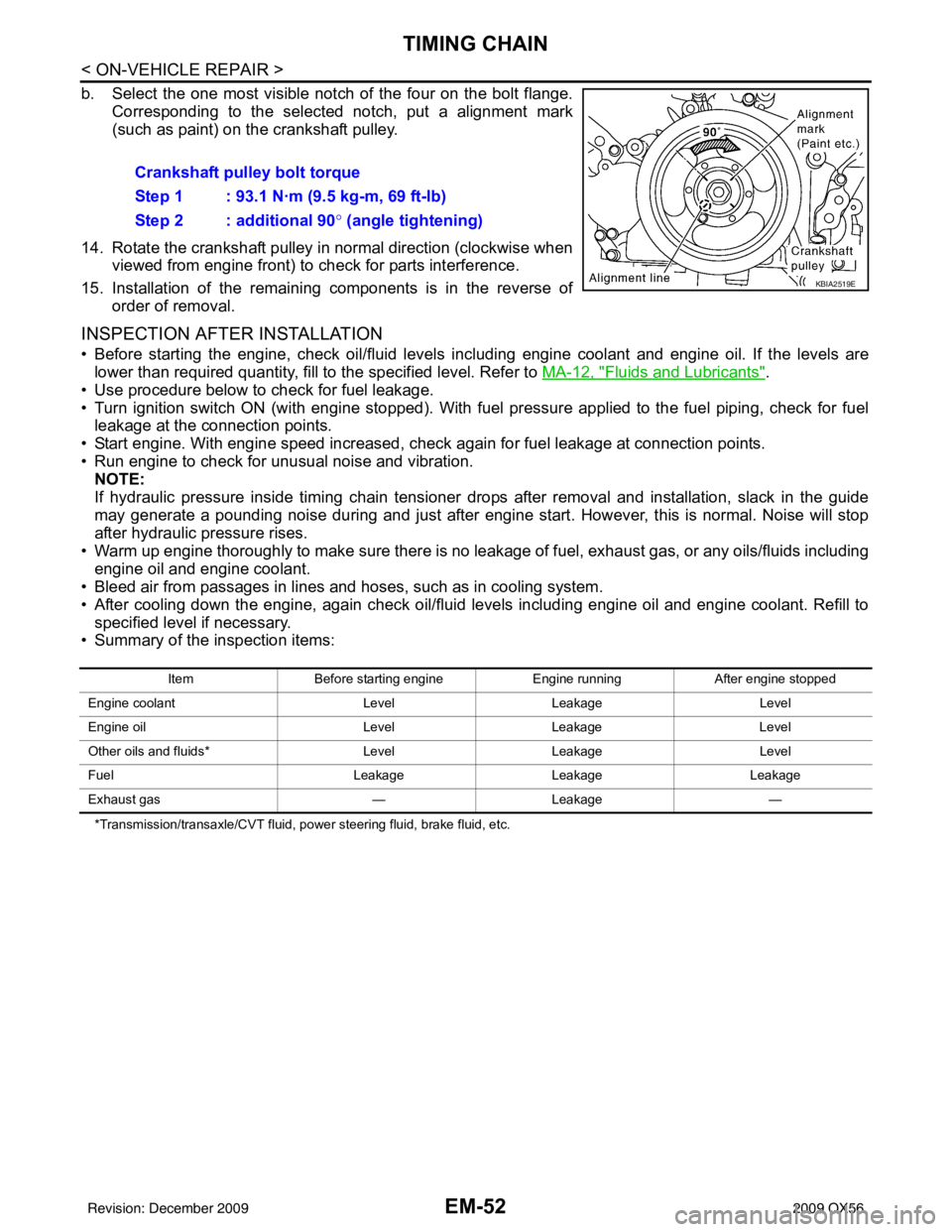
b. Select the one most visible notch of the four on the bolt flange.Corresponding to the selected notch, put a alignment mark
(such as paint) on the crankshaft pulley.
14. Rotate the crankshaft pulley in normal direction (clockwise when viewed from engine front) to check for parts interference.
15. Installation of the remaining components is in the reverse of order of removal.
INSPECTION AFTER INSTALLATION
• Before starting the engine, check oil/fluid levels in cluding engine coolant and engine oil. If the levels are
lower than required quantity, fill to the specified level. Refer to MA-12, "
Fluids and Lubricants".
• Use procedure below to check for fuel leakage.
• Turn ignition switch ON (with engine stopped). With fuel pressure applied to the fuel piping, check for fuel leakage at the connection points.
• Start engine. With engine speed increased, che ck again for fuel leakage at connection points.
• Run engine to check for unusual noise and vibration. NOTE:
If hydraulic pressure inside timing chain tensioner drops after removal and installation, slack in the guide
may generate a pounding noise during and just after engine start. However, this is normal. Noise will stop
after hydraulic pressure rises.
• Warm up engine thoroughly to make sure there is no leakage of fuel, exhaust gas, or any oils/fluids including engine oil and engine coolant.
• Bleed air from passages in lines and hoses, such as in cooling system.
• After cooling down the engine, again check oil/fluid levels including engine oil and engine coolant. Refill to
specified level if necessary.
• Summary of the inspection items:
*Transmission/transaxle/CVT fluid, power steering fluid, brake fluid, etc.
Crankshaft pulley bolt torque
Step 1 : 93.1 N·m (9.5 kg-m, 69 ft-lb)
Step 2 : additional 90 ° (angle tightening)
KBIA2519E
Item Before starting engine Engine runningAfter engine stopped
Engine coolant LevelLeakage Level
Engine oil LevelLeakage Level
Other oils and fluids* LevelLeakage Level
Fuel LeakageLeakageLeakage
Exhaust gas —Leakage —
Revision: December 20092009 QX56
Page 1893 of 4171
EM-70
< ON-VEHICLE REPAIR >
CYLINDER HEAD
• After cooling down the engine, again check oil/fluid levels including engine oil and engine coolant. Refill tospecified level if necessary.
• Summary of the inspection items:
*Transmission/transaxle/CVT fluid, power steering fluid, brake fluid, etc.
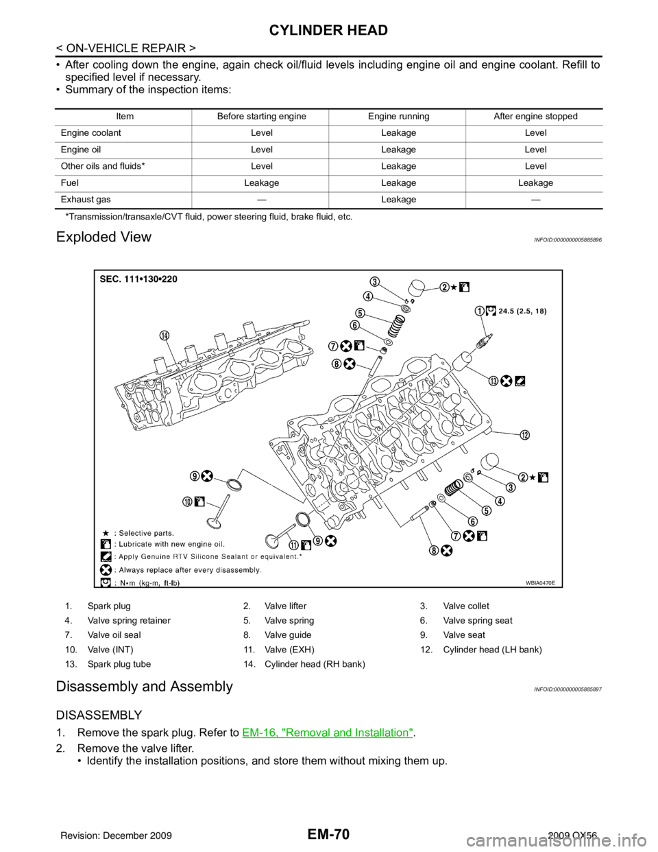
Exploded ViewINFOID:0000000005885896
Disassembly and AssemblyINFOID:0000000005885897
DISASSEMBLY
1. Remove the spark plug. Refer to EM-16, "Removal and Installation".
2. Remove the valve lifter. • Identify the installation positions, and store them without mixing them up.
Item Before starting engine Engine runningAfter engine stopped
Engine coolant LevelLeakage Level
Engine oil LevelLeakage Level
Other oils and fluids* LevelLeakage Level
Fuel LeakageLeakageLeakage
Exhaust gas —Leakage —
1. Spark plug 2. Valve lifter3. Valve collet
4. Valve spring retainer 5. Valve spring6. Valve spring seat
7. Valve oil seal 8. Valve guide9. Valve seat
10. Valve (INT) 11. Valve (EXH)12. Cylinder head (LH bank)
13. Spark plug tube 14. Cylinder head (RH bank)
WBIA0470E
Revision: December 20092009 QX56
Page 1902 of 4171
ENGINE ASSEMBLYEM-79
< REMOVAL AND INSTALLATION >
C
DE
F
G H
I
J
K L
M A
EM
NP
O
1. Release the fuel pressure. Refer to
EC-487, "Fuel Pressure Check".
2. Drain the engine coolant. Refer to CO-11, "
Changing Engine Coolant".
3. Drain the engine oil. Refer to LU-9, "
Changing Engine Oil".
4. Disconnect the battery negative and positive terminal. Refer to PG-76, "
Removal and Installation".
5. Remove the engine hood. Refer to DLK-230, "
Removal and Installation of Hood Assembly".
6. Remove the cowl extension. Refer to EXT-18, "
Removal and Installation".
7. Remove the air duct and air cleaner case assembly. Refer to EM-25, "
Removal and Installation".
8. Remove the radiator assembly and hoses. Refer to CO-15, "
Removal and Installation".
NOTE:
To prevent possible A/T fluid drain from transmissi on opening, use appropriate cap to close off transmis-
sion opening during operation.
9. Remove the drive belt. Refer to EM-13, "
Removal and Installation".
10. Remove the fan blade. Refer to CO-18, "
Removal and Installation (Crankshaft Driven Type)".
11. Disconnect the engine room harness from the fuse box and set it aside.
12. Disconnect the ECM.
13. Disconnect the engine room harness from the engine side and set it aside.
14. Disconnect the engine harness grounds.
15. Disconnect the power steering reservoir t ank from the engine and move it aside.
16. Disconnect the power steering oil pump from the engine. Move it aside and secure it using suitable wire or rope. Refer to ST-26, "
Removal and Installation"
17. Remove the A/C compressor bolts and set the compressor aside. Refer to HA-31, "Removal and Installa-
tion for Compressor" (ATC).
18. Disconnect the brake booster vacuum hose.
19. Disconnect the EVAP line.
20. Disconnect the fuel hose at the engine side connection. Refer to EM-40, "
Removal and Installation".
21. Disconnect the heater hoses at the cowl, and in stall plugs to avoid leakage of engine coolant.
22. Remove the A/T oil level indicator and indicator tube upper bolts.
23. Remove the front final drive assembly (4WD only). Refer to DLN-215, "
Removal and Installation".
24. Remove the exhaust manifolds. Refer to EM-30, "
Removal and Installation".
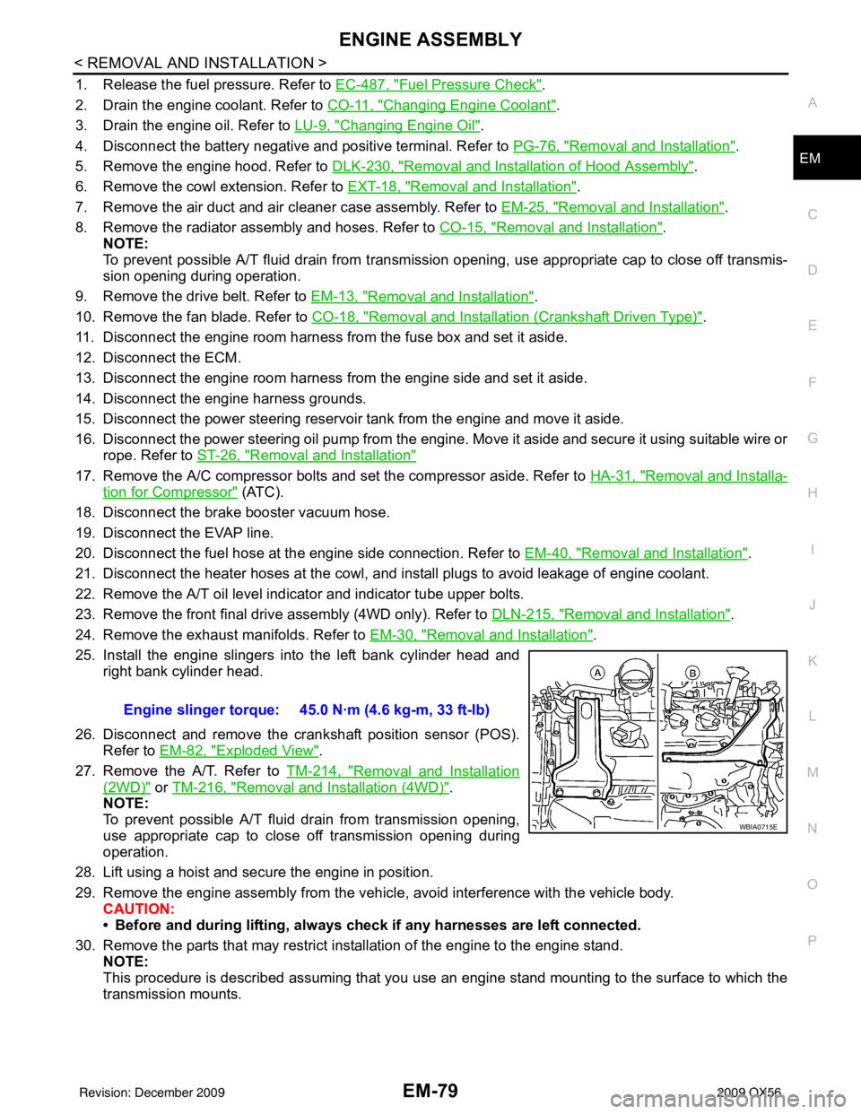
25. Install the engine slingers into the left bank cylinder head and right bank cylinder head.
26. Disconnect and remove the crankshaft position sensor (POS). Refer to EM-82, "
Exploded View".
27. Remove the A/T. Refer to TM-214, "
Removal and Installation
(2WD)" or TM-216, "Removal and Installation (4WD)".
NOTE:
To prevent possible A/T fluid drain from transmission opening,
use appropriate cap to close off transmission opening during
operation.
28. Lift using a hoist and secure the engine in position.
29. Remove the engine assembly from the vehicl e, avoid interference with the vehicle body.
CAUTION:
• Before and during lifting, always check if any harnesses are left connected.
30. Remove the parts that may restrict installation of the engine to the engine stand. NOTE:
This procedure is described assuming that you use an engine stand mounting to the surface to which the
transmission mounts. Engine slinger torque: 45.0 N·m (4.6 kg-m, 33 ft-lb)
WBIA0715E
Revision: December 20092009 QX56
Page 1904 of 4171
ENGINE ASSEMBLYEM-81
< REMOVAL AND INSTALLATION >
C
DE
F
G H
I
J
K L
M A
EM
NP
O
CAUTION:
• When replacing an engine or tr
ansmission you must make sure the dowels are installed correctly
during re-assembly.
• Improper alignment caused by missing dowels m ay cause vibration, oil leaks or breakage of driv-
etrain components.
INSPECTION AFTER INSTALLATION
• Before starting the engine, check oil/fluid levels including engine coolant and engine oil. If the levels are lower than required quantity, fill to the specified level. Refer to MA-12, "
Fluids and Lubricants".
• Use procedure below to check for fuel leakage.
• Turn ignition switch ON (with engine stopped). With fuel pressure applied to the fuel piping, check for fuel leakage at the connection points.
• Start engine. With engine speed increased, check again for fuel leakage at connection points.
• Run engine to check for unusual noise and vibration.
NOTE:
If hydraulic pressure inside timing chain tensioner drops after removal and installation, slack in the guide
may generate a pounding noise during and just after engine start. However, this is normal. Noise will stop
after hydraulic pressure rises.
• Warm up engine thoroughly to make sure there is no leakage of fuel, exhaust gas, or any oils/fluids including
engine oil and engine coolant.
• Bleed air from passages in lines and hoses, such as in cooling system.
• After cooling down the engine, again check oil/fluid levels including engine oil and engine coolant. Refill to specified level if necessary.
• Summary of the inspection items:
*Power steering fluid, brake fluid, etc. Item
Before starting engine Engine runningAfter engine stopped
Engine coolant LevelLeakage Level
Engine oil LevelLeakage Level
Transmission/transaxle/A/T flu-
id Leakage
Level/Leakage —
Other oils and fluids* LevelLeakage Level
Fuel LeakageLeakage Leakage
Exhaust gas —Leakage —
Revision: December 20092009 QX56
Page 2220 of 4171
GI-26
< PRECAUTION >
PRECAUTIONS
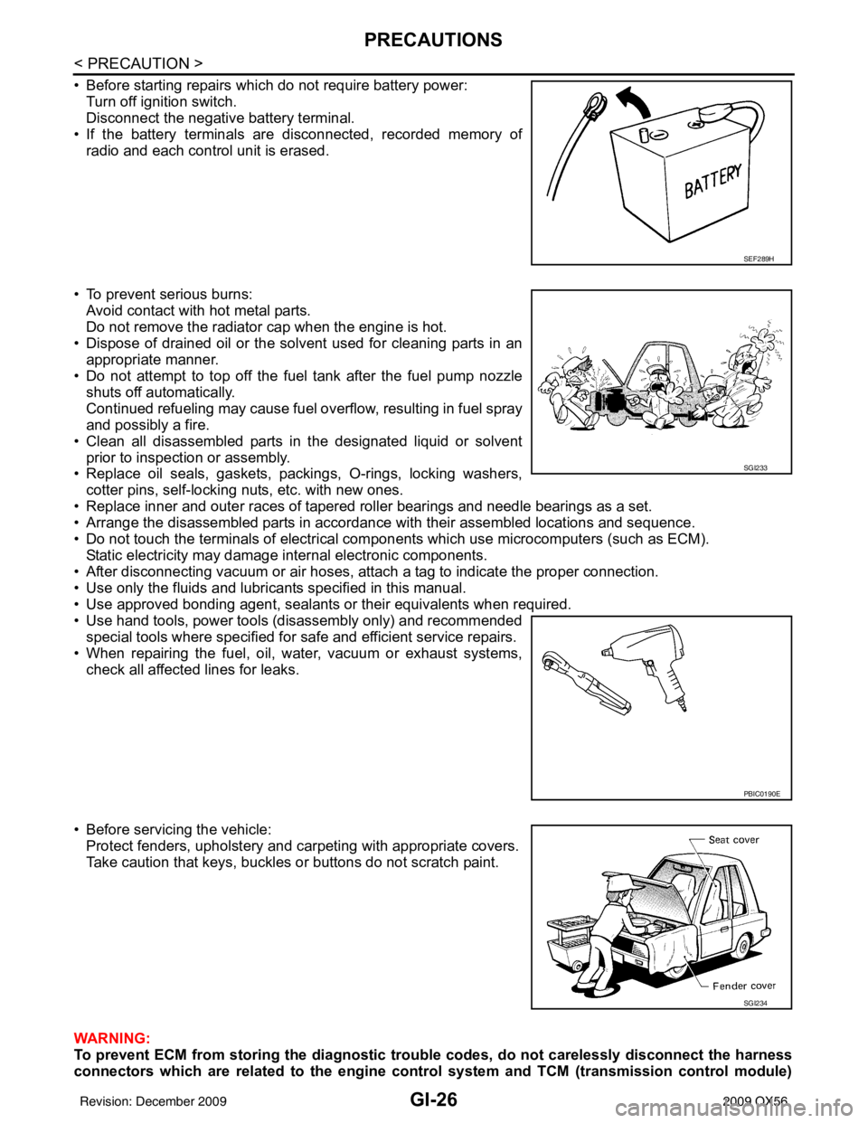
• Before starting repairs which do not require battery power:Turn off ignition switch.
Disconnect the negative battery terminal.
• If the battery terminals are disconnected, recorded memory of radio and each control unit is erased.
• To prevent serious burns: Avoid contact with hot metal parts.
Do not remove the radiator cap when the engine is hot.
• Dispose of drained oil or the solvent used for cleaning parts in an appropriate manner.
• Do not attempt to top off the fuel tank after the fuel pump nozzle
shuts off automatically.
Continued refueling may cause fuel overflow, resulting in fuel spray
and possibly a fire.
• Clean all disassembled parts in the designated liquid or solvent prior to inspection or assembly.
• Replace oil seals, gaskets, packings, O-rings, locking washers,
cotter pins, self-locking nuts, etc. with new ones.
• Replace inner and outer races of tapered roller bearings and needle bearings as a set.
• Arrange the disassembled parts in accordance with their assembled locations and sequence.
• Do not touch the terminals of electrical com ponents which use microcomputers (such as ECM).
Static electricity may damage internal electronic components.
• After disconnecting vacuum or air hoses, atta ch a tag to indicate the proper connection.
• Use only the fluids and lubricants specified in this manual.
• Use approved bonding agent, sealants or their equivalents when required.
• Use hand tools, power tools (disassembly only) and recommended special tools where specified for safe and efficient service repairs.
• When repairing the fuel, oil, water, vacuum or exhaust systems, check all affected lines for leaks.
• Before servicing the vehicle: Protect fenders, upholstery and carpeting with appropriate covers.
Take caution that keys, buckles or buttons do not scratch paint.
WARNING:
To prevent ECM from storing the diagnostic tro uble codes, do not carelessly disconnect the harness
connectors which are related to the engine control system and TCM (transmission control module)
SEF289H
SGI233
PBIC0190E
SGI234
Revision: December 20092009 QX56
Page 2696 of 4171

CHASSIS AND BODY MAINTENANCEMA-23
< ON-VEHICLE MAINTENANCE >
C
DE
F
G H
I
J
K L
M B
MA
N
O A
Checking the A/T Fluid (ATF)INFOID:0000000004215539
CAUTION:
If using the vehicle for towing, the A/T fluid must be replaced as specified. Refer to
MA-8, "
Introduc-
tion of Periodic Maintenance".
1. Before driving, the A/T fluid level can be checked at A/T fluid temperatures of 30 ° to 50 ° C (86 ° to 122° F) using the “COLD”
range on the A/T fluid level gauge as follows:
a. Park the vehicle on a level surface and set the parking brake.
b. Start the engine and move the A/T shift selector through each gear position. Shift the A/T shift selector into the “P” position.
c. Check the A/T fluid level with the engine idling.
d. Remove the A/T fluid level gauge and wipe it clean with a lint- free paper.
CAUTION:
When wiping the A/T fluid from the A/T fluid level gauge,
always use a lint-free paper, not a cloth.
e. Re-insert the A/T fluid level gauge into the A/T fluid charging pipe until the cap contacts the top of the A/T fluid charging pipe
as shown.
CAUTION:
To check A/T fluid level, insert th e A/T fluid level gauge until
the cap contacts the top of the A/T fluid charging pipe, with
the gauge reversed from the normal inserted position.
f. Remove the A/T fluid level gauge and note the A/T fluid level. If the A/T fluid level is at low side of range, add A/T fluid to the
transmission through the A/T fluid charging pipe.
CAUTION:
Do not overfill the tran smission with A/T fluid.
g. Install the A/T fluid level gauge and the A/T fluid level gauge bolt.
2. Warm up the engine and transmission.
3. Check for any A/T fluid leaks.
4. Drive the vehicle to increase the A/T fluid temperature to 80 ° C (176 ° F).
5. Allow the A/T fluid temperature to fall to approximately 65 °C (149° F). Use the CONSULT-III to monitor the
A/T fluid temperature as follows:
LLIA0071E
A/T fluid level
gauge bolt : Refer to
TM-214, "Removal and Installation (2WD)" or TM-216, "Removal
and Installation (4WD)"
SCIA2899E
SLIA0016E
Revision: December 20092009 QX56
Page 2697 of 4171

MA-24
< ON-VEHICLE MAINTENANCE >
CHASSIS AND BODY MAINTENANCE
NOTE:
The A/T fluid level will be significantly affected by the A/T fluid temperature as shown. Therefore monitor
the A/T fluid temperature data using the CONSULT-III.
a. Connect CONSULT-III to data link connector.
b. Select “MAIN SIGNALS” in “DATA MONI TOR” mode for “A/T” with CONSULT-III.
c. Read out the value of “ATF TEMP 1”.
6. Re-check the A/T fluid level at A/T fluid temperatures of approxi- mately 65 °C (149° F) using the “HOT” range on the A/T fluid
level gauge as shown. The HOT range is between 50 ° - 80 ° C
(122° - 176 ° F).
CAUTION:
• When wiping the A/T fluid from the A/T fluid level gauge,
always use lint-free paper, not a cloth.
• To check the A/T fluid level , insert the A/T fluid level
gauge until the cap contacts the top of the A/T fluid charg-
ing pipe, with the gauge reversed from the normal
inserted position as shown.
7. Check the A/T fluid condition. • If the A/T fluid is very dark or has some burned smell, theremay be an internal problem with the transmission. Refer to
TM-183, "
A/T Fluid Cooler Cleaning". Flush the transmission
cooling system after repairing the transmission.
• If the A/T fluid contains frictional material (clutches, bands, etc.), replace the radiator and flush the transmission cooler
lines using cleaning solvent and compressed air after repairing
the transmission.
8. Install the A/T fluid level gauge in the A/T fluid charging pipe.
9. Tighten the A/T fluid level gauge bolt to specification.
Changing the A/T Fluid (ATF)INFOID:0000000004215540
CAUTION:
If using the vehicle for towing, the A/T fl uid must be replaced as specified. Refer to MA-8, "
Introduc-
tion of Periodic Maintenance".
1. Drive the vehicle to warm up the A/T fluid to approximately 80 ° C (176 ° F).
2. Stop the engine.
3. Remove the A/T fluid level gauge.
4. Drain the A/T fluid from the drain plug hole, then install the drain plug with a new gasket. Refill the transmission with new A/T
fluid. Always refill with the same volume as the drained A/T fluid.
Use the A/T fluid level gauge to check the A/T fluid level as
shown. Add A/T fluid as necessary.
LLIA0071E
A/T fluid level
gauge bolt : Refer to
TM-214, "Removal and Installation (2WD)" or TM-216, "Removal
and Installation (4WD)"
SCIA2899E
Drain plug : Refer to TM-220, "Component".
LLIA0071E
Revision: December 20092009 QX56
Page 2698 of 4171
CHASSIS AND BODY MAINTENANCEMA-25
< ON-VEHICLE MAINTENANCE >
C
DE
F
G H
I
J
K L
M B
MA
N
O A
• To flush out the old A/T fluid from the transmission o
il coolers, pour new A/T fluid into the A/T fluid charg-
ing pipe with the engine idling and at the same time drain the old A/T fluid from the auxiliary transmis-
sion oil cooler hose return line.
• When the color of the A/T fluid coming out of the aux iliary transmission oil cooler hose return line is
about the same as the color of the new A/T fluid, flushing out the old A/T fluid is complete. The amount
of new A/T fluid used for flushing should be 30% to 50% increase of the specified capacity.
CAUTION:
• If Genuine NISSAN Matic S ATF is not available, Genuine NISSAN Matic J ATF may also be used.
• Using ATF fluid other than Genuine NISSAN Matic S ATF or Matic J ATF will cause deterioration
in driveability and A/T durability, and may damage the A/T, which is not covered by the warranty.
• When filling the transmission with A/T fluid, do not spill the A/T fluid on any heat generating
parts such as the exhaust parts.
• Do not reuse the drain plug gasket.
5. Install the A/T fluid level gauge and tighten t he A/T fluid level gauge bolt to specification.
6. Drive the vehicle to warm up the A/T fluid to approximately 80 ° C (176 ° F).
7. Check the fluid level and condition. If the A/T fluid is still dirty, repeat steps 2 through 6.
8. Install the A/T fluid level gauge in the A/T fluid charging pipe and install the A/T fluid level gauge bolt.
9. Tighten the A/T fluid level gauge bolt to specification.
Checking Transfer FluidINFOID:0000000004215545
CAUTION:
If using the vehicle for towing, the transfer fluid must be replaced as specified. Refer to MA-8, "
Intro-
duction of Periodic Maintenance".
FLUID LEAKAGE AND FLUID LEVEL
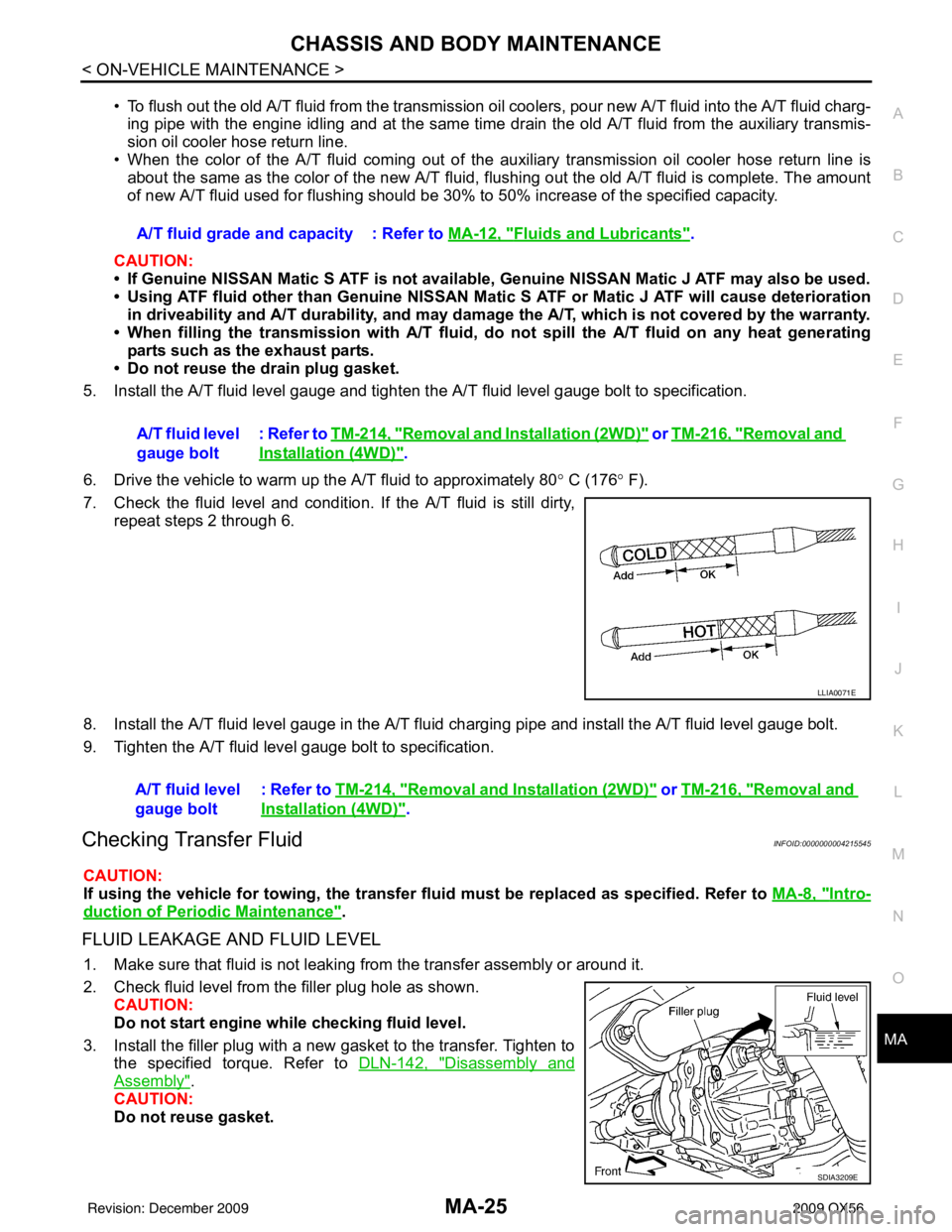
1. Make sure that fluid is not leaking from the transfer assembly or around it.
2. Check fluid level from the filler plug hole as shown.
CAUTION:
Do not start engine while checking fluid level.
3. Install the filler plug with a new gasket to the transfer. Tighten to the specified torque. Refer to DLN-142, "
Disassembly and
Assembly".
CAUTION:
Do not reuse gasket. A/T fluid grade and capacity : Refer to MA-12, "
Fluids and Lubricants".
A/T fluid level
gauge bolt : Refer to
TM-214, "
Removal and Installation (2WD)" or TM-216, "Removal and
Installation (4WD)".
LLIA0071E
A/T fluid level
gauge bolt : Refer to TM-214, "Removal and Installation (2WD)" or TM-216, "Removal and
Installation (4WD)".
SDIA3209E
Revision: December 20092009 QX56