height adjustment INFINITI QX56 2009 Factory Owner's Manual
[x] Cancel search | Manufacturer: INFINITI, Model Year: 2009, Model line: QX56, Model: INFINITI QX56 2009Pages: 4171, PDF Size: 84.65 MB
Page 3154 of 4171

RSU-6
< ON-VEHICLE MAINTENANCE >
REAR SUSPENSION ASSEMBLY
ON-VEHICLE MAINTENANCE
REAR SUSPENSION ASSEMBLY
On-Vehicle Inspection and ServiceINFOID:0000000003772290
Check all of the component mountings for any excessive looseness, or back lash. Check the components for
any excessive wear, damage, or abnormal conditions. Repair or replace the components as necessary.
SHOCK ABSORBER INSPECTION
Check the shock absorbers for any air l eaks or damage, and replace as necessary.
Check the hoses for any air leaks or damage, and replace as necessary.
Wheel AlignmentInspectionINFOID:0000000005889867
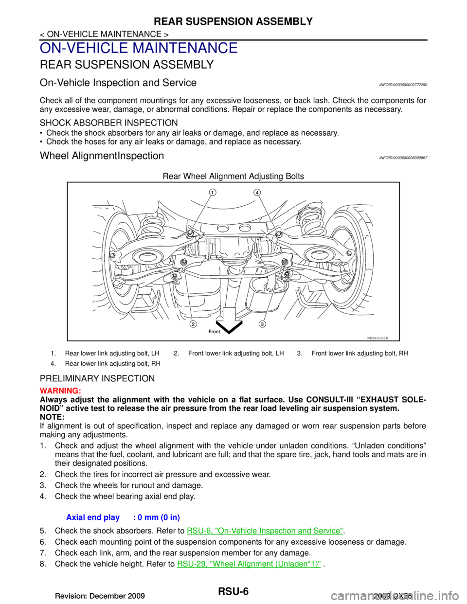
Rear Wheel Alignment Adjusting Bolts
PRELIMINARY INSPECTION
WARNING:
Always adjust the alignm ent with the vehicle on a flat su rface. Use CONSULT-III “EXHAUST SOLE-
NOID” active test to release the air pressure from the rear load leveling air suspension system.
NOTE:
If alignment is out of specificat ion, inspect and replace any damaged or worn rear suspension parts before
making any adjustments.
1. Check and adjust the wheel alignment with the vehicle under unladen conditions. “Unladen conditions”
means that the fuel, coolant, and lubricant are full; and that the spare tire, jack, hand tools and mats are in
their designated positions.
2. Check the tires for incorrect air pressure and excessive wear.
3. Check the wheels for runout and damage.
4. Check the wheel bearing axial end play.
5. Check the shock absorbers. Refer to RSU-6, "On-Vehicle Inspection and Service"
.
6. Check each mounting point of the suspension components for any excessive looseness or damage.
7. Check each link, arm, and the rear suspension member for any damage.
8. Check the vehicle height. Refer to RSU-29, "Wheel Alignment (Unladen
*1)" .
WEIA0102E
1. Rear lower link adjusting bolt, LH 2. Front lower link adjusting bolt, LH 3. Front lower link adjusting bolt, RH
4. Rear lower link adjusting bolt, RH
Axial end play : 0 mm (0 in)
Revision: December 20092009 QX56
Page 3163 of 4171

SHOCK ABSORBERRSU-15
< REMOVAL AND INSTALLATION >
C
DF
G H
I
J
K L
M A
B
RSU
N
O P
SHOCK ABSORBER
Removal and InstallationINFOID:0000000005889873
REMOVAL
1. Remove the wheel and tire assembly using power tool. Refer to WT-41, "Adjustment".
2. If equipped with the rear load leveling air suspens ion system, use CONSULT-III "EXHAUST SOLENOID"
active test to release the air pressure from the rear load leveling air suspension system.
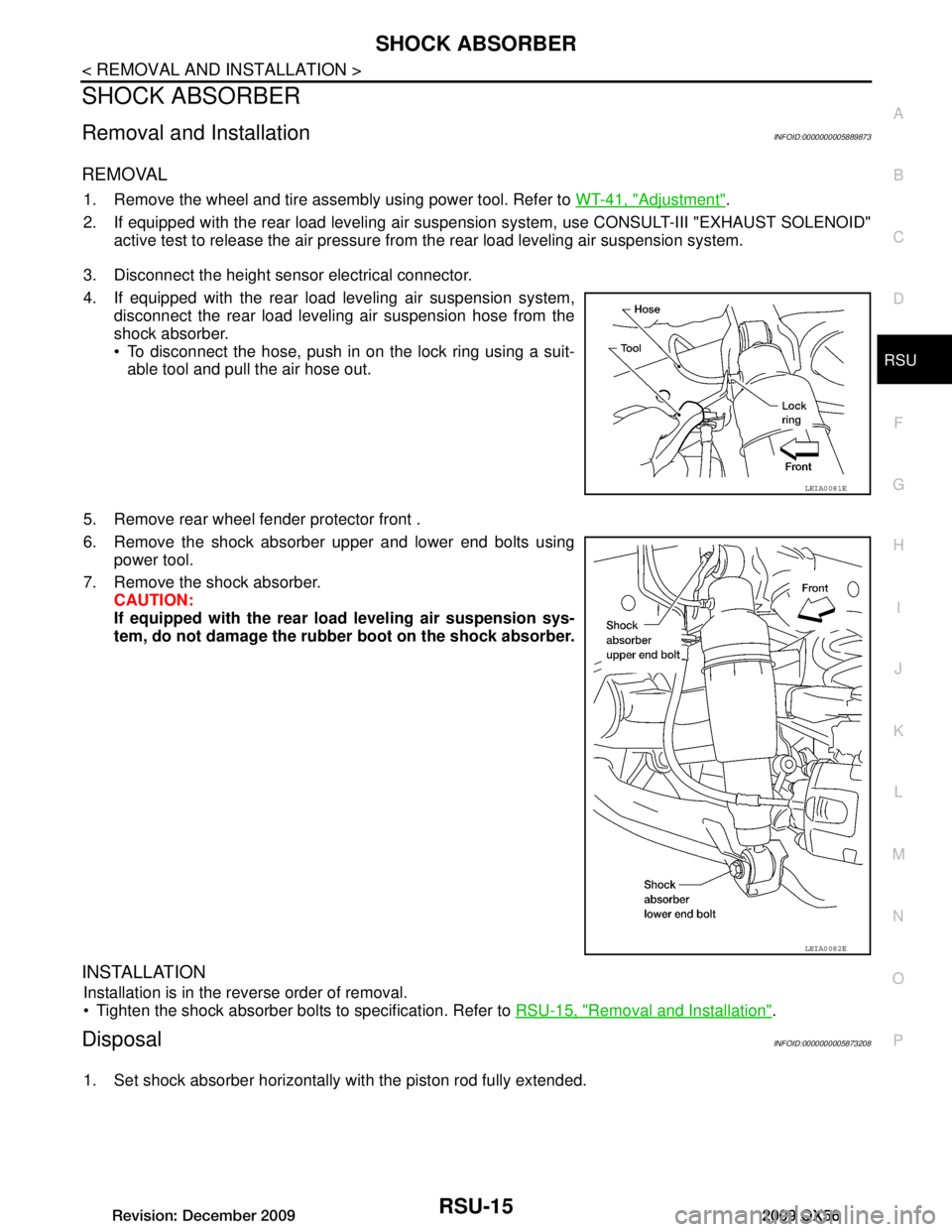
3. Disconnect the height sensor electrical connector.
4. If equipped with the rear load leveling air suspension system, disconnect the rear load leveling air suspension hose from the
shock absorber.
To disconnect the hose, push in on the lock ring using a suit-able tool and pull the air hose out.
5. Remove rear wheel fender protector front .
6. Remove the shock absorber upper and lower end bolts using power tool.
7. Remove the shock absorber. CAUTION:
If equipped with the rear lo ad leveling air suspension sys-
tem, do not damage the rubber boot on the shock absorber.
INSTALLATION
Installation is in the reverse order of removal.
Tighten the shock absorber bolts to specification. Refer to RSU-15, "Removal and Installation"
.
DisposalINFOID:0000000005873208
1. Set shock absorber horizontally with the piston rod fully extended.
LEIA0081E
LEIA0082E
Revision: December 20092009 QX56
Page 3169 of 4171

REAR LOWER LINK & COIL SPRINGRSU-21
< REMOVAL AND INSTALLATION >
C
DF
G H
I
J
K L
M A
B
RSU
N
O P
REAR LOWER LINK & COIL SPRING
Removal and InstallationINFOID:0000000005889876
REMOVAL
1. Remove the wheel and tire assembly using power tool. Refer to WT-41, "Adjustment".
2. If equipped with rear load leveling air suspension system, use CONSULT-III “EXHAUST SOLENOID”
active test to release the air pressure from the rear load leveling air suspension system.
3. If equipped with the rear load leveling air suspension system, for removing the LH rear lower link and coil spring, remove the
height sensor arm bracket bolt from the rear lower link.
4. Remove speed sensor harness and brackets from rear lower link.
5. Set a suitable jack to relieve the coil spring tension and support the rear lower link.
6. Loosen the rear lower link adjusting bolt and nut connected to the rear suspension member, using power tool.
7. Remove the rear lower link bolt and nut from the knuckle using power tool.
LEIA0080E
LEIA0077E
LEIA0009E
LEIA0077E
Revision: December 20092009 QX56
Page 3200 of 4171

DIAGNOSIS SYSTEM (SUSPENSION CONTROL UNIT)
SCS-7
< FUNCTION DIAGNOSIS >
C
D F
G H
I
J
K L
M A
B
SCS
N
O P
DIAGNOSIS SYSTEM (SUS PENSION CONTROL UNIT)
CONSULT-III FunctionINFOID:0000000003772311
CONSULT-III can display each diagnostic item using the diagnostic test modes shown following.
WORK SUPPORT
Display Item List
DATA MONITOR
Display Item List
ACTIVE TEST
CAUTION:
Do not perform active test while driving.
Display Item List
AIR LEVELIZER diagnosis mode Description
WORK SUPPORT Supports inspection and adjustment. Commands are transmitted to the suspension control
unit for setting the status suitable for required operation, input/output signals are received
from the suspension control unit and received data is displayed.
SELF-DIAG RESULTS Displays suspension control unit self-diagnosis results.
DATA MONITOR Displays suspension control unit input/output data in real time.
ACTIVE TEST Operation of electrical loads can be checked by sending drive signal to them.
ECU PART NUMBER The part number of suspension control unit can be checked.
ItemDescription Condition
STANDARD HEIGHT LEVEL Resets the vehicle height to the initialization flag
setting stored in the suspension control unit. Vehicle unladen, set in a horizontal position and
not moving.
NOTE:
Do not take your eyes off the vehicle while CON-
SULT-III is processing.
ADJUST HEIGHT INI Sets the height initialization flag in the suspen-
sion control unit when the control unit has been
replaced or when the initialization flag has been
cleared using the "CLEAR HEIGHT INI" proce-
dure. Vehicle unladen, move vehicle forward and back-
ward approx. 5 m (16.4 ft) and rock vehicle side
to side.
NOTE:
Do not move vehicle wh
ile CONSULT-III is pro-
cessing.
CLEAR HEIGHT INI Clears the initialization flag in the suspension
control unit. Vehicle unladen.
Display item [unit] ALL
SIGNALS SELECTION FROM MENU
HEIGT SEN [V] XX
HEIGT CALC [mm] XX
SEN FIX TIME [HR] XX
HEIGT INI VAL [V] XX
COMPRESSOR [ON/OFF] XX
EXH SOLENOID [ON/OFF] XX
ACG L [ON/OFF] XX
Test Item Description
COMPRESSOR ON/OFF
Revision: December 20092009 QX56