length INFINITI QX56 2009 Factory Owner's Manual
[x] Cancel search | Manufacturer: INFINITI, Model Year: 2009, Model line: QX56, Model: INFINITI QX56 2009Pages: 4171, PDF Size: 84.65 MB
Page 2152 of 4171

DRIVE SHAFTFAX-15
< DISASSEMBLY AND ASSEMBLY >
CEF
G H
I
J
K L
M A
B
FA X
N
O P
4. Attach the circlip to the drive shaftm making sure circlip fits securely into groove on drive shaft. Then install drive shaft nut to
end of joint sub-assembly, and press-fit the circlip using a suit-
able tool as shown.
NOTE:
Discard the old circlip and use a new one for assembly.
5. Insert the specified quantit y of Genuine NISSAN Grease or
equivalent, into the joint sub-assembly and the large end of the
boot. Refer to MA-12, "Fluids and Lubricants"
.
6. Install the boot securely into the grooves (indicated by the * marks) as shown.
CAUTION:
If there is grease on the bo ot mounting surfaces (indicated
by the * marks) of the drive shaft and joint sub-assembly,
the boot may come off. Remove all grease from the drive
shaft surfaces.
7. Check that the boot installation length (L) is the specified length. Insert a suitable tool into the large end of the boot, as shown.
Bleed the air from the boot to prevent boot deformation.
CAUTION:
The boot may break if the boot installation length is less than the specified length.
Do not contact inside surface of boot with the tip of the suitable tool.
8. Secure large and small ends of the boot using new boot bands using tool as shown.
NOTE:
Discard the old boot bands and use new ones for assembly.
Secure boot band so that dimension (M) meets specificationas shown.
9. After installing the housing to the shaft, rotate the boot to check that it is positioned correctly. If the boot is
not positioned correctly, remove the old boot bands then reposition the boot and secure the boot with new
boot bands. Grease capacity : 145
− 165 g (5.11 − 5.82 oz)
RAC0049D
Boot installation length (L) : 168.4 mm (6.63 in)
Tool number : KV40107300 ( — )
WDIA0288E
RAC1133D
Dimension (M) : 1.0 – 4.0 mm (0.039 – 0.157 in)
DSF0047D
Revision: December 20092009 QX56
Page 2153 of 4171
FAX-16
< SERVICE DATA AND SPECIFICATIONS (SDS)
SERVICE DATA AND SPECIFICATIONS (SDS)
SERVICE DATA AND SPECIFICATIONS (SDS)
SERVICE DATA AND SPECIFICATIONS (SDS)
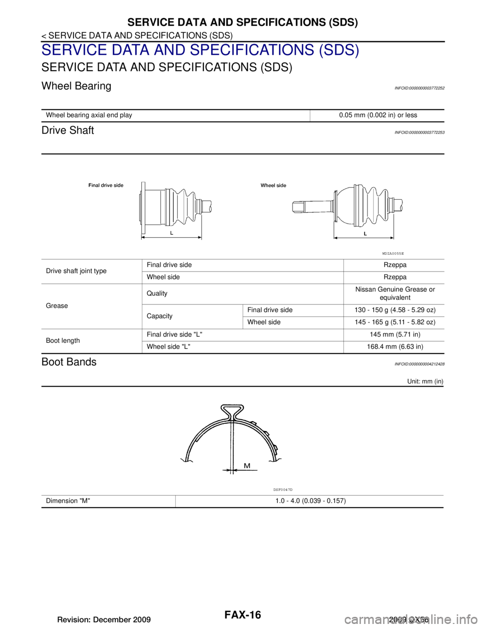
Wheel BearingINFOID:0000000003772252
Drive ShaftINFOID:0000000003772253
Boot BandsINFOID:0000000004212428
Unit: mm (in)
Wheel bearing axial end play 0.05 mm (0.002 in) or less
Drive shaft joint typeFinal drive side Rzeppa
Wheel side Rzeppa
Grease Quality
Nissan Genuine Grease or
equivalent
Capacity Final drive side 130 - 150 g (4.58 - 5.29 oz)
Wheel side 145 - 165 g (5.11 - 5.82 oz)
Boot length Final drive side "L" 145 mm (5.71 in)
Wheel side "L" 168.4 mm (6.63 in)
WDIA0055E
Dimension "M" 1.0 - 4.0 (0.039 - 0.157)
DSF0047D
Revision: December 20092009 QX56
Page 2178 of 4171
FSU-8
< ON-VEHICLE MAINTENANCE >
ON-VEHICLE SERVICE
• Always perform the following procedure on a flat surface.
• Make sure that no person is in front of the vehicle before pushing it.
1. Bounce the front of vehicle up and down to stabilize the vehicle height (posture).
2. Push the vehicle straight ahead about 5 m (16 ft).
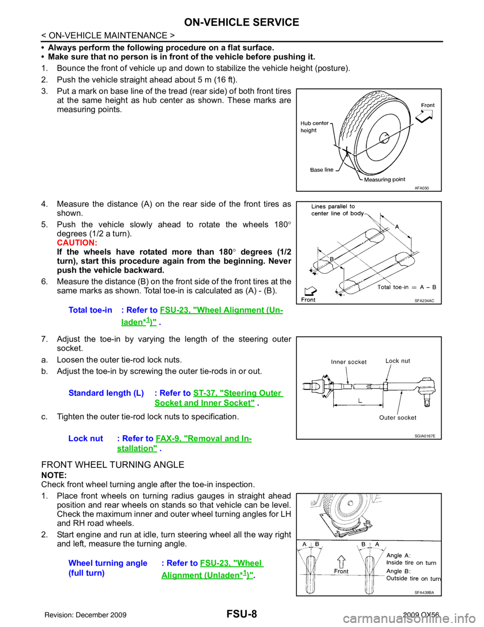
3. Put a mark on base line of the tread (rear side) of both front tires at the same height as hub center as shown. These marks are
measuring points.
4. Measure the distance (A) on the rear side of the front tires as shown.
5. Push the vehicle slowly ahead to rotate the wheels 180 °
degrees (1/2 a turn).
CAUTION:
If the wheels have rotated more than 180 ° degrees (1/2
turn), start this procedure again from the beginning. Never
push the vehicle backward.
6. Measure the distance (B) on the front side of the front tires at the
same marks as shown. Total toe- in is calculated as (A) - (B).
7. Adjust the toe-in by varying the length of the steering outer socket.
a. Loosen the outer tie-rod lock nuts.
b. Adjust the toe-in by screwing the outer tie-rods in or out.
c. Tighten the outer tie-rod lock nuts to specification.
FRONT WHEEL TURNING ANGLE
NOTE:
Check front wheel turning angle after the toe-in inspection.
1. Place front wheels on turning radius gauges in straight ahead position and rear wheels on stands so that vehicle can be level.
Check the maximum inner and outer wheel turning angles for LH
and RH road wheels.
2. Start engine and run at idle, turn steering wheel all the way right and left, measure the turning angle.
AFA050
Total toe-in : Refer to FSU-23, "Wheel Alignment (Un-
laden*1)" .
SFA234AC
Standard length (L) : Refer to ST-37, "Steering Outer
Socket and Inner Socket" .
Lock nut : Refer to FA X - 9 , "
Removal and In-
stallation" .
SGIA0167E
Wheel turning angle
(full turn) : Refer to
FSU-23, "Wheel
Alignment (Unladen*1)".
SFA439BA
Revision: December 20092009 QX56
Page 2217 of 4171

IDENTIFICATION INFORMATIONGI-23
< FEATURES OF NEW MODEL >
C
DE
F
G H
I
J
K L
M B
GI
N
O P
DimensionsINFOID:0000000003771193
Unit: mm (in)
Wheels & TiresINFOID:0000000003771194
* With Steel Wheel Drive type
2WD4WD
Overall length 5254 (206.9)5255 (206.9)
Overall width 2001 (78.8)2001 (78.8)
Overall height (with roof rack) 1976.8 (77.8)1997.7 (78.7)
Front tread width 1715 (67.5)1715 (67.5)
Rear tread width 1715 (67.5)1715 (67.5)
Wheelbase 3130 (123.2)3130 (123.2)
Minimum Running Ground Clearance (at front suspension) 211.2 (8.3)232 (9.1)
Drive Type Grade Road wheelTireSpare tire size*
All QX56 20x8JJ Chromium Aluminum Alloy P275/60R20P275/60R20
Revision: December 20092009 QX56
Page 2222 of 4171

GI-28
< PRECAUTION >
PRECAUTIONS
• To reinstall the rubber hose securely, make sure that hose insertionlength and orientation is correct. (If tube is equipped with hose
stopper, insert rubber hose into tube until it butts up against hose
stopper.)
HOSE CLAMPING
• If old rubber hose is re-used, install hose clamp in its original posi-tion (at the indentation where the old clamp was). If there is a trace
of tube bulging left on the old rubber hose, align rubber hose at
that position.
• Discard old clamps; replace with new ones.
• After installing plate clamps, apply force to them in the direction of the arrow, tightening rubber hose equally all around.
Engine OilsINFOID:0000000003771204
Prolonged and repeated contact with used engine oil may cause skin cancer. Try to avoid direct skin contact
with used oil.
If skin contact is made, wash thoroughly with soap or hand cleaner as soon as possible.
HEALTH PROTECTION PRECAUTIONS
• Avoid prolonged and repeated contact with oils, particularly used engine oils.
• Wear protective clothing, including impervious gloves where practicable.
• Do not put oily rags in pockets.
• Avoid contaminating clothes, pa rticularly underpants, with oil.
• Heavily soiled clothing and oil-impregnated footwear should not be worn. Overalls must be cleaned regu- larly.
• First aid treatment should be obtained immediately for open cuts and wounds.
• Use barrier creams, applying them before each work period, to help the removal of oil from the skin.
• Wash with soap and water to ensure all oil is removed (skin cleansers and nail brushes will help). Prepara-
tions containing lanolin replace the natural skin oils which have been removed.
• Do not use gasoline, kerosene, diesel fuel, gas oil, thinners or solvents for cleaning skin.
• If skin disorders develop, obtain medical advice without delay.
• Where practical, degrease components prior to handling.
• Where there is a risk of eye contact, eye protection should be worn, for example, chemical goggles or face
shields; in addition an eye wash facility should be provided.
ENVIRONMENTAL PROTECTION PRECAUTIONS
SMA020D
SMA021D
SMA022D
Revision: December 20092009 QX56
Page 3089 of 4171
RAX-14
< DISASSEMBLY AND ASSEMBLY >
REAR DRIVE SHAFT
7. After installation, pull on the shaft to check engagement between the joint sub-assembly and the stopper
ring.
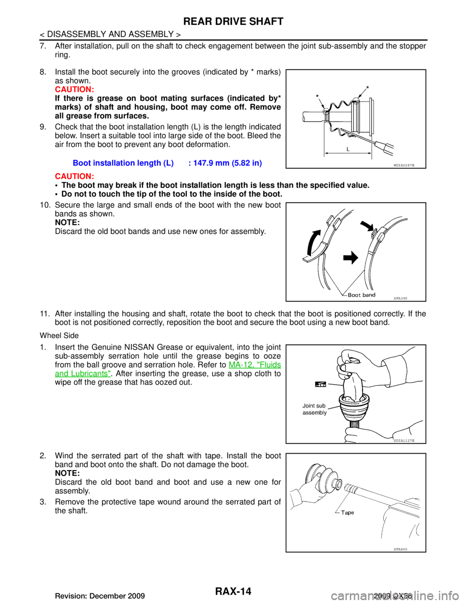
8. Install the boot securely into the grooves (indicated by * marks) as shown.
CAUTION:
If there is grease on boot mating surfaces (indicated by*
marks) of shaft and housing, boot may come off. Remove
all grease from surfaces.
9. Check that the boot installation length (L) is the length indicated below. Insert a suitable tool into large side of the boot. Bleed the
air from the boot to pr event any boot deformation.
CAUTION:
The boot may break if the boot installation length is less than the specified value.
Do not to touch the tip of the t ool to the inside of the boot.
10. Secure the large and small ends of the boot with the new boot bands as shown.
NOTE:
Discard the old boot bands and use new ones for assembly.
11. After installing the housing and shaft, rotate the boot to check that the boot is positioned correctly. If the
boot is not positioned correctly, reposition the boot and secure the boot using a new boot band.
Wheel Side
1. Insert the Genuine NISSAN Grease or equivalent, into the joint
sub-assembly serration hole until the grease begins to ooze
from the ball groove and serration hole. Refer to MA-12, "Fluids
and Lubricants". After inserting the grease, use a shop cloth to
wipe off the grease that has oozed out.
2. Wind the serrated part of the shaft with tape. Install the boot
band and boot onto the shaft. Do not damage the boot.
NOTE:
Discard the old boot band and boot and use a new one for
assembly.
3. Remove the protective tape wound around the serrated part of the shaft. Boot installation length
(L) : 147.9 mm (5.82 in)
WDIA0287E
SFA395
SDIA1127E
SFA800
Revision: December 20092009 QX56
Page 3090 of 4171
REAR DRIVE SHAFTRAX-15
< DISASSEMBLY AND ASSEMBLY >
CEF
G H
I
J
K L
M A
B
RAX
N
O P
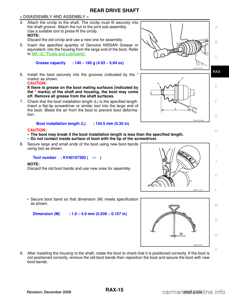
4. Attach the circlip to the shaft. The circlip must fit securely into
the shaft groove. Attach the nut to the joint sub-assembly.
Use a suitable tool to press-fit the circlip.
NOTE:
Discard the old circlip and use a new one for assembly.
5. Insert the specified quantit y of Genuine NISSAN Grease or
equivalent, into the housing from the large end of the boot. Refer
to MA-12, "Fluids and Lubricants"
.
6. Install the boot securely into the grooves (indicated by the * marks) as shown.
CAUTION:
If there is grease on the boot mating surfaces (indicated by
the * marks) of the shaft and housing, the boot may come
off. Remove all grease from the shaft surfaces.
7. Check that the boot installation length (L) is the specified length. Insert a flat-tip screwdriver or similar tool into the large end of
the boot. Bleed the air from the boot to prevent boot deforma-
tion.
CAUTION:
The boot may break if the boot installation length is less than the specified length.
Do not contact inside surface of boot with the tip of the screwdriver.
8. Secure large and small ends of the boot using new boot bands using tool as shown.
NOTE:
Discard the old boot bands and use new ones for assembly.
Secure boot band so that dimension (M) meets specificationas shown.
9. After installing the housing to the shaft, rotate the boot to check that it is positioned correctly. If the boot is
not positioned correctly, remove the old boot bands then reposition the boot and secure the boot with new
boot bands. Grease capacity : 140
− 160 g (4.93 − 5.64 oz)
RAC0049D
Boot installation length (L) : 134.5 mm (5.30 in)
Tool number : KV40107300 ( — )
WDIA0288E
RAC1133D
Dimension (M) : 1.0 – 4.0 mm (0.039 – 0.157 in)
DSF0047D
Revision: December 20092009 QX56
Page 3091 of 4171
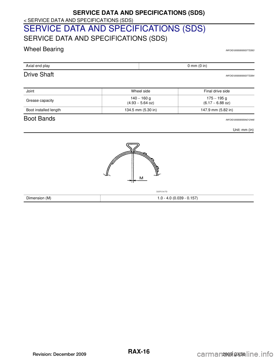
RAX-16
< SERVICE DATA AND SPECIFICATIONS (SDS)
SERVICE DATA AND SPECIFICATIONS (SDS)
SERVICE DATA AND SPECIFICATIONS (SDS)
SERVICE DATA AND SPECIFICATIONS (SDS)
Wheel BearingINFOID:0000000003772263
Drive ShaftINFOID:0000000003772264
Boot BandsINFOID:0000000004212446
Unit: mm (in)
Axial end play0 mm (0 in)
Joint Wheel side Final drive side
Grease capacity140
− 160 g
(4.93 − 5.64 oz) 175
− 195 g
(6.17 − 6.88 oz)
Boot installed length 134.5 mm (5.30 in) 147.9 mm (5.82 in)
Dimension (M) 1.0 - 4.0 (0.039 - 0.157)
DSF0047D
Revision: December 20092009 QX56
Page 3190 of 4171

SB-12
< ON-VEHICLE REPAIR >
SEAT BELTS
4. Check the shoulder seat belt guide and shoulder belt height adjuster for\
front seats. Ensure guide swivelsfreely and that belt lays flat and does not bind in guide. Ensure height adjuster operates properly and
holds securely.
5. Check retractor operation:
a. Fully extend the seat belt webbing and check for twists, tears or other damage.
b. Allow the seat belt to retract. Ensure that belt retu rns smoothly and completely into the retractor. If the
seat belt does not return smoothly, wipe the inside of the loops with a clean paper cloth, because dirt built
up in the loops of the upper anchors can c ause the seat belts to retract slowly.
c. Fasten the seat belt. Check the seat belt returns smoothly and completely to the retractor. If the belt does not return smoothly, the cause may be an accumulati on of dust or dirt. Use the “SEAT BELT TAPE SET”
and perform the following steps.
Inspect the front seat belt through-anchor:1. Pull the seat belt out to a length of 500 mm (19.69 in) or more.
2. Use a clip or other device to hold the seat belt at the center pillar belt opening.
3. Pass a thin wire through the through-anchor belt opening. Hold both ends of the wire and pull taut while moving it up and down several times along the belt opening surface to remove dirt.
4. Any dirt that cannot be removed with the wir e can be removed by cleaning the opening with a clean
cloth.
5. Apply tape at the point where the belt contacts the through-anchor belt opening.
NOTE:
Apply the tape so that there is no looseness or wrinkling.
6. Remove the clip holding the seat belt and check that the belt returns smoothly.
7. Repeat steps above as necessary to check the other seat belts.
SEAT BELT RETRACTOR ON-VEHICLE CHECK
Emergency Locking Retractors (ELR) and Automatic Locking Retractors (ALR)
NOTE:
All seat belt retractors are of the Emergency Locking Retractors (ELR) type. In an emergency (sudden stop)
the retractor will lock and prevent the belt from ext ending any further. All 3-point type seat belt retractors
except the driver's seat belt also have an Automati c Locking Retractors (ALR) mode. The ALR mode (also
called child restraint mode) is used when installing child seats. The ALR mode is activated when the seat belt
is fully extended. When the belt is then retracted partiall y, the ALR mode automatically locks the seat belt in a
specific position so the belt cannot be extended any furt her. To cancel the ALR mode, allow the seat belt to
fully wind back into the retractor.
Check the seat belt retractors using the following test(s ) to determine if a seat belt retractor and belt assembly
is operating properly.
ELR Function Stationary Check
Grasp the shoulder belt and pull forward quickly. The re tractor should lock and prevent the belt from extending
further.
ALR Function Stationary Check
1. Pull out entire length of seat belt from retractor until a click is heard.
2. Retract the belt partially. A clicking noise should be hear d as the belt retracts indicating that the retractor is
in the Automatic Locking Retractor (ALR) mode.
3. Grasp the seat belt and try to pull out the retractor. The belt must lock and not extend any further. If neces-
sary replace the seat belt retractor and belt assembly.
4. Allow the entire length of the belt to re tract to cancel the automatic locking mode.
ELR Function Moving Check
WARNING:
Perform the following test in a safe, open area clear of other vehicles and obstructions (for example, a
large, empty parking lot). Road surface must be p aved and dry. DO NOT perform the following test on
wet or gravel roads or on public streets and highw ays. This could result in an accident and serious
personal injury. The driver and passenger must be prepared to brace themselves in the event the
retractor does not lock.
1. Fasten drivers seat belt. Buckle a passenger in to the seat for the belt that is to be tested.
Revision: December 20092009 QX56
Page 3612 of 4171

STEERING COLUMNST-21
< REMOVAL AND INSTALLATION >
C
DE
F
H I
J
K L
M A
B
ST
N
O P
4. Remove lock nut and bolt, then separate upper shaft from upper joint.
5. Remove two nuts and two bolts, then remove steering column assembly from steering member.
6. Remove hole cover seal and clamp.
7. Remove mounting nuts, then remove hole cover from dash panel.
8. Raise vehicle, then remove mounting bolt (lower side) of lower joint shaft and remove lower joint shaft and upper shaft as an
assembly.
INSPECTION AFTER REMOVAL
Check for damage to steering column jacket tube. If damage is found, replace steering column with new
one.
If vehicle has been in a collision, check column length (L), (L
1) and L2) as shown. If out of specification,
replace steering column with new one.
LGIA0027E
LGIA0028E
LGIA0029E
Steering column length
L : Refer to ST-36, "Steering
Wheel"
L1: Refer to ST-36, "Steering
Wheel"
L2: Refer to ST-36, "Steering
Wheel"
WGIA0080E
Revision: December 20092009 QX56