length INFINITI QX56 2009 Factory Service Manual
[x] Cancel search | Manufacturer: INFINITI, Model Year: 2009, Model line: QX56, Model: INFINITI QX56 2009Pages: 4171, PDF Size: 84.65 MB
Page 7 of 4171

QUICK REFERNCE CHART: QX56
2010
*2: Verify the vehicle height. If vehicle height is not within ± 10 mm (0.39 in) of the specification, perform the control unit initialization pro-
cedure.
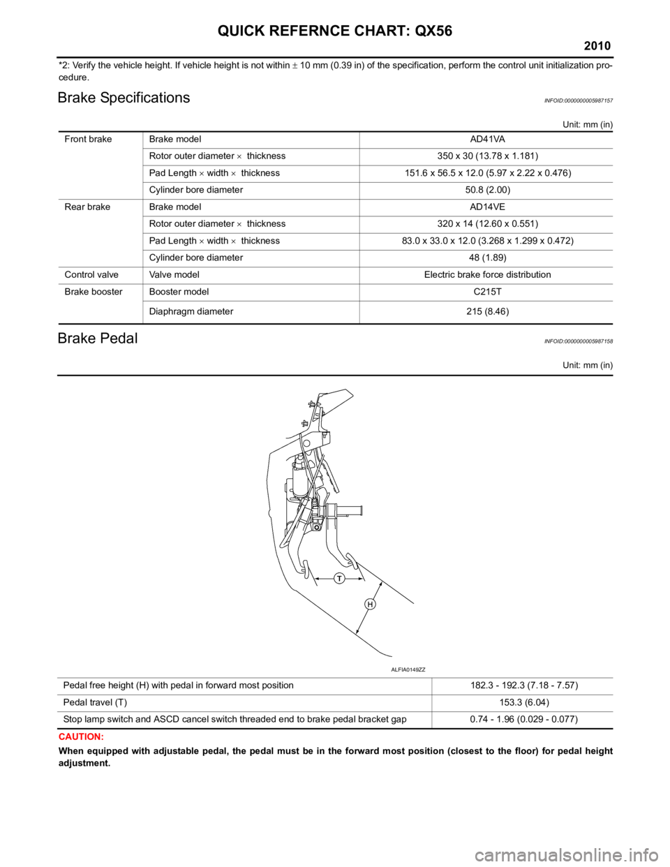
Brake SpecificationsINFOID:0000000005987157
Unit: mm (in)
Brake PedalINFOID:0000000005987158
Unit: mm (in)
CAUTION:
When equipped with adjustable pedal, the pedal must be in th e forward most position (closest to the floor) for pedal height
adjustment. Front brake Brake model AD41VA
Rotor outer diameter × thickness 350 x 30 (13.78 x 1.181)
Pad Length × width × thickness 151.6 x 56.5 x 12.0 (5.97 x 2.22 x 0.476)
Cylinder bore diameter 50.8 (2.00)
Rear brake Brake model AD14VE Rotor outer diameter × thickness 320 x 14 (12.60 x 0.551)
Pad Length × width × thickness 83.0 x 33.0 x 12.0 (3.268 x 1.299 x 0.472)
Cylinder bore diameter 48 (1.89)
Control valve Valve model Electric brake force distribution
Brake booster Booster model C215T
Diaphragm diameter 215 (8.46)
Pedal free height (H) with pedal in forward most position 182.3 - 192.3 (7.18 - 7.57)
Pedal travel (T) 153.3 (6.04)
Stop lamp switch and ASCD cancel switch threaded end to brake pedal bracket gap 0.74 - 1.96 (0.029 - 0.077)
ALFIA0149ZZ
Page 456 of 4171

BR-26
< ON-VEHICLE REPAIR >
BRAKE BOOSTER
BRAKE BOOSTER
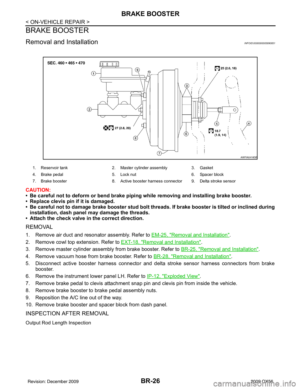
Removal and InstallationINFOID:0000000005890851
CAUTION:
• Be careful not to deform or bend brake piping while removing and installing brake booster.
• Replace clevis pin if it is damaged.
• Be careful not to damage brake booster stud bolt threads. If brake booster is tilted or inclined during
installation, dash panel may damage the threads.
• Attach the check valve in the correct direction.
REMOVAL
1. Remove air duct and resonator assembly. Refer to EM-25, "Removal and Installation".
2. Remove cowl top extension. Refer to EXT-18, "
Removal and Installation".
3. Remove master cylinder assembly from brake booster. Refer to BR-25, "
Removal and Installation".
4. Remove vacuum hose from brake booster. Refer to BR-28, "
Removal and Installation".
5. Disconnect active booster harness connector and delta stroke sensor harness connectors from brake booster.
6. Remove the instrument lower panel LH. Refer to IP-12, "
Exploded View".
7. Remove brake pedal to clevis attachment snap pin and clevis pin from inside the vehicle.
8. Remove brake booster to brake pedal assembly nuts.
9. Reposition the A/C line out of the way.
10. Remove brake booster and spacer block from dash panel.
INSPECTION AFTER REMOVAL
Output Rod Length Inspection
1. Reservoir tank 2. Master cylinder assembly3. Gasket
4. Brake pedal 5. Lock nut 6. Spacer block
7. Brake booster 8. Active booster harness connector 9. Delta stroke sensor
AWFIA0416GB
Revision: December 20092009 QX56
Page 457 of 4171

BRAKE BOOSTERBR-27
< ON-VEHICLE REPAIR >
C
DE
G H
I
J
K L
M A
B
BR
N
O P
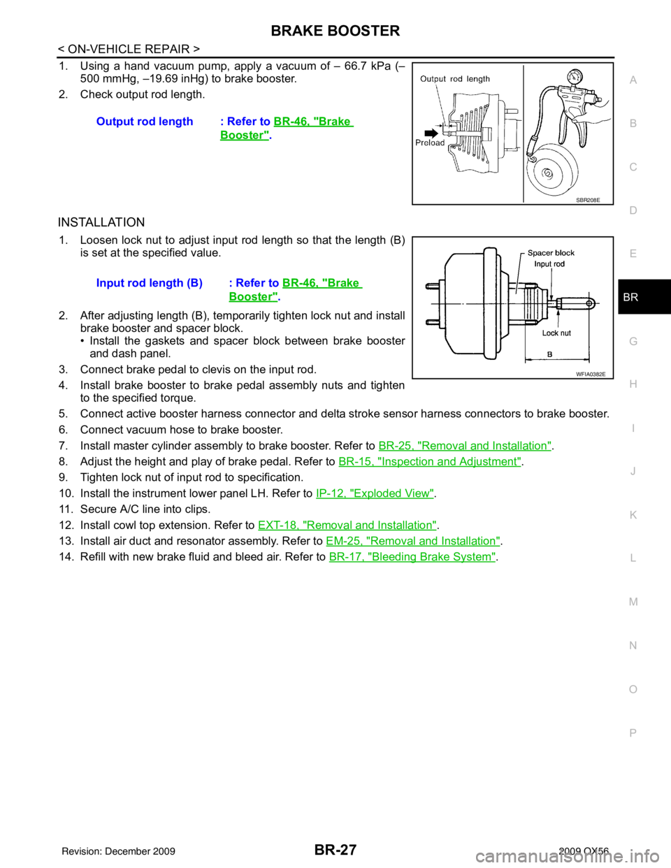
1. Using a hand vacuum pump, apply a vacuum of – 66.7 kPa (– 500 mmHg, –19.69 inHg) to brake booster.
2. Check output rod length.
INSTALLATION
1. Loosen lock nut to adjust input r od length so that the length (B)
is set at the specified value.
2. After adjusting length (B), temporarily tighten lock nut and install brake booster and spacer block.
• Install the gaskets and spacer block between brake boosterand dash panel.
3. Connect brake pedal to clevis on the input rod.
4. Install brake booster to brake pedal assembly nuts and tighten to the specified torque.
5. Connect active booster harness connector and delta st roke sensor harness connectors to brake booster.
6. Connect vacuum hose to brake booster.
7. Install master cylinder assembly to brake booster. Refer to BR-25, "
Removal and Installation".
8. Adjust the height and play of brake pedal. Refer to BR-15, "
Inspection and Adjustment".
9. Tighten lock nut of input rod to specification.
10. Install the instrument lower panel LH. Refer to IP-12, "
Exploded View".
11. Secure A/C line into clips.
12. Install cowl top extension. Refer to EXT-18, "
Removal and Installation".
13. Install air duct and resonator assembly. Refer to EM-25, "
Removal and Installation".
14. Refill with new brake fluid and bleed air. Refer to BR-17, "
Bleeding Brake System".
Output rod length : Refer to
BR-46, "
Brake
Booster".
SBR208E
Input rod length (B) : Refer to BR-46, "Brake
Booster".
WFIA0382E
Revision: December 20092009 QX56
Page 475 of 4171

SERVICE DATA AND SPECIFICATIONS (SDS)BR-45
< SERVICE DATA AND SPECIFICATIONS (SDS)
C
DE
G H
I
J
K L
M A
B
BR
N
O P
SERVICE DATA AND SPECIFICATIONS (SDS)
SERVICE DATA AND SPECIFICATIONS (SDS)
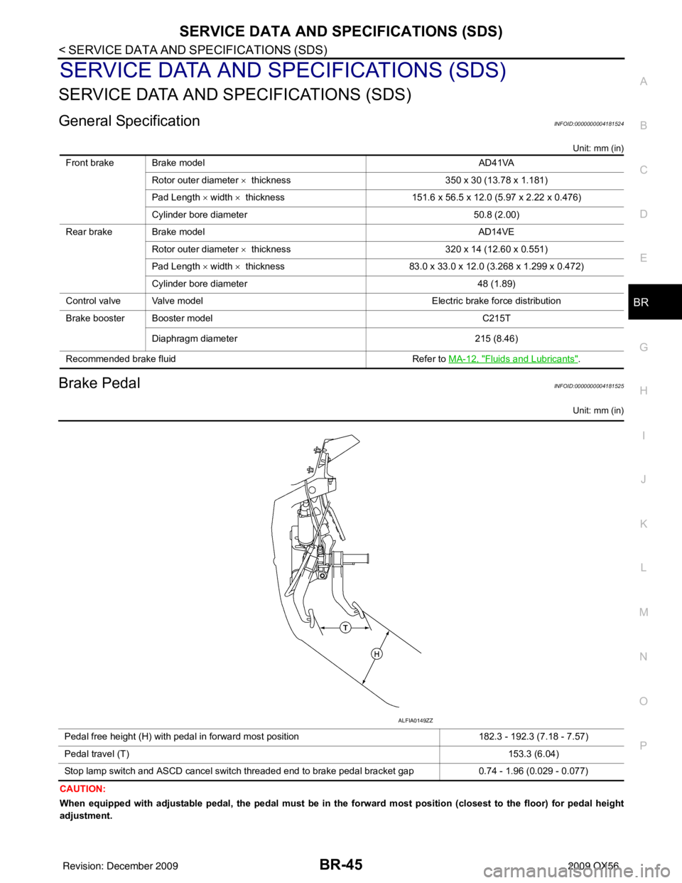
General SpecificationINFOID:0000000004181524
Unit: mm (in)
Brake PedalINFOID:0000000004181525
Unit: mm (in)
CAUTION:
When equipped with adjustable pedal, the pedal must be in the forward most position (closest to the floor) for pedal height
adjustment. Front brake Brake model
AD41VA
Rotor outer diameter × thickness 350 x 30 (13.78 x 1.181)
Pad Length × width × thickness 151.6 x 56.5 x 12.0 (5.97 x 2.22 x 0.476)
Cylinder bore diameter 50.8 (2.00)
Rear brake Brake model AD14VE
Rotor outer diameter × thickness 320 x 14 (12.60 x 0.551)
Pad Length × width × thickness 83.0 x 33.0 x 12.0 (3.268 x 1.299 x 0.472)
Cylinder bore diameter 48 (1.89)
Control valve Valve model Electric brake force distribution
Brake booster Booster model C215T
Diaphragm diameter 215 (8.46)
Recommended brake fluid Refer to MA-12, "
Fluids and Lubricants".
Pedal free height (H) with pedal in forward most position 182.3 - 192.3 (7.18 - 7.57)
Pedal travel (T) 153.3 (6.04)
Stop lamp switch and ASCD cancel switch threaded end to brake pedal bracket gap 0.74 - 1.96 (0.029 - 0.077)
ALFIA0149ZZ
Revision: December 20092009 QX56
Page 476 of 4171

BR-46
< SERVICE DATA AND SPECIFICATIONS (SDS)
SERVICE DATA AND SPECIFICATIONS (SDS)
Brake Booster
INFOID:0000000004181526
Unit: mm (in)
Check ValveINFOID:0000000004181527
Front Disc BrakeINFOID:0000000004181528
Unit: mm (in)
Rear Disc BrakeINFOID:0000000004181529
Unit: mm (in)
Output rod length [at -66.7 kPa (-500 mmHg, -19.69 inHg) vacuum] 15.6 - 15.9 (0.614 - 0.626)
Input rod installation length (B) 151 (5.94)
SBR208E
WFIA0382E
Vacuum leakage
[at vacuum of – 66.7 kPa(– 500 mmHg, – 19.69 inHg)]Within 1.3 kPa (10 mmHg, 0.39 inHg) of vacuum for 15 seconds
Brake model
AD41VA
Brake pad Standard thickness (new)
12.0 (0.476)
Repair limit thickness 1.0 (0.039)
Disc rotor Standard thickness (new)
30 (1.181)
Repair limit thickness 28.5 (1.122)
Maximum uneven wear (measured at 8 positions) 0.015 (0.0006)
Runout limit (with it attached to the vehicle) 0.03 (0.001)
Brake model AD14VE
Brake pad Standard thickness (new)
12.0 (0.472)
Repair limit thickness 1.0 (0.039)
Revision: December 20092009 QX56
Page 618 of 4171

BRM-22
< SERVICE INFORMATION >
BODY REPAIR
A mark has been placed on each body panel to indicate the parts matching positions. When repairing parts
damaged by an accident which might affect the vehicle st ructure (members, pillars, etc.), more accurate and
effective repair will be possible by using these marks together with body alignment specifications.
DESCRIPTION
• All dimensions indicated in the figures are actual.
• When using a tracking gauge, adjust both pointers to equal length. Then check the pointers and gauge itself
to make sure there is no free play.
• When a measuring tape is used, check to be sure there is no elongation, twisting or bending.
• Measurements should be taken at the center of the mounting holes.
• An asterisk (*) following the value at the measuring point indicates that the measuring point on the other side
is symmetrically the same value.
• The coordinates of the measurement points are the di stances measured from the standard line of "X", "Y"
and "Z".
WIIA0284E
Revision: December 20092009 QX56
Page 936 of 4171
![INFINITI QX56 2009 Factory Service Manual DLK-124
< COMPONENT DIAGNOSIS >[WITH INTELLIGENT KEY SYSTEM]
AUTOMATIC BACK DOOR SELF-DIAGNOSIS PROCEDURE
9. Within 8 seconds of the back door warning chime
sounding, press the power liftgate switch INFINITI QX56 2009 Factory Service Manual DLK-124
< COMPONENT DIAGNOSIS >[WITH INTELLIGENT KEY SYSTEM]
AUTOMATIC BACK DOOR SELF-DIAGNOSIS PROCEDURE
9. Within 8 seconds of the back door warning chime
sounding, press the power liftgate switch](/img/42/57031/w960_57031-935.png)
DLK-124
< COMPONENT DIAGNOSIS >[WITH INTELLIGENT KEY SYSTEM]
AUTOMATIC BACK DOOR SELF-DIAGNOSIS PROCEDURE
9. Within 8 seconds of the back door warning chime
sounding, press the power liftgate switch 5 times in
rapid succession.
10. After approximately 5 seconds, the back door warning chime will sound for 1 second.
11. Release the power liftgate switch.
12. Immediately close the back door manually.
13. Press and release the power liftgate swit ch to activate the operating check mode.
Self-diagnosis results are indicated by the back door warning chime.
Turn ignition switch OFF to end input signal check mode.
Back door warning chime order Back door warning chime length
Start self-diagnosis 1.5 seconds
OK NG
1. Operating conditions diagnosis 0.5 second0.2 second
2. Back door encoder diagnosis 0.5 second0.2 second
3. Back door clutch diagnosis 0.5 second0.2 second
4. Back door motor diagnosis 0.5 second0.2 second
5. Cinch latch motor diagnosis 0.5 second0.2 second
Restart self-diagnosis 1.5 seconds
ItemNG ResultRefer to
1. Operating conditions diagnosis result One of the following operating conditions no
longer met: ignition switch ON, back door close
switch (CANCEL) ON, A/T shift selector in P
position—
2. Back door encoder diagnosis result Sensor diagnosis/short, pulse signal, pulse
signal directionDLK-243
3. Back door clutch diagnosis result
Back door clutch does not operateDLK-243
4. Back door motor diagnosis result Back door motor does not operate (no operat-
ing current)
DLK-243
5. Cinch latch motor diagnosis result Cinch latch motor does not operate (no operat-
ing current)DLK-243
Revision: December 20092009 QX56
Page 1218 of 4171
![INFINITI QX56 2009 Factory Service Manual
DLN-162
< DISASSEMBLY AND ASSEMBLY >[ATX14B]
TRANSFER ASSEMBLY
Check each control valve spring for damage or distortion. Also
check its free length, outer diamet er and wire diameter. If any dam-
a INFINITI QX56 2009 Factory Service Manual
DLN-162
< DISASSEMBLY AND ASSEMBLY >[ATX14B]
TRANSFER ASSEMBLY
Check each control valve spring for damage or distortion. Also
check its free length, outer diamet er and wire diameter. If any dam-
a](/img/42/57031/w960_57031-1217.png)
DLN-162
< DISASSEMBLY AND ASSEMBLY >[ATX14B]
TRANSFER ASSEMBLY
Check each control valve spring for damage or distortion. Also
check its free length, outer diamet er and wire diameter. If any dam-
age or fatigue is found, replace the control valve body with a new
one. Refer to DLN-142, "Disassembly and Assembly"
.
CAUTION:
Replace control valve body togeth er with clutch return spring
as a set.
Clutch
Check the drive plate facings and driven plate for damage, cracks or other abnormality. If any abnormalities are found, replace with a
new one.
Check the thickness of the drive plate facings and driven plate.
Refer to DLN-179, "Inspection and Adjustment"
.
CAUTION:
Measure facing thickness at 3 points to take an average.
Check all drive an d driven plates.
Check return spring for damage or deformation.
Do not remove spring from plate.
Return Spring
Check the stamped mark shown. T hen, check that the free lengths,
(include thickness of plate) are within specifications. If any abnor-
mality is found, replace with a new return spring assembly of the
same stamped number. Refer to DLN-179, "Inspection and Adjust-
ment".
ASSEMBLY
Control Valve Assembly
1. Assemble the control valve assembly with the following procedure.
CAUTION:
Do not reuse any part that has been dropped or damaged.
Make sure valve is assembled in the proper direction.
Do not use a magnet because residual magnetism stays during assembly.
a. Clean the upper body (5), control valves (3) and springs (4) with cleaning agent, and dry with compressed air.
b. Dip the control valves in ATF, and apply ATF to the valve-mount- ing area of the upper body.
SMT948C
SMT949C
SDIA2176E
WDIA0284E
Revision: December 20092009 QX56
Page 1236 of 4171
![INFINITI QX56 2009 Factory Service Manual
DLN-180
< SERVICE DATA AND SPECIFICATIONS (SDS) [ATX14B]
SERVICE DATA AND SPECIFICATIONS (SDS)
Main Oil Pump
Unit: mm (in)
*: Always check with the Parts Department for the latest parts information.
INFINITI QX56 2009 Factory Service Manual
DLN-180
< SERVICE DATA AND SPECIFICATIONS (SDS) [ATX14B]
SERVICE DATA AND SPECIFICATIONS (SDS)
Main Oil Pump
Unit: mm (in)
*: Always check with the Parts Department for the latest parts information.](/img/42/57031/w960_57031-1235.png)
DLN-180
< SERVICE DATA AND SPECIFICATIONS (SDS) [ATX14B]
SERVICE DATA AND SPECIFICATIONS (SDS)
Main Oil Pump
Unit: mm (in)
*: Always check with the Parts Department for the latest parts information.
Control Valve
Unit: mm (in)
*: Always check with the Parts Department for the latest parts information.
Control Valve Spring
Unit: mm (in)
*: Always check with the Parts Department for the latest parts information.
Return Spring
Unit: mm (in)
*: Always check with the Parts Department for the latest parts information.Gear thickness
Part number*
Inner gear Outer gear
8.27 - 8.28 (0.3256 - 0.3260) 31346 7S112 31347 7S112
8.28 - 8.29 (0.3260 - 0.3264) 31346 7S111 31347 7S111
8.29 - 8.30 (0.3264 - 0.3268) 31346 7S110 31347 7S110
Mounting position (Part name) Part number* Outer dia. Overall length
L1
(2-4 shift valve) 31772 21X00 8.0 (0.315) 38.5 (1.516)
L2
(Clutch valve) 31772 80X11 10.0 (0.394) 40.0 (1.575)
L4
(Pilot valve) 31772 80X11 10.0 (0.394) 40.0 (1.575)
L5
(Regulator valve) 31741 0W410 12.0 (0.472) 68.0 (2.677)
Mounting position
(Part name) Part number* Free length Outer dia. Overall length
L1
(2-4 shift valve spring) 31742 2W500 31.85 (1.2539) 7.0 (0.276) 0.6 (0.024)
L2
(Clutch valve spring) 31742 2W505 40.6 (1.598) 8.9 (0.350) 0.7 (0.028)
L4
(Pilot valve spring) 31742 0W410 28.1 (1.106) 9.0 (0.354) 1.2 (0.047)
L5
(Regulator valve spring) 31742 2W515 39.7 (1.563) 11.0 (0.433) 1.3 (0.051)
Stamped mark Part number* Free length
1 31521 7S111 42.7 (1.168)
2 31521 7S112 43.1 (1.697)
3 31521 7S113 43.6 (1.717)
4 31521 7S114 44.0 (1.731)
Revision: December 20092009 QX56
Page 1246 of 4171
![INFINITI QX56 2009 Factory Service Manual
DLN-190
< SERVICE DATA AND SPECIFICATIONS (SDS) [PROPELLER SHAFT: 2F1310]
SERVICE DATA AND SPECIFICATIONS (SDS)
SERVICE DATA AND SPECIFICATIONS (SDS)
SERVICE DATA AND SPECIFICATIONS (SDS)
General Spe INFINITI QX56 2009 Factory Service Manual
DLN-190
< SERVICE DATA AND SPECIFICATIONS (SDS) [PROPELLER SHAFT: 2F1310]
SERVICE DATA AND SPECIFICATIONS (SDS)
SERVICE DATA AND SPECIFICATIONS (SDS)
SERVICE DATA AND SPECIFICATIONS (SDS)
General Spe](/img/42/57031/w960_57031-1245.png)
DLN-190
< SERVICE DATA AND SPECIFICATIONS (SDS) [PROPELLER SHAFT: 2F1310]
SERVICE DATA AND SPECIFICATIONS (SDS)
SERVICE DATA AND SPECIFICATIONS (SDS)
SERVICE DATA AND SPECIFICATIONS (SDS)
General SpecificationINFOID:0000000003772208
Unit: mm (in)
Propeller Shaft Runout
Unit: mm (in)
Propeller Shaft Joint Flex Effort
Unit: N·m (kg-m, in-lb)
Journal Axial Play
Unit: mm (in)
Snap RingINFOID:0000000003772209
Model 2F1310 (4WD)
Unit: mm (in)
*Always check with the Parts Department for the latest parts information.Applied model
4WD
VK56DE A/T
Propeller shaft model 2F1310
Number of joints 2
Coupling method with front final drive Flange type
Coupling method with transfer Flange type
Shaft length (Spider to spider) 696 (27.40)
Shaft outer diameter 63.5 (2.5)
Item Limit
Propeller shaft runout 0.6 (0.024)
Item Limit
Propeller shaft joint flex effort 1.96 (0.20, 17) or less
Item Limit
Journal axial play 0.02 (0.0008)
Thickness Color Part Number*
1.99 (0.0783) White 37146-C9400
2.02 (0.0795) Yellow 37147-C9400 2.05 (0.0807) Red 37148-C9400
2.08 (0.0819) Green 37149-C94002.11 (0.0831) Blue 37150-C9400
2.14 (0.0843) Light brown 37151-C9400
2.17 (0.0854) Black 37152-C9400
2.20 (0.0866) No paint 37153-C9400
Revision: December 20092009 QX56