parking brake INFINITI QX56 2009 Factory Owner's Manual
[x] Cancel search | Manufacturer: INFINITI, Model Year: 2009, Model line: QX56, Model: INFINITI QX56 2009Pages: 4171, PDF Size: 84.65 MB
Page 253 of 4171
![INFINITI QX56 2009 Factory Owners Manual AV
U1310 AV CONTROL UNITAV-67
< COMPONENT DIAGNOSIS > [AUDIO SYSTEM]
C
D
E
F
G H
I
J
K L
M B A
O P
U1310 AV CONTROL UNIT
DescriptionINFOID:0000000004110662
Replace the AV control unit if this DTC is d](/img/42/57031/w960_57031-252.png "INFINITI QX56 2009 Factory Owners Manual AV
U1310 AV CONTROL UNITAV-67
< COMPONENT DIAGNOSIS > [AUDIO SYSTEM]
C
D
E
F
G H
I
J
K L
M B A
O P
U1310 AV CONTROL UNIT
DescriptionINFOID:0000000004110662
Replace the AV control unit if this DTC is d")
AV
U1310 AV CONTROL UNITAV-67
< COMPONENT DIAGNOSIS > [AUDIO SYSTEM]
C
D
E
F
G H
I
J
K L
M B A
O P
U1310 AV CONTROL UNIT
DescriptionINFOID:0000000004110662
Replace the AV control unit if this DTC is displayed. Refer to AV-168, "Removal and Installation".
DTC LogicINFOID:0000000003776846
Part name Description
AV CONTROL UNIT • Integrates HDD (hard disk
drive) allowing map data and music data to be
stored.
• It is the master unit of the MULTI AV system, and it is connected to each control unit by means of communication. It operates each system according to com-
munication signals from the AV control unit.
• The AV control unit includes the audio, hands-free phone, voice control, navi- gation, and vehicle information functions.
• It is connected to ECM and combination meter via CAN communication to ob-
tain necessary information for the vehicle information function.
• It inputs the automatic brightness ON/OFF signals that are required for the dis- play dimming control.
• It inputs the signals for driving status recognition (vehicle speed, reverse and
parking brake).
DTC Display contents of
CONSULT-III DTC Detection Condition
Action to take
U1310 CONTROL UNIT (AV)
[U1310] An initial diagnosis error is detected in AV communication
circuit. Replace AV control unit. Refer to
AV-
168, "Removal and Installation".
Revision: December 20092009 QX56
Page 295 of 4171
![INFINITI QX56 2009 Factory Owners Manual AV
AV CONTROL UNITAV-109
< ECU DIAGNOSIS > [AUDIO SYSTEM]
C
D
E
F
G H
I
J
K L
M B A
O P
ECU DIAGNOSIS
AV CONTROL UNIT
Reference ValueINFOID:0000000003776891
VALUES ON THE DIAGNOSIS TOOL
CONSULT-III da](/img/42/57031/w960_57031-294.png "INFINITI QX56 2009 Factory Owners Manual AV
AV CONTROL UNITAV-109
< ECU DIAGNOSIS > [AUDIO SYSTEM]
C
D
E
F
G H
I
J
K L
M B A
O P
ECU DIAGNOSIS
AV CONTROL UNIT
Reference ValueINFOID:0000000003776891
VALUES ON THE DIAGNOSIS TOOL
CONSULT-III da")
AV
AV CONTROL UNITAV-109
< ECU DIAGNOSIS > [AUDIO SYSTEM]
C
D
E
F
G H
I
J
K L
M B A
O P
ECU DIAGNOSIS
AV CONTROL UNIT
Reference ValueINFOID:0000000003776891
VALUES ON THE DIAGNOSIS TOOL
CONSULT-III data monitor item
TERMINAL LAYOUT
PHYSICAL VALUES
Display Item Dis-
play Vehicle status
Remarks
VHCL SPD SIG ON Vehicle speed >0 km/h (0 MPH)
Changes in indication may be delayed. This is
normal.
OFF Vehicle speed =0 km/h (0 MPH)
PKB SIG ON Parking brake is applied.
Changes in indication may be delayed. This is
normal.
OFF Parking brake is released.
ILLUM SIG ON
Block the light beam from the auto
light optical sensor when the light
SW is ON.
—
OFF Expose the auto light optical sensor
to light when the light SW is OFF or
ON.
IGN SIG ON Ignition switch ON
—
OFF Ignition switch in ACC position
REV SIG ON Selector lever in R position
Changes in indication may be delayed. This is
normal.
OFF Selector lever in any position other
than R
ALNIA0670GB
Te r m i n a l
(Wire color) Description
ConditionReference value
(Approx.)
+ – Signal nameInput/
Output
1
(GR/L) Ground Amp. ON signal
OutputIgnition
switch ON —
Battery voltage
2
(LG) 3
(V) Pre-amp. audio signal front
LH
OutputIgnition
switch ON Audio output
SKIB3609E
Revision: December 20092009 QX56
Page 300 of 4171
![INFINITI QX56 2009 Factory Owners Manual AV-114
< ECU DIAGNOSIS >[AUDIO SYSTEM]
AV CONTROL UNIT
79
(G/R) Ground IGN ON or START power
supply InputIgnition
switch ON or
START —
Battery voltage
80
(G) Ground Parking brake signal Input Ign](/img/42/57031/w960_57031-299.png "INFINITI QX56 2009 Factory Owners Manual AV-114
< ECU DIAGNOSIS >[AUDIO SYSTEM]
AV CONTROL UNIT
79
(G/R) Ground IGN ON or START power
supply InputIgnition
switch ON or
START —
Battery voltage
80
(G) Ground Parking brake signal Input Ign")
AV-114
< ECU DIAGNOSIS >[AUDIO SYSTEM]
AV CONTROL UNIT
79
(G/R) Ground IGN ON or START power
supply InputIgnition
switch ON or
START —
Battery voltage
80
(G) Ground Parking brake signal Input Ignition
switch ON Parking brake ON
0V
Parking brake OFF Battery voltage
81
(G/W) Ground Reverse signal
InputIgnition
switch ON R position
Battery voltage
Other than R position 0V
82
(W/R) Ground Vehicle speed signal (8-
pulse) InputIgnition
switch ON When vehicle speed is ap-
prox. 40 km/h (25MPH)
84
(BR) —
Rear view camera control
signal Input —
— —
92
(L/W) —AV communication signal 2
(H) Input/
Output ——
—
93
(B/P) —AV communication signal 2
(L) Input/
Output ——
—
94
(W/L) —
AV communication signal 1
(H) Input/
Output ——
—
95
(P/B) —
AV communication signal 1
(L) Input/
Output ——
—
96
(L) —CAN–H Input/
Output ——
—
97
(P) —CAN–L Input/
Output ——
—
121 Ground Antenna amp. ON signal Output Ignition
switch ACC —
Battery voltage
122 — Amplified window antenna
signal
Input —
— —
123 — GPS antenna signal — —— —
124 — Shield — —— —
125 — Satellite antenna signal Input Ignition
switch AC C ——
T
erminal
(Wire color) Description
ConditionReference value
(Approx.)
+ – Signal nameInput/
Output
SKIA6649J
Revision: December 20092009 QX56
Page 447 of 4171

BRAKE FLUIDBR-17
< ON-VEHICLE MAINTENANCE >
C
DE
G H
I
J
K L
M A
B
BR
N
O P
BRAKE FLUID
On Board InspectionINFOID:0000000003772425
LEVEL CHECK
• Make sure the fluid level in reservoir tank is between MAX and MIN lines as shown.
• Visually check around reservoir tank for fluid leaks.
• If fluid level is excessively low, check brake system for leaks.
• If brake warning lamp remains illuminated after parking brake pedal is released, check brake system for fluid leaks.
Drain and RefillINFOID:0000000003772426
CAUTION:
• Refill with new brake fluid. Refer to MA-12, "
Fluids and Lubricants".
• Do not reuse drained brake fluid.
• Do not let brake fluid splash on the painted surfaces of the body. This might damage the paint, so if
splashing it, immediately wipe off the area and wash away with water.
• Before servicing, disconnect ABS actuator and electri c unit (control unit) connector or battery nega-
tive terminal.
1. Connect a vinyl tube to each bleed valve.
2. Depress brake pedal, loosen each bleed valve, and gradually remove brake fluid.
3. Make sure there is no foreign material in reservoir tank, and refill with new brake fluid.
4. Rest foot on brake pedal. Loosen bleed valve. Slowly depress pedal until it stops. Tighten bleed valve. Release brake pedal.
Repeat this process a few times, then pause to add new brake
fluid to master cylinder. Continue until new brake fluid flows out
of the bleed valve.
Bleed the air out of the brake hydraulic system. Refer to BR-17,
"Bleeding Brake System".
Bleeding Brake SystemINFOID:0000000003772427
CAUTION:
While bleeding, pay attention to master cylinder fluid level.
1. Turn ignition switch OFF and disconnect ABS actuator and electric unit (control unit) connector or battery
negative terminal.
2. Connect a vinyl tube to the rear right bleed valve.
LFIA0225E
SBR419C
SBR995
Revision: December 20092009 QX56
Page 501 of 4171
![INFINITI QX56 2009 Factory Owners Manual BRC-24
< FUNCTION DIAGNOSIS >[VDC/TCS/ABS]
DIAGNOSIS SYSTEM [
ABS ACTUATOR AND ELECTRIC UNIT (CONTROL
UNIT)]
DIAGNOSIS SYSTEM [ABS ACTUATOR AND ELECTRIC UNIT (CONTROL
UNIT)]
CONSULT-III Function (AB](/img/42/57031/w960_57031-500.png "INFINITI QX56 2009 Factory Owners Manual BRC-24
< FUNCTION DIAGNOSIS >[VDC/TCS/ABS]
DIAGNOSIS SYSTEM [
ABS ACTUATOR AND ELECTRIC UNIT (CONTROL
UNIT)]
DIAGNOSIS SYSTEM [ABS ACTUATOR AND ELECTRIC UNIT (CONTROL
UNIT)]
CONSULT-III Function (AB")
BRC-24
< FUNCTION DIAGNOSIS >[VDC/TCS/ABS]
DIAGNOSIS SYSTEM [
ABS ACTUATOR AND ELECTRIC UNIT (CONTROL
UNIT)]
DIAGNOSIS SYSTEM [ABS ACTUATOR AND ELECTRIC UNIT (CONTROL
UNIT)]
CONSULT-III Function (ABS)INFOID:0000000003772500
FUNCTION
CONSULT-III can display each diagnostic item us ing the diagnostic test modes shown following.
SELF-DIAG RESULTS MODE
Operation Procedure
1. Before performing the self-diagnosis, start engine and drive vehicle at 30 km/h (19 MPH) or more for
approximately 1 minute.
How to Erase Self-d iagnosis Results
1. After erasing DTC memory, start engine and drive vehicle at 30 km/h (19 MPH) or more for approximately
1 minute as the final inspection, and make sure that the ABS warning lamp, VDC OFF indicator lamp,
SLIP indicator lamp and brake warning lamp turn OFF.
CAUTION:
If memory cannot be erased, pe rform applicable diagnosis.
NOTE:
• When the wheel sensor malfunctions, after inspecting the wheel sensor system, the ABS warning lamp,
VDC OFF indicator lamp, SLIP indicator lamp and brake warning lamp will not turn OFF even when the
system is normal unless the vehicle is driving at approximately 30 km/h (19 MPH) or more for approxi-
mately 1 minute.
• Brake warning lamp will turn ON in case of parking brake operation (when switch is ON) or of brake fluid level switch operation (when brake fluid is insufficient).
• VDC OFF switch should not stay “ON” position.
Display Item List
Refer to BRC-100, "DTC No. Index".
DATA MONITOR MODE
Display Item List
Diagnostic test mode Function
Work support This mode enables a technician to adjust some devices faster and more accurately by following
the indications on CONSULT-III.
Self-diagnostic results Self-diagnostic results can be read and erased quickly.
Data monitor Input/Output data in the ABS actuator and electric unit (control unit) can be read.
Active test Diagnostic test mode is which CONSULT-III drives some actuators apart from the ABS actuator
and electric unit (control unit) and also shifts some parameters in a specified range.
ECU part number ABS actuator and electric unit (control unit) part number can be read.
CAN diagnostic support monitor The results of transmit/receive diagnosis of CAN communication can be read.
Item
(Unit) Data monitor item selection
Remarks
ECU INPUT
SIGNALS MAIN
SIGNALS SELECTION
FROM MENU
GEAR
(1, 2, 3, 4, R) ××× Gear position judged by transmis-
sion range switch signal is dis-
played.
FR RH SENSOR
(km/h, MPH) ××× Wheel speed calculated by front RH
wheel sensor signal is displayed.
FR LH SENSOR
(km/h, MPH) ××× Wheel speed calculated by front LH
wheel sensor signal is displayed.
RR RH SENSOR
(km/h, MPH) ×××
Wheel speed calculated by rear RH
wheel sensor signal is displayed.
Revision: December 20092009 QX56
Page 561 of 4171
![INFINITI QX56 2009 Factory Owners Manual BRC-84
< COMPONENT DIAGNOSIS >[VDC/TCS/ABS]
BRAKE WARNING LAMP
BRAKE WARNING LAMP
DescriptionINFOID:0000000003772610
×
: ON –: OFF
NOTE:
• 1: Brake warning lamp will turn on in case of parking br](/img/42/57031/w960_57031-560.png "INFINITI QX56 2009 Factory Owners Manual BRC-84
< COMPONENT DIAGNOSIS >[VDC/TCS/ABS]
BRAKE WARNING LAMP
BRAKE WARNING LAMP
DescriptionINFOID:0000000003772610
×
: ON –: OFF
NOTE:
• 1: Brake warning lamp will turn on in case of parking br")
BRC-84
< COMPONENT DIAGNOSIS >[VDC/TCS/ABS]
BRAKE WARNING LAMP
BRAKE WARNING LAMP
DescriptionINFOID:0000000003772610
×
: ON –: OFF
NOTE:
• 1: Brake warning lamp will turn on in case of parking brake operation (when switch is ON) or of brake fluid level switch opera tion
(when brake fluid is insufficient).
• 2: After starting engine, brake warning lamp is turned off.
Component Function CheckINFOID:0000000003772611
1.BRAKE WARNING LAMP OPERATION CHECK
Check that the lamp illuminates after the ignition switch is turned ON, and turns OFF after the engine is
started.
Is the inspection result normal?
YES >> Inspection End
NO >> Go to diagnosis procedure. Refer to BRC-84, "
Diagnosis Procedure".
Diagnosis ProcedureINFOID:0000000003772612
1.CHECK SELF-DIAGNOSIS
Perform ABS actuator and electric unit (control unit) self-diagnosis. Refer to BRC-24, "
CONSULT-III Function
(ABS)".
Is the inspection result normal?
YES >> GO TO 2
NO >> Check items displayed by self-diagnosis.
2.CHECK COMBINATION METER
Check if the indication and operation of combination meter are normal. Refer to MWI-24, "
Diagnosis Descrip-
tion".
Is the inspection result normal?
YES >> Replace ABS actuator and electr ic unit (control unit). Refer to BRC-116, "Removal and Installa-
tion".
NO >> Replace combination meter. Refer to MWI-102, "
Removal and Installation".
Condition Brake warning lamp (Note 1)
Ignition switch OFF –
Ignition switch ON × (Note 2)
EBD function is malfunctioning. ×
Revision: December 20092009 QX56
Page 656 of 4171
CCS
INSPECTION AND ADJUSTMENTCCS-5
< BASIC INSPECTION >
C
DE
F
G H
I
J
K L
M B
N P A
INSPECTION AND ADJUSTMENT
ADDITIONAL SERVICE WHEN REPLACING CONTROL UNIT
ADDITIONAL SERVICE WHEN REPL ACING CONTROL UNIT : Description
INFOID:0000000003776923
Always perform the laser beam aiming adjustment after repl acing the ICC unit. In addition, test the ICC sys-
tem operations to see if it functions normally.
ADDITIONAL SERVICE WHEN REPLACING CONTROL UNIT : Special Repair Re-
quirement
INFOID:0000000003776924
1.LASER BEAM AIMING ADJUSTMENT
Adjust laser beam aiming. Refer to CCS-5, "
LASER BEAM AIMING ADJUSTMENT : Outline of Laser Beam
Aiming Adjustment Procedure".
>> GO TO 2
2.ICC SYSTEM ACTION TEST
1. Perform the ICC system operation test. Refer to CCS-8, "
ACTION TEST : ICC System Running Test".
2. Check that the ICC system operates normally.
>> INSPECTION END.
LASER BEAM AIMI NG ADJUSTMENT
LASER BEAM AIMING ADJUSTMENT : Outlin e of Laser Beam Aiming Adjustment
Procedure
INFOID:0000000003776925
CAUTION:
• The laser beam aiming adjustment can not be performed without CONSULT-III.
• The laser beam aiming adjustment must be performed every time the ICC sensor is removed,
installed or has been moved as a result of a collision.
1. Prepare the vehicle and the work area.
2. Set up the ICC target board. For details, refer to Technical Service Bulletin.
3. Adjust the sensor following the procedure on CONSULT-III.
4. Check system operation after the adjustment.
LASER BEAM AIMING ADJU STMENT : PreparationINFOID:0000000003776926
• Place the vehicle on level ground. Shift the transmi ssion into "P" position and release the parking brake.
• Adjust the tire pressure to the specified value.
• See that there is no load in the vehicle. Coolant , engine oil and fuel should be filled to correct level.
• Check that the vehicle suspension has been adjusted to the standard height by the load leveling rear air sus-
pension system. Refer to SCS-7, "
CONSULT-III Function" .
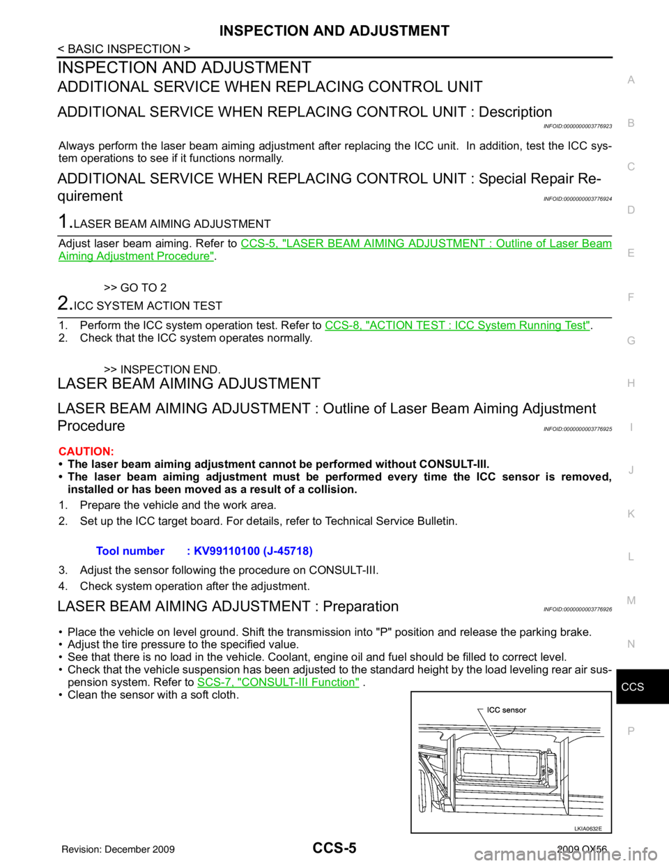
• Clean the sensor with a soft cloth. Tool number : KV99110100 (J-45718)
LKIA0632E
Revision: December 20092009 QX56
Page 697 of 4171
CCS-46
< ECU DIAGNOSIS >
ICC UNIT
ECU DIAGNOSIS
ICC UNIT
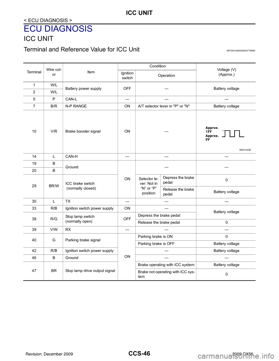
Terminal and Reference Value for ICC UnitINFOID:0000000003776956
Te r m i n a lWire col-
or Item Condition
Voltage (V)
(Approx.)
Ignition
switch Operation
1W/L Battery power supply OFF— Battery voltage
2W/L
5 P CAN-L —— —
7 B/R N-P RANGE ON A/T selector lever in "P" or "N"Battery voltage
10 V/R Brake booster signal ON—
14 L CAN-H —— —
19 B Ground
ON——
20 B
29 BR/W ICC brake switch
(normally closed) Selector le-
ver: Not in “N” or “P” position Depress the brake
pedal
0
Release the brake
pedal Battery voltage
30 L TX —— —
33 R/B Ignition switch power supply ON —
Battery voltage
38 R/G St op la mp sw i tc h
(normally open) OFFDepress the brake pedal
Release the brake pedal
0
39 V/W RX —— —
40 G Parking brake signal
ONParking brake is ON
0
Parking brake is OFF Battery voltage
42 R/B Ignition switch power supply —Battery voltage
46 B Ground ——
47 BR Stop lamp drive output signal Brake operating with ICC system
Battery voltage
Brake not operating with ICC sys-
tem 0
SKIA1243E
Revision: December 20092009 QX56
Page 717 of 4171

CCS-66
< SYMPTOM DIAGNOSIS >
NORMAL OPERATING CONDITION
NORMAL OPERATING CONDITION
DescriptionINFOID:0000000003776969
PRECAUTIONS FOR VEHICLE-TO-VEHICLE DISTANCE CONTROL MODE
• Intelligent Cruise Control is functionally limited. This never support careless driving and low visibility (rain,fog, etc.). Drive the vehicle safely. Keep a safe di stance between vehicles by decreasing the vehicle speed
according to the driving condition etc.
• Intelligent Cruise Control never stop the vehicle autom atically. Intelligent Cruise Control is automatically
released, and the buzzer sounds if any vehicle ahead is not detected when the vehicle speed is approxi-
mately 35 km (21.5 MPH) or less.
• Use this system when the vehicle speed does not extr emely change. This system may not properly function
when any vehicle cuts in, or when the vehicle ahead s uddenly applies the brake. Then, the warning (buzzer
and indication) activates.
• Never use Intelligent Cruise Control in the following conditions.
- A well-trafficed road, and a tight turn. It may cause any accident because the dr iving does not fit to the road condition.
- A slippery road (e.g., freezing, or snowy road) The vehicle may lose the control by wheelspin.
- The vehicle drives in bad whet her (rain, fog, snow etc.).
The distance from the vehicle ahead is not detected pr ecisely if the whether condition is bad. Intelligent
Cruise Control is released automatically if the wiper activates in low or high speed.
- The vehicle receives bright light (sunshine etc.). The distance from the vehicle ahead is not detected pr ecisely if bright light enters in the vehicle.
- Raindrop or snow is on the sensor.
The distance from the vehicle ahead is not detected prec isely if raindrop or snow attaches on the sensor.
- A steep downhill The setting vehicle speed may exceed if Intelligent Cruise Control does not detect the vehicle ahead. The
brake may heat up in the vehicle- to-vehicle distance control mode.
- A repeated uphill and downhill Intelligent Cruise Control may not detect the vehicl e ahead precisely. An accident may occur by tailgating.
- Maintaining proper vehicle distance is difficult due to frequent acceleration/deceleration. It may cause any accident because the driving does not fit to the road condition if keeping a proper vehicle-
to-vehicle distance is difficult.
- When entering in the highway interchange (swerving off the main line),
Unexpected accident may cause if the vehicle ahead drives slower
than the preset vehicle speed. T he vehicle-to-vehicle distance con-
trol mode accelerates automatically because the vehicle ahead is
not detected on the lane if the own vehicle or the vehicle ahead
changes the lane.
• Intelligent Cruise Control does not activate to the parking vehicles, and vehicles driving extremely slow er than the own vehicle. Never
hit the vehicle stopping at a tollgate, or the tail end of traffic jam.
• Intelligent Cruise Control does not activate to the vehicle edging way, and non-vehicle objects (passengers etc.).
• This function detects the reflector of the vehicle ahead. Intelligent Cruise Control may not detect the vehicle
ahead, and keep a proper vehicle-to-vehicle distance in t he following conditions. Drive the vehicle according
to the driving condition.
- The vehicle ahead installs the reflector higher (trailer etc.).
- The rear of the vehicle ahead is extremely dirt.
- The vehicle ahead or vehicle on other lanes splashes water or snow on the road.
- The vehicle ahead provides dark exhaust gas. Smoke blocks the visibility.
- The vehicle ahead attaches film on the reflector. The v ehicle ahead does not install the reflector. The reflec-
tor is broken.
- Extremely heavy load is on the rear seat or in the cargo area.
- The vehicle drives on a repeated uphill and downhill
EL-2980D
Revision: December 20092009 QX56
Page 1064 of 4171
![INFINITI QX56 2009 Factory Owners Manual
DLN-8
< BASIC INSPECTION >[ATX14B]
DIAGNOSIS AND REPAIR WORKFLOW
Does 4WD warning lamp turn ON?
YES >> GO TO CHECK AT IDLE.
NO >> GO TO
DLN-105, "Diagnosis Procedure"
.
CHECK AT IDLE
1.CHECK 4WD SHI](/img/42/57031/w960_57031-1063.png "INFINITI QX56 2009 Factory Owners Manual
DLN-8
< BASIC INSPECTION >[ATX14B]
DIAGNOSIS AND REPAIR WORKFLOW
Does 4WD warning lamp turn ON?
YES >> GO TO CHECK AT IDLE.
NO >> GO TO
DLN-105, \"Diagnosis Procedure\"
.
CHECK AT IDLE
1.CHECK 4WD SHI")
DLN-8
< BASIC INSPECTION >[ATX14B]
DIAGNOSIS AND REPAIR WORKFLOW
Does 4WD warning lamp turn ON?
YES >> GO TO CHECK AT IDLE.
NO >> GO TO
DLN-105, "Diagnosis Procedure"
.
CHECK AT IDLE
1.CHECK 4WD SHIFT INDICATOR LAMP
1. Park vehicle on flat surface and engage the parking brake.
2. Turn ignition switch to OFF position.
3. Move A/T selector lever to P position.
4. Set 4WD shift switch to 2WD position.
5. Start engine.
Does 4WD shift indicator lamp turn ON?
YES >> GO TO 3.
NO >> GO TO 2.
2.CHECK 4WD WARNING LAMP
Check 4WD warning lamp state.
Is 4WD warning lamp turned ON?
YES >> Perform the self-diagnosis. Refer to DLN-18, "CONSULT-III Function (ALL MODE AWD/4WD)".
NO >> Refer to DLN-107, "Diagnosis Procedure"
.
3.CHECK 4WD SHIFT INDICATOR AND 4LO INDICATOR OPERATION
1. Brake pedal depressed.
2. Move A/T selector lever to N position.
3. Set 4WD shift switch to 2WD, AUTO, 4H, 4LO, 4H, AUTO and 2WD in order. (Stay at each switch position for at least 1 sec-
ond.)
Do 4WD shift indicator and 4LO indicator lamps change properly?
Does buzzer sound?
YES >> GO TO CRUISE TEST.
NO >> GO TO DLN-107, "Diagnosis Procedure"
.
CRUISE TEST
1.CHECK INPUT SIGNAL
1. Warm up engine to normal operating temperature.
2. Park vehicle on flat surface.
3. Move A/T selector lever to P position.
4. Set 4WD shift switch to AUTO position.
5. Start engine.
6. Drive vehicle for at least 30 seconds at a speed higher than 20 km/h (12 MPH).
Is 4WD warning lamp turned ON?
On steady>>Perform the self-diagnosis. Refer to DLN-18, "CONSULT-III Function (ALL MODE AWD/4WD)".
WDIA0136E
Revision: December 20092009 QX56