boot INFINITI QX56 2009 Factory Owner's Guide
[x] Cancel search | Manufacturer: INFINITI, Model Year: 2009, Model line: QX56, Model: INFINITI QX56 2009Pages: 4171, PDF Size: 84.65 MB
Page 3088 of 4171
REAR DRIVE SHAFTRAX-13
< DISASSEMBLY AND ASSEMBLY >
CEF
G H
I
J
K L
M A
B
RAX
N
O P
Check the ball sliding surface for any co mpression scars, cracks, or fractures.
Check for any damage to the serrated part. CAUTION:
If any defective conditions are fo und, install a new housing, ball cage, steel ball, and inner race as a
set.
ASSEMBLY
Final Drive Side
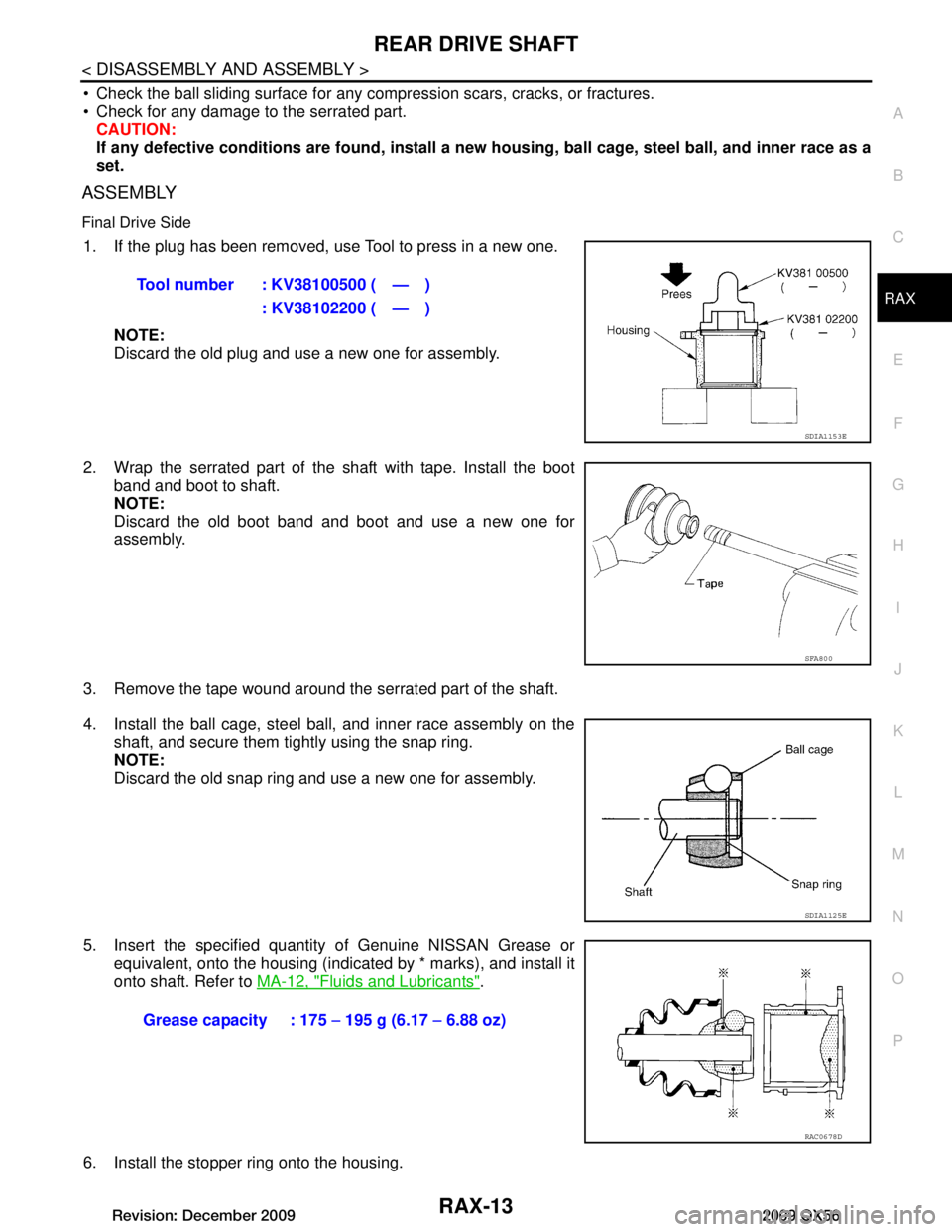
1. If the plug has been removed, use Tool to press in a new one.
NOTE:
Discard the old plug and use a new one for assembly.
2. Wrap the serrated part of the shaft with tape. Install the boot band and boot to shaft.
NOTE:
Discard the old boot band and boot and use a new one for
assembly.
3. Remove the tape wound around the serrated part of the shaft.
4. Install the ball cage, steel ball, and inner race assembly on the shaft, and secure them tightly using the snap ring.
NOTE:
Discard the old snap ring and use a new one for assembly.
5. Insert the specified quantit y of Genuine NISSAN Grease or
equivalent, onto the housing (indicated by * marks), and install it
onto shaft. Refer to MA-12, "Fluids and Lubricants"
.
6. Install the stopper ring onto the housing. Tool number : KV38100500 ( — )
: KV38102200 ( — )
SDIA1153E
SFA800
SDIA1125E
Grease capacity : 175 − 195 g (6.17 − 6.88 oz)
RAC0678D
Revision: December 20092009 QX56
Page 3089 of 4171
RAX-14
< DISASSEMBLY AND ASSEMBLY >
REAR DRIVE SHAFT
7. After installation, pull on the shaft to check engagement between the joint sub-assembly and the stopper
ring.
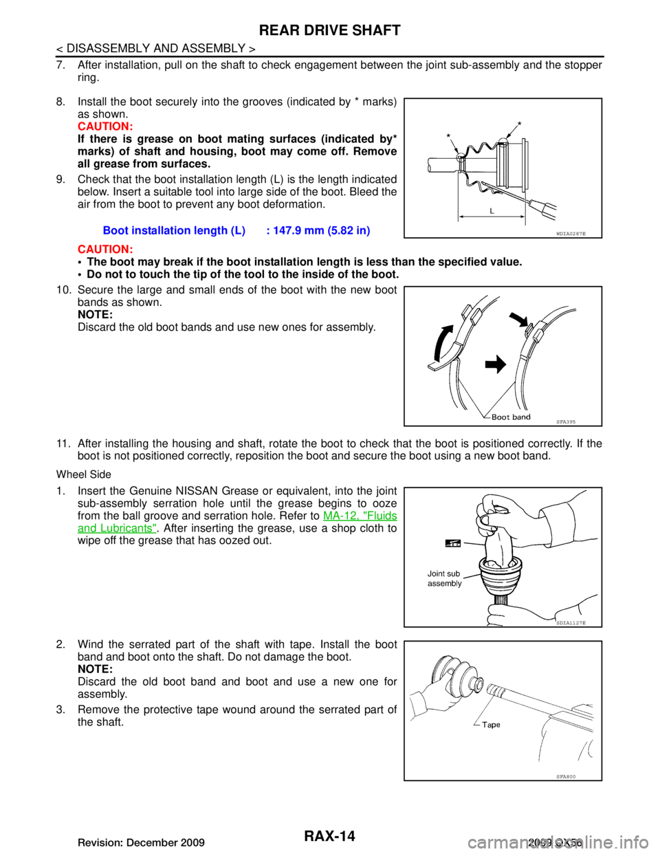
8. Install the boot securely into the grooves (indicated by * marks) as shown.
CAUTION:
If there is grease on boot mating surfaces (indicated by*
marks) of shaft and housing, boot may come off. Remove
all grease from surfaces.
9. Check that the boot installation length (L) is the length indicated below. Insert a suitable tool into large side of the boot. Bleed the
air from the boot to pr event any boot deformation.
CAUTION:
The boot may break if the boot installation length is less than the specified value.
Do not to touch the tip of the t ool to the inside of the boot.
10. Secure the large and small ends of the boot with the new boot bands as shown.
NOTE:
Discard the old boot bands and use new ones for assembly.
11. After installing the housing and shaft, rotate the boot to check that the boot is positioned correctly. If the
boot is not positioned correctly, reposition the boot and secure the boot using a new boot band.
Wheel Side
1. Insert the Genuine NISSAN Grease or equivalent, into the joint
sub-assembly serration hole until the grease begins to ooze
from the ball groove and serration hole. Refer to MA-12, "Fluids
and Lubricants". After inserting the grease, use a shop cloth to
wipe off the grease that has oozed out.
2. Wind the serrated part of the shaft with tape. Install the boot
band and boot onto the shaft. Do not damage the boot.
NOTE:
Discard the old boot band and boot and use a new one for
assembly.
3. Remove the protective tape wound around the serrated part of the shaft. Boot installation length
(L) : 147.9 mm (5.82 in)
WDIA0287E
SFA395
SDIA1127E
SFA800
Revision: December 20092009 QX56
Page 3090 of 4171
REAR DRIVE SHAFTRAX-15
< DISASSEMBLY AND ASSEMBLY >
CEF
G H
I
J
K L
M A
B
RAX
N
O P
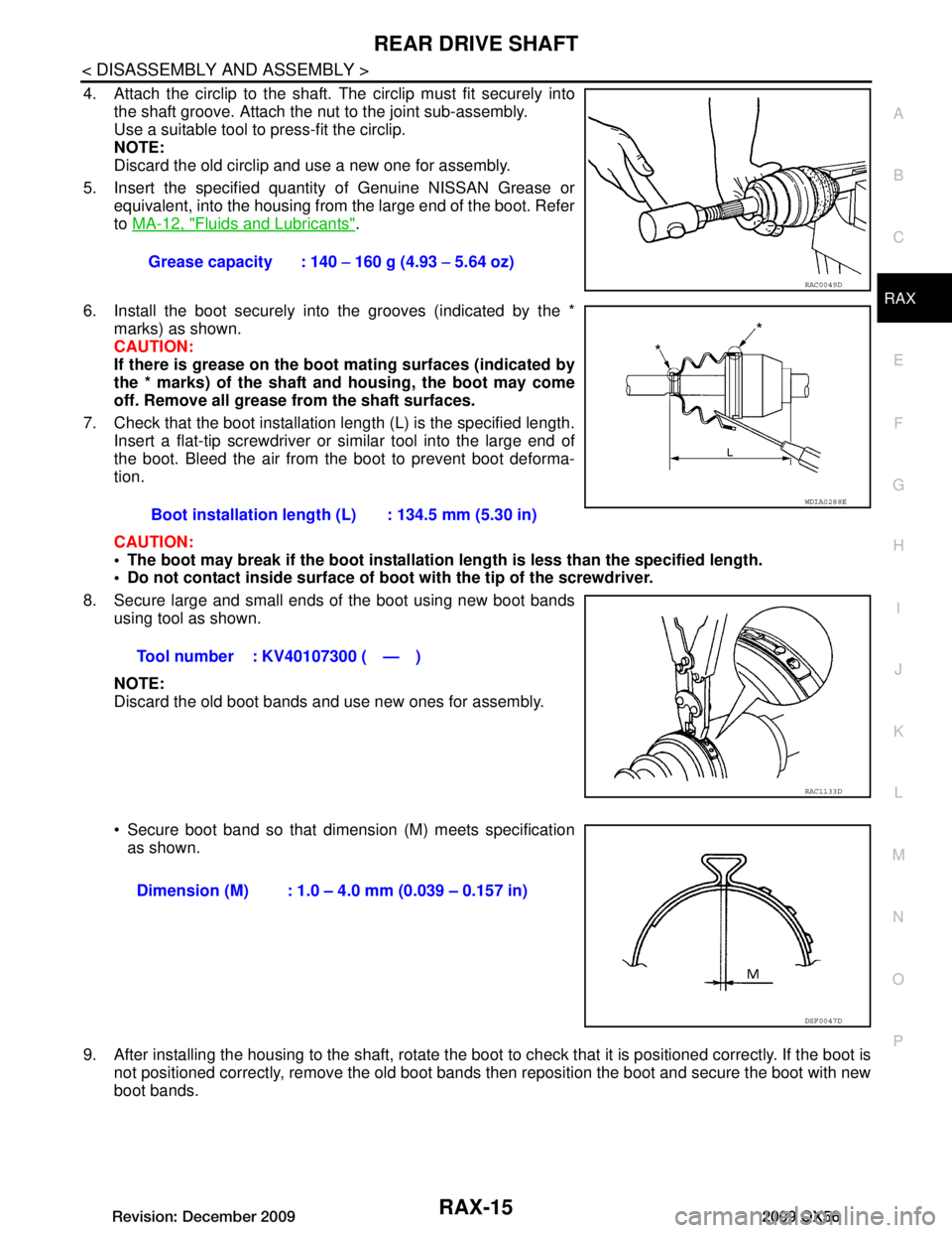
4. Attach the circlip to the shaft. The circlip must fit securely into
the shaft groove. Attach the nut to the joint sub-assembly.
Use a suitable tool to press-fit the circlip.
NOTE:
Discard the old circlip and use a new one for assembly.
5. Insert the specified quantit y of Genuine NISSAN Grease or
equivalent, into the housing from the large end of the boot. Refer
to MA-12, "Fluids and Lubricants"
.
6. Install the boot securely into the grooves (indicated by the * marks) as shown.
CAUTION:
If there is grease on the boot mating surfaces (indicated by
the * marks) of the shaft and housing, the boot may come
off. Remove all grease from the shaft surfaces.
7. Check that the boot installation length (L) is the specified length. Insert a flat-tip screwdriver or similar tool into the large end of
the boot. Bleed the air from the boot to prevent boot deforma-
tion.
CAUTION:
The boot may break if the boot installation length is less than the specified length.
Do not contact inside surface of boot with the tip of the screwdriver.
8. Secure large and small ends of the boot using new boot bands using tool as shown.
NOTE:
Discard the old boot bands and use new ones for assembly.
Secure boot band so that dimension (M) meets specificationas shown.
9. After installing the housing to the shaft, rotate the boot to check that it is positioned correctly. If the boot is
not positioned correctly, remove the old boot bands then reposition the boot and secure the boot with new
boot bands. Grease capacity : 140
− 160 g (4.93 − 5.64 oz)
RAC0049D
Boot installation length (L) : 134.5 mm (5.30 in)
Tool number : KV40107300 ( — )
WDIA0288E
RAC1133D
Dimension (M) : 1.0 – 4.0 mm (0.039 – 0.157 in)
DSF0047D
Revision: December 20092009 QX56
Page 3091 of 4171
RAX-16
< SERVICE DATA AND SPECIFICATIONS (SDS)
SERVICE DATA AND SPECIFICATIONS (SDS)
SERVICE DATA AND SPECIFICATIONS (SDS)
SERVICE DATA AND SPECIFICATIONS (SDS)
Wheel BearingINFOID:0000000003772263
Drive ShaftINFOID:0000000003772264
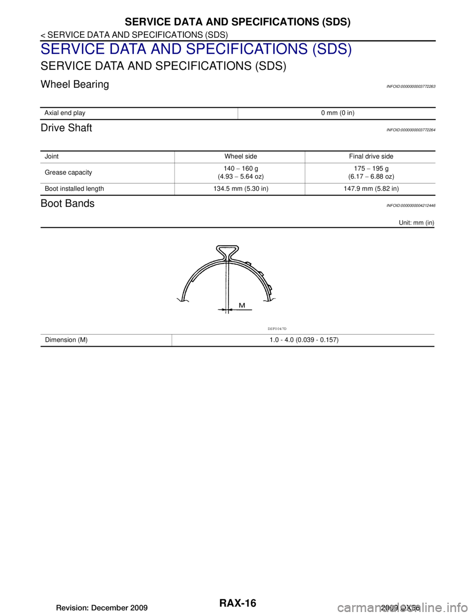
Boot BandsINFOID:0000000004212446
Unit: mm (in)
Axial end play0 mm (0 in)
Joint Wheel side Final drive side
Grease capacity140
− 160 g
(4.93 − 5.64 oz) 175
− 195 g
(6.17 − 6.88 oz)
Boot installed length 134.5 mm (5.30 in) 147.9 mm (5.82 in)
Dimension (M) 1.0 - 4.0 (0.039 - 0.157)
DSF0047D
Revision: December 20092009 QX56
Page 3163 of 4171
SHOCK ABSORBERRSU-15
< REMOVAL AND INSTALLATION >
C
DF
G H
I
J
K L
M A
B
RSU
N
O P
SHOCK ABSORBER
Removal and InstallationINFOID:0000000005889873
REMOVAL
1. Remove the wheel and tire assembly using power tool. Refer to WT-41, "Adjustment".
2. If equipped with the rear load leveling air suspens ion system, use CONSULT-III "EXHAUST SOLENOID"
active test to release the air pressure from the rear load leveling air suspension system.
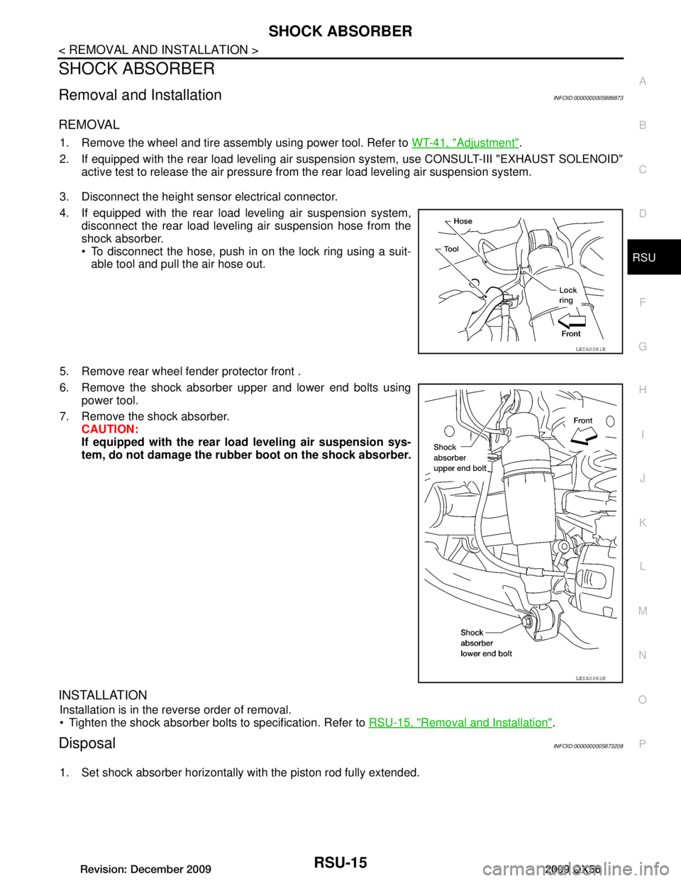
3. Disconnect the height sensor electrical connector.
4. If equipped with the rear load leveling air suspension system, disconnect the rear load leveling air suspension hose from the
shock absorber.
To disconnect the hose, push in on the lock ring using a suit-able tool and pull the air hose out.
5. Remove rear wheel fender protector front .
6. Remove the shock absorber upper and lower end bolts using power tool.
7. Remove the shock absorber. CAUTION:
If equipped with the rear lo ad leveling air suspension sys-
tem, do not damage the rubber boot on the shock absorber.
INSTALLATION
Installation is in the reverse order of removal.
Tighten the shock absorber bolts to specification. Refer to RSU-15, "Removal and Installation"
.
DisposalINFOID:0000000005873208
1. Set shock absorber horizontally with the piston rod fully extended.
LEIA0081E
LEIA0082E
Revision: December 20092009 QX56
Page 3167 of 4171
FRONT LOWER LINKRSU-19
< REMOVAL AND INSTALLATION >
C
DF
G H
I
J
K L
M A
B
RSU
N
O P
FRONT LOWER LINK
Removal and InstallationINFOID:0000000005889875
REMOVAL
1. Remove the wheel and tire assembly using power tool.
2. If equipped with rear load leveling air suspension system, use CONSULT-III “EXHAUST SOLENOID”
active test to release the air pressure from the rear load leveling air suspension system.
3. Set suitable jack to support rear lower link.
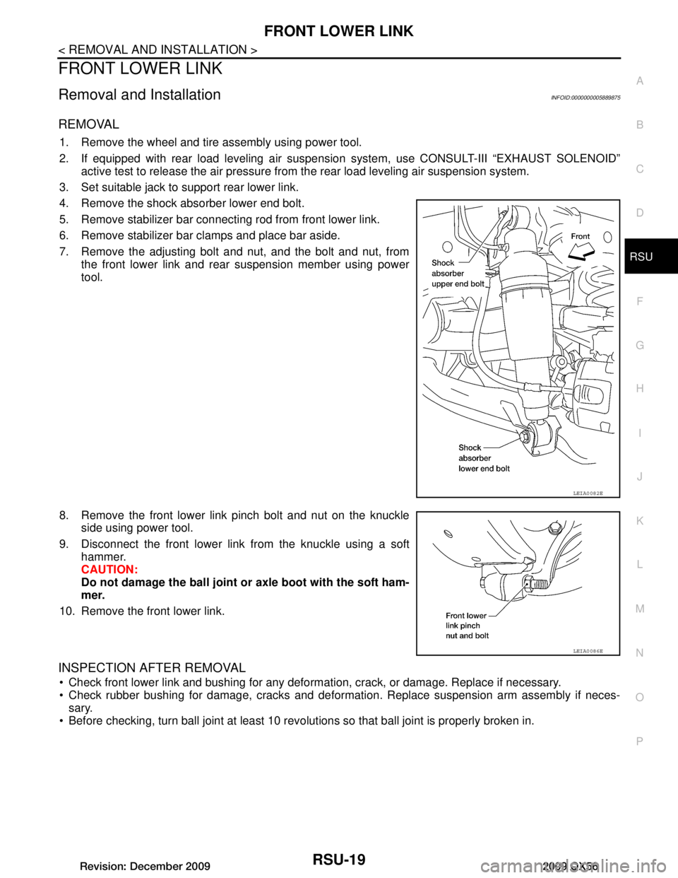
4. Remove the shock absorber lower end bolt.
5. Remove stabilizer bar connecting rod from front lower link.
6. Remove stabilizer bar clamps and place bar aside.
7. Remove the adjusting bolt and nut, and the bolt and nut, from the front lower link and rear suspension member using power
tool.
8. Remove the front lower link pinch bolt and nut on the knuckle side using power tool.
9. Disconnect the front lower link from the knuckle using a soft hammer.
CAUTION:
Do not damage the ball joint or axle boot with the soft ham-
mer.
10. Remove the front lower link.
INSPECTION AFTER REMOVAL
Check front lower link and bushing for any deformation, crack, or damage. Replace if necessary.
Check rubber bushing for damage, cracks and deformation. Replace suspension arm assembly if neces-
sary.
Before checking, turn ball joint at least 10 revo lutions so that ball joint is properly broken in.
LEIA0082E
LEIA0086E
Revision: December 20092009 QX56
Page 3596 of 4171
PREPARATIONST-5
< PREPARATION >
C
DE
F
H I
J
K L
M A
B
ST
N
O P
PREPARATION
PREPARATION
Special Service ToolINFOID:0000000003775117
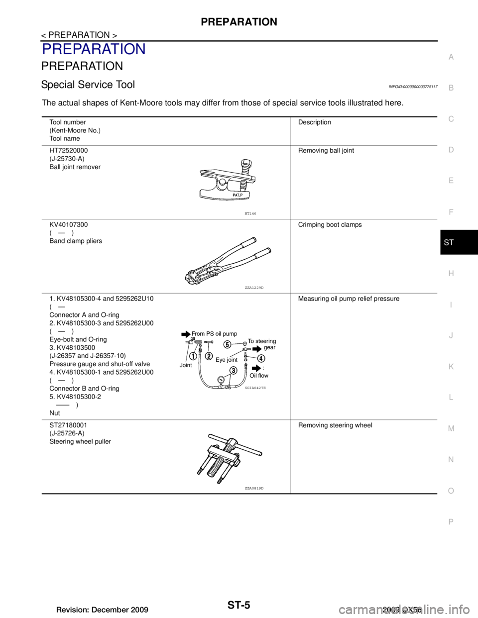
The actual shapes of Kent-Moore tools may differ fr om those of special service tools illustrated here.
Tool number
(Kent-Moore No.)
Tool name Description
HT72520000
(J-25730-A)
Ball joint remover Removing ball joint
KV40107300
(—)
Band clamp pliers Crimping boot clamps
1. KV48105300-4 and 5295262U10
(—
Connector A and O-ring
2. KV48105300-3 and 5295262U00
(—)
Eye-bolt and O-ring
3. KV48103500
(J-26357 and J-26357-10)
Pressure gauge and shut-off valve
4. KV48105300-1 and 5295262U00
(—)
Connector B and O-ring
5. KV48105300-2 —— )
Nut Measuring oil pump relief pressure
ST27180001
(J-25726-A)
Steering wheel puller Removing steering wheel
NT146
ZZA1229D
SGIA0427E
ZZA0819D
Revision: December 20092009 QX56
Page 3604 of 4171
POWER STEERING FLUIDST-13
< ON-VEHICLE MAINTENANCE >
C
DE
F
H I
J
K L
M A
B
ST
N
O P
ON-VEHICLE MAINTENANCE
POWER STEERING FLUID
Checking Fluid LevelINFOID:0000000004187604
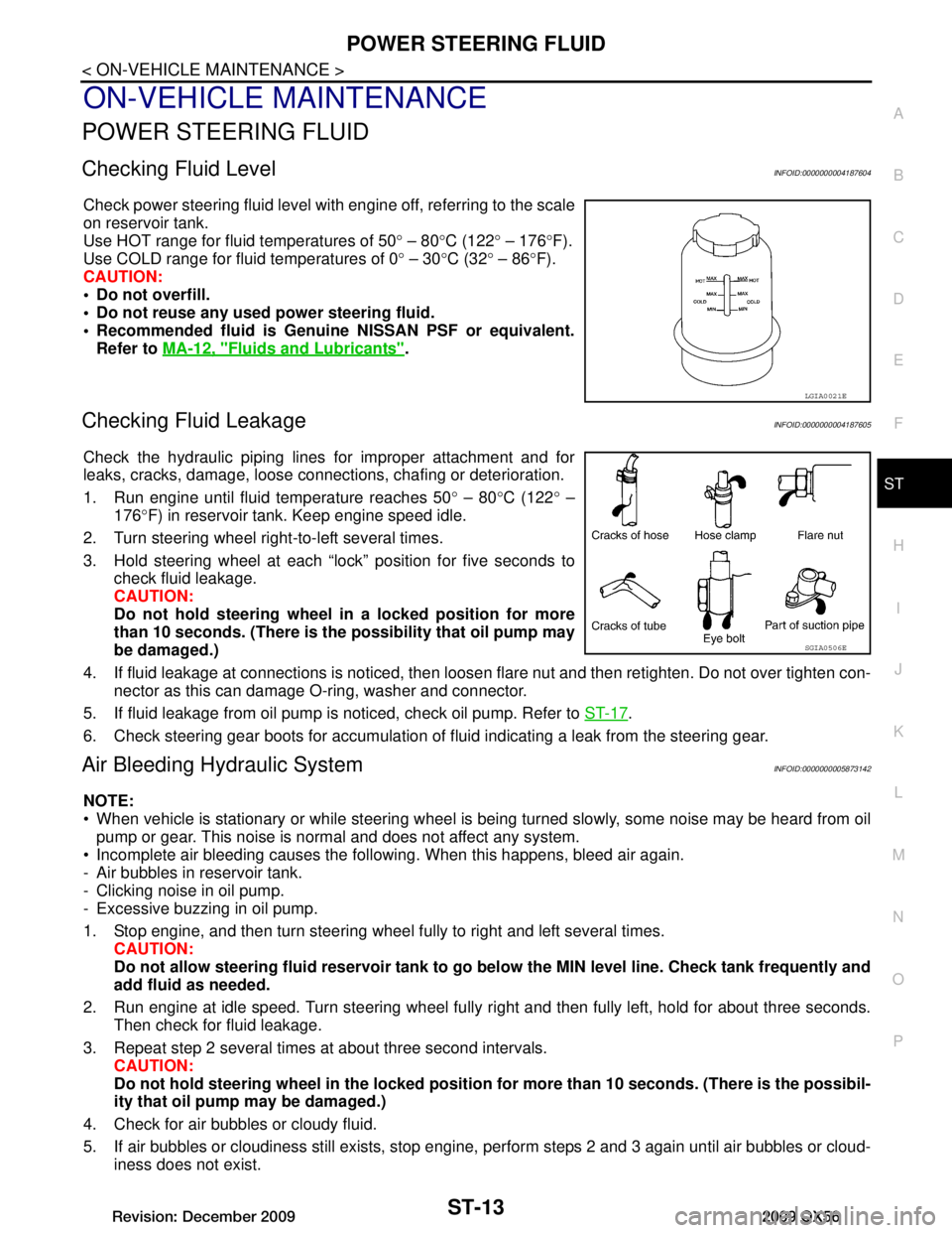
Check power steering fluid level with engine off, referring to the scale
on reservoir tank.
Use HOT range for fluid temperatures of 50 ° – 80 °C (122 ° – 176 °F).
Use COLD range for fluid temperatures of 0 ° – 30 °C (32 ° – 86 °F).
CAUTION:
Do not overfill.
Do not reuse any used power steering fluid.
Recommended fluid is Genuine NISSAN PSF or equivalent. Refer to MA-12, "Fluids and Lubricants"
.
Checking Fluid LeakageINFOID:0000000004187605
Check the hydraulic piping lines for improper attachment and for
leaks, cracks, damage, loose connections, chafing or deterioration.
1. Run engine until fluid temperature reaches 50 ° – 80 °C (122 ° –
176 °F) in reservoir tank. Keep engine speed idle.
2. Turn steering wheel right-to-left several times.
3. Hold steering wheel at each “lock” position for five seconds to check fluid leakage.
CAUTION:
Do not hold steering wheel in a locked position for more
than 10 seconds. (There is the possibility that oil pump may
be damaged.)
4. If fluid leakage at connections is noticed, then loos en flare nut and then retighten. Do not over tighten con-
nector as this can damage O-ring, washer and connector.
5. If fluid leakage from oil pump is noticed, check oil pump. Refer to ST-17
.
6. Check steering gear boots for accumulation of fluid indicating a leak from the steering gear.
Air Bleeding Hydraulic SystemINFOID:0000000005873142
NOTE:
When vehicle is stationary or while steering wheel is being turned slowly, some noise may be heard from oil pump or gear. This noise is normal and does not affect any system.
Incomplete air bleeding causes the fo llowing. When this happens, bleed air again.
- Air bubbles in reservoir tank.
- Clicking noise in oil pump.
- Excessive buzzing in oil pump.
1. Stop engine, and then turn steering wheel fully to right and left several times. CAUTION:
Do not allow steering fluid reservoir tank to go below the MIN level line. Check tank frequently and
add fluid as needed.
2. Run engine at idle speed. Turn steering wheel fully right and then fully left, hold for about three seconds.
Then check for fluid leakage.
3. Repeat step 2 several times at about three second intervals. CAUTION:
Do not hold steeri ng wheel in the locked position for more than 10 seconds. (There is the possibil-
ity that oil pump may be damaged.)
4. Check for air bubbles or cloudy fluid.
5. If air bubbles or cloudiness still exists, stop engine, perform steps 2 and 3 again until air bubbles or cloud-
iness does not exist.
LGIA0021E
SGIA0506E
Revision: December 20092009 QX56
Page 3611 of 4171
ST-20
< REMOVAL AND INSTALLATION >
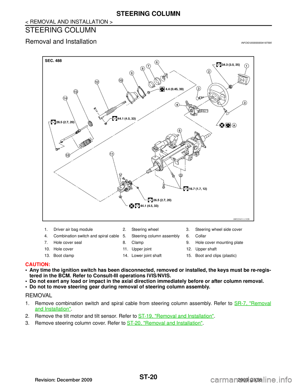
STEERING COLUMN
STEERING COLUMN
Removal and InstallationINFOID:0000000004187595
CAUTION:
Any time the ignition switch has been disconnected, removed or inst alled, the keys must be re-regis-
tered in the BCM. Refer to Consult-III operations IVIS/NVIS.
Do not exert any load or impact in the axial dir ection immediately before or after column removal.
Do not to move steering gear during removal of steering column assembly.
REMOVAL
1. Remove combination switch and spiral cable from steering column assembly. Refer to SR-7, "Removal
and Installation".
2. Remove the tilt motor and tilt sensor. Refer to ST-19, "Removal and Installation"
.
3. Remove steering column cover. Refer to ST-20, "Removal and Installation"
.
1. Driver air bag module 2. Steering wheel 3. Steering wheel side cover
4. Combination switch and spiral cable 5. Steering column assembly 6. Collar
7. Hole cover seal 8. Clamp 9. Hole cover mounting plate
10. Hole cover 11. Upper joint 12. Upper shaft
13. Boot clamp 14. Lower joint shaft 15. Boot and clips (plastic)
AWGIA0113GB
Revision: December 20092009 QX56
Page 3615 of 4171
ST-24
< REMOVAL AND INSTALLATION >
POWER STEERING GEAR AND LINKAGE
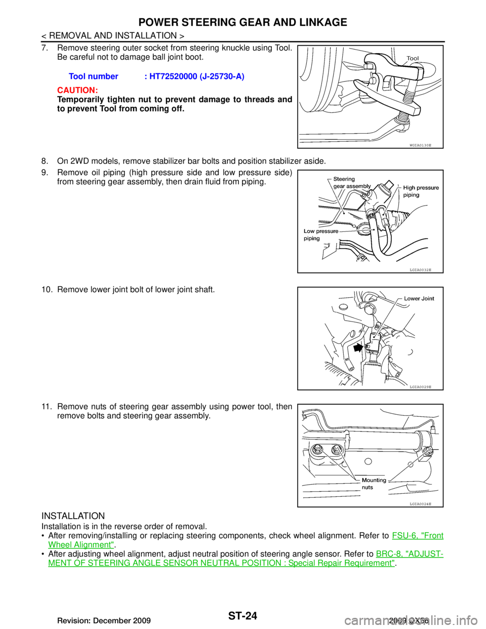
7. Remove steering outer socket from steering knuckle using Tool.Be careful not to damage ball joint boot.
CAUTION:
Temporarily tighten nut to prevent damage to threads and
to prevent Tool from coming off.
8. On 2WD models, remove stabilizer bar bolts and position stabilizer aside.
9. Remove oil piping (high pressure side and low pressure side) from steering gear assembly, then drain fluid from piping.
10. Remove lower joint bolt of lower joint shaft.
11. Remove nuts of steering gear assembly using power tool, then remove bolts and steering gear assembly.
INSTALLATION
Installation is in the reverse order of removal.
After removing/installing or replacing steering components, check wheel alignment. Refer to FSU-6, "Front
Wheel Alignment".
After adjusting wheel alignment, adjust neutral position of steering angle sensor. Refer to BRC-8, "ADJUST-
MENT OF STEERING ANGLE SENSOR NEUTRAL POSITION : Special Repair Requirement".
Tool number : HT72520000 (J-25730-A)
WGIA0130E
LGIA0032E
LGIA0029E
LGIA0024E
Revision: December 20092009 QX56