wheel bolts INFINITI QX56 2009 Factory Owner's Guide
[x] Cancel search | Manufacturer: INFINITI, Model Year: 2009, Model line: QX56, Model: INFINITI QX56 2009Pages: 4171, PDF Size: 84.65 MB
Page 3162 of 4171
RSU-14
< REMOVAL AND INSTALLATION >
REAR SUSPENSION MEMBER
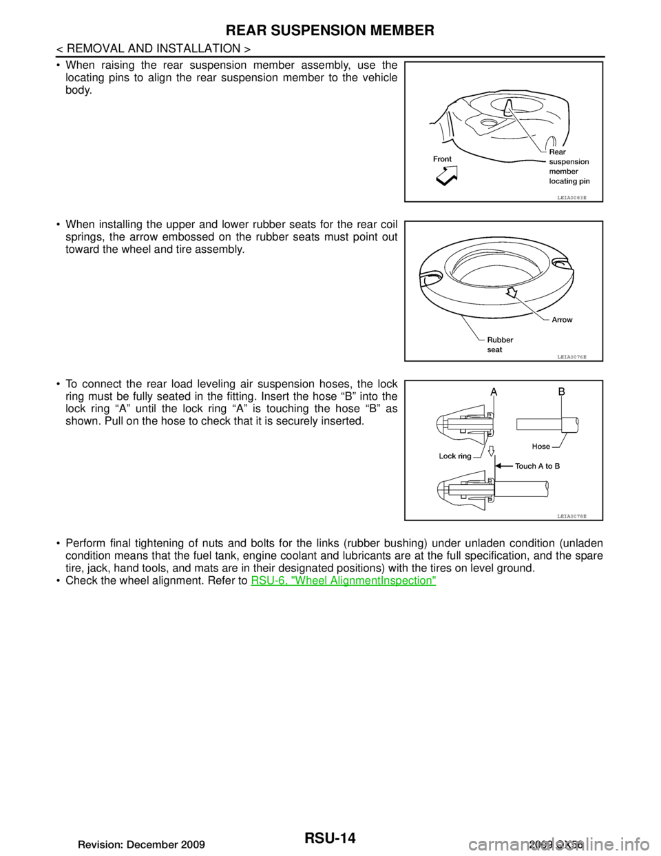
When raising the rear suspension member assembly, use thelocating pins to align the rear suspension member to the vehicle
body.
When installing the upper and lower rubber seats for the rear coil springs, the arrow embossed on the rubber seats must point out
toward the wheel and tire assembly.
To connect the rear load leveling air suspension hoses, the lock ring must be fully seated in the fitt ing. Insert the hose “B” into the
lock ring “A” until the lock ring “A” is touching the hose “B” as
shown. Pull on the hose to check that it is securely inserted.
Perform final tightening of nuts and bolts for the links (rubber bushing) under unladen condition (unladen condition means that the fuel tank, engine coolant and l ubricants are at the full specification, and the spare
tire, jack, hand tools, and mats are in their designated positions) with the tires on level ground.
Check the wheel alignment. Refer to RSU-6, "Wheel AlignmentInspection"
LEIA0083E
LEIA0076E
LEIA0078E
Revision: December 20092009 QX56
Page 3163 of 4171
SHOCK ABSORBERRSU-15
< REMOVAL AND INSTALLATION >
C
DF
G H
I
J
K L
M A
B
RSU
N
O P
SHOCK ABSORBER
Removal and InstallationINFOID:0000000005889873
REMOVAL
1. Remove the wheel and tire assembly using power tool. Refer to WT-41, "Adjustment".
2. If equipped with the rear load leveling air suspens ion system, use CONSULT-III "EXHAUST SOLENOID"
active test to release the air pressure from the rear load leveling air suspension system.
3. Disconnect the height sensor electrical connector.
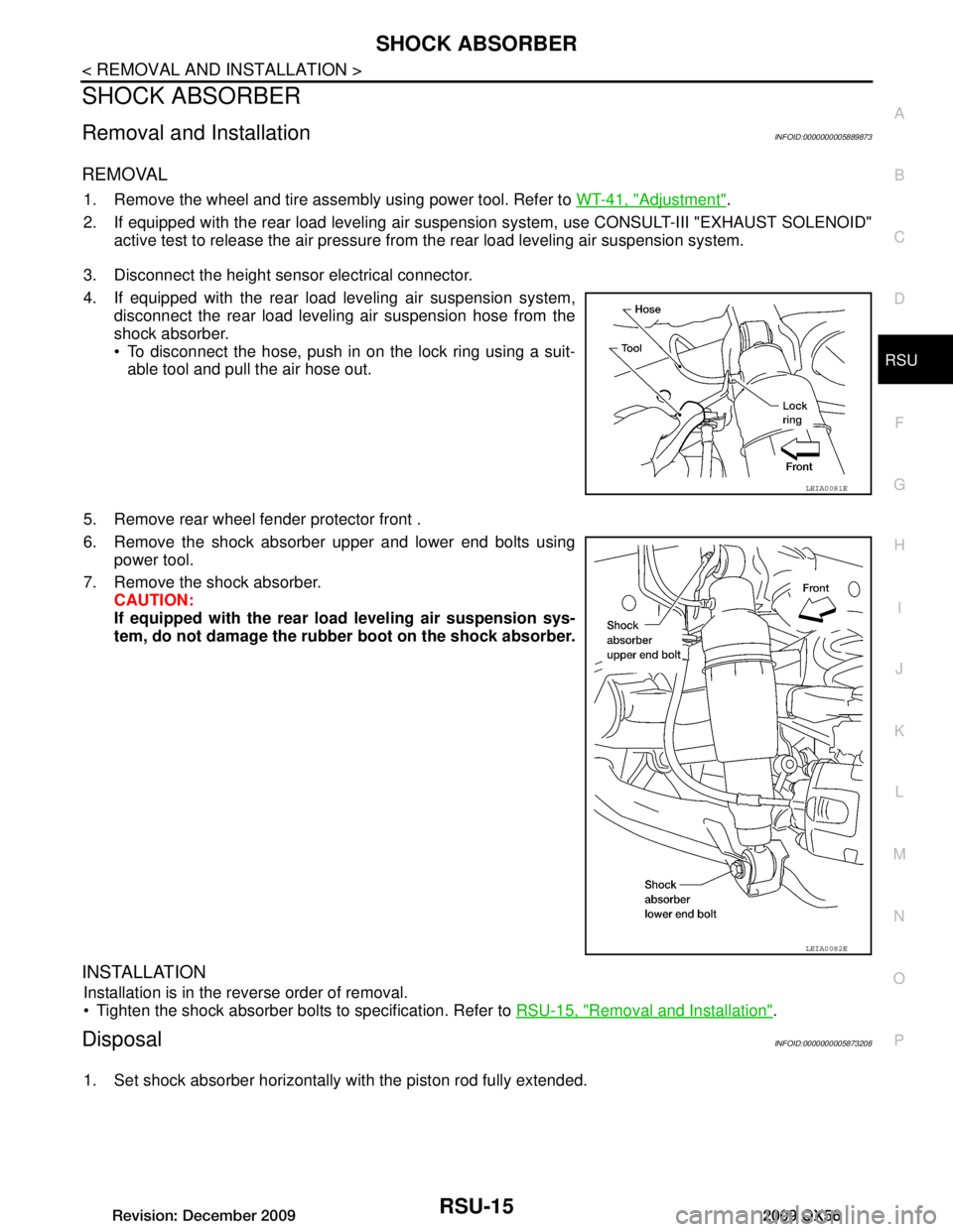
4. If equipped with the rear load leveling air suspension system, disconnect the rear load leveling air suspension hose from the
shock absorber.
To disconnect the hose, push in on the lock ring using a suit-able tool and pull the air hose out.
5. Remove rear wheel fender protector front .
6. Remove the shock absorber upper and lower end bolts using power tool.
7. Remove the shock absorber. CAUTION:
If equipped with the rear lo ad leveling air suspension sys-
tem, do not damage the rubber boot on the shock absorber.
INSTALLATION
Installation is in the reverse order of removal.
Tighten the shock absorber bolts to specification. Refer to RSU-15, "Removal and Installation"
.
DisposalINFOID:0000000005873208
1. Set shock absorber horizontally with the piston rod fully extended.
LEIA0081E
LEIA0082E
Revision: December 20092009 QX56
Page 3165 of 4171

SUSPENSION ARMRSU-17
< REMOVAL AND INSTALLATION >
C
DF
G H
I
J
K L
M A
B
RSU
N
O P
SUSPENSION ARM
Removal and InstallationINFOID:0000000005889874
REMOVAL
1. If equipped with rear load leveling air suspension system, use CONSULT-III “EXHAUST SOLENOID”
active test to release the air pressure from the rear load leveling air suspension system.
2. If equipped with the rear load leveling air suspension system, disconnect the electrical connectors for the
height sensor and the rear load leveling air suspension compressor assembly.
3. If equipped with the rear load leveling air suspension system, unclip the rubber cover to access the rear
load leveling air suspension compressor assembly.
4. If equipped with the rear load leveling air suspension system, disconnect the rear load leveling air suspension hoses at the
rear load leveling air suspension compressor assembly.
To disconnect the hoses, push in on the lock ring using a suit-able tool and pull the hose out.
5. Remove both of the rear wheel and tire assemblies using power tool.
6. Remove the brake caliper without disconnecting the brake hoses, using power tool. Reposition the brake caliper out of the
way using a suitable wire. Refer to BR-36, "Removal and Instal-
lation of Brake Caliper and Disc Rotor".
CAUTION:
Do not crimp or stretch the brake hose when re positioning the brake caliper out of the way.
Do not press brake pedal while the brake caliper is removed.
7. Remove the spare tire.
8. Remove both lower shock bolts.
9. Disconnect the two rear ABS sensor electrical connectors.
10. Remove the two rear drive shafts at t he rear final drive and support drive shafts.
11. Remove the rear final drive. Refer to DLN-250, "Removal and Installation"
.
12. Remove the EVAP canister bolt from the top of the rear suspension member.
13. Disconnect the parking brake cables from t he brackets on the rear suspension member.
14. Disconnect parking brake cables at equalizer. Refer to PB-7, "Removal and Installation"
.
15. Set a suitable jack to support each of the rear lower links and the coil spring tension.
16. Remove both of the rear lower link outer bolts and lower the jack to remove the rear coil springs. If equipped with the rear load leveling air suspension systemremove the height sensor bracket bolt from the LH rear lower link.
LEIA0074E
LEIA0077E
Revision: December 20092009 QX56
Page 3166 of 4171
RSU-18
< REMOVAL AND INSTALLATION >
SUSPENSION ARM
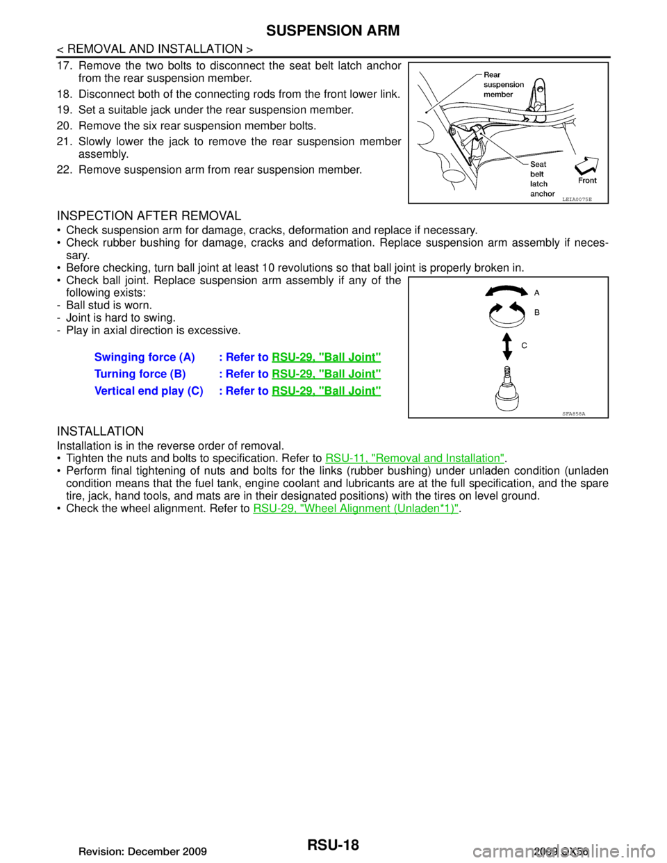
17. Remove the two bolts to disconnect the seat belt latch anchorfrom the rear suspension member.
18. Disconnect both of the connecting rods from the front lower link.
19. Set a suitable jack under the rear suspension member.
20. Remove the six rear suspension member bolts.
21. Slowly lower the jack to remove the rear suspension member assembly.
22. Remove suspension arm from rear suspension member.
INSPECTION AFTER REMOVAL
Check suspension arm for damage, cracks, deformation and replace if necessary.
Check rubber bushing for damage, cracks and deformation. Replace suspension arm assembly if neces- sary.
Before checking, turn ball joint at least 10 revolutions so that ball joint is properly broken in.
Check ball joint. Replace suspension arm assembly if any of the following exists:
- Ball stud is worn.
- Joint is hard to swing.
- Play in axial direction is excessive.
INSTALLATION
Installation is in the reverse order of removal.
Tighten the nuts and bolts to specification. Refer to RSU-11, "Removal and Installation"
.
Perform final tightening of nuts and bolts for the links (rubber bushing) under unladen condition (unladen
condition means that the fuel tank, engine coolant and l ubricants are at the full specification, and the spare
tire, jack, hand tools, and mats are in their designated positions) with the tires on level ground.
Check the wheel alignment. Refer to RSU-29, "Wheel Alignment (Unladen
*1)".
LEIA0075E
Swinging force (A) : Refer to RSU-29, "Ball Joint"
Turning force (B) : Refer to RSU-29, "Ball Joint"
Vertical end play (C) : Refer to RSU-29, "Ball Joint"
SFA858A
Revision: December 20092009 QX56
Page 3168 of 4171
RSU-20
< REMOVAL AND INSTALLATION >
FRONT LOWER LINK
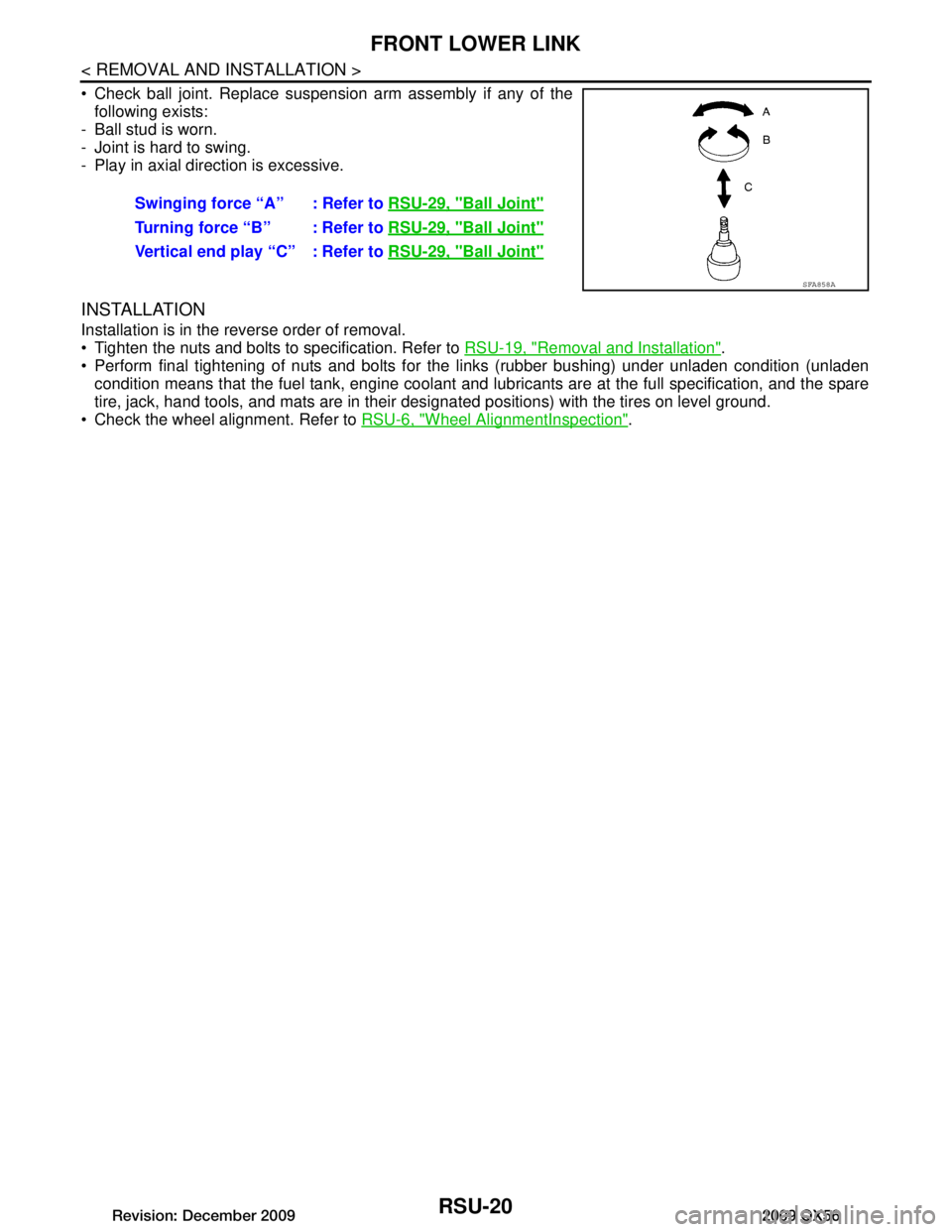
Check ball joint. Replace suspension arm assembly if any of thefollowing exists:
- Ball stud is worn.
- Joint is hard to swing.
- Play in axial direction is excessive.
INSTALLATION
Installation is in the reverse order of removal.
Tighten the nuts and bolts to specification. Refer to RSU-19, "Removal and Installation"
.
Perform final tightening of nuts and bolts for the links (rubber bushing) under unladen condition (unladen condition means that the fuel tank, engine coolant and l ubricants are at the full specification, and the spare
tire, jack, hand tools, and mats are in their designated positions) with the tires on level ground.
Check the wheel alignment. Refer to RSU-6, "Wheel AlignmentInspection"
.
Swinging force “A” : Refer to
RSU-29, "Ball Joint"
Turning force “B” : Refer to RSU-29, "Ball Joint"
Vertical end play “C” : Refer to RSU-29, "Ball Joint"
SFA858A
Revision: December 20092009 QX56
Page 3170 of 4171

RSU-22
< REMOVAL AND INSTALLATION >
REAR LOWER LINK & COIL SPRING
8. Slowly lower the suitable jack to release the coil spring tension. Then remove the upper rubber seat, coil
spring and lower rubber seat from the rear lower link.
9. Remove the rear lower link adjusting bolt and nut from the rear suspension member using power tool, then remove the rear
lower link.
INSPECTION AFTER REMOVAL
Check the coil spring and rubber seats for deformation, cracks, or other damage and replace if necessary.
INSTALLATION
Installation is in the reverse order of removal.
Tighten the nuts and bolts to specification. Refer to RSU-21, "Removal and Installation"
.
When installing the upper and lower rubber seats for the rear coil springs, the arrow embossed on the rubber seats must point out
toward the wheel and tire assembly.
After installing the rear lower link and coil spring, check the wheel alignment and adjust if necessary. Refer to RSU-6, "Wheel Align-
mentInspection".
LEIA0009E
LEIA0076E
Revision: December 20092009 QX56
Page 3478 of 4171

DRIVER AIR BAG MODULESR-5
< ON-VEHICLE REPAIR >
C
DE
F
G
I
J
K L
M A
B
SR
N
O P
ON-VEHICLE REPAIR
DRIVER AIR BAG MODULE
Removal and InstallationINFOID:0000000003775157
REMOVAL
CAUTION:
• Do not attempt to repair or replace damaged direct-connect SRS component connectors. If a driver air bag direct-connect harness connector is damaged, the spiral cable must be replaced.
• Before servicing the SRS, turn ignition switch OFF, disconnect both battery terminals and wait at
least three minutes.
• When servicing the SRS, do not work from directly in front of air bag module.
1. Disconnect both the negative and positive battery te rminals, then wait at least three minutes.
2. Remove the left and right side bolts.
3. Lift the driver air bag module from the steering wheel.
4. Disconnect the air bag harness and horn connectors, then remove the driver air bag module. • For removal/installation of the direct-connect SRS connectors, refer to SRC-9, "
Direct-connect SRS
Component Connectors".
CAUTION:
• When servicing the SRS, do not work from directly in front of air bag module.
• Always place air bag module wi th pad side facing upward.
• Do not insert any foreign object s (screwdriver, etc.) into air
bag module or harness connectors.
• Do not disassemble air bag module.
• Do not use old bolts after removal; replace with new bolts.
• Do not expose the air bag mo dule to temperatures exceeding
90° C (194 °F).
1. Horn harness 2. Steering wheel hook3. Inflator harness
4. Side lids RH/LH 5. Driver air bag module6. Steering wheel
WHIA0159E
LHIA0052E
Revision: December 20092009 QX56
Page 3597 of 4171
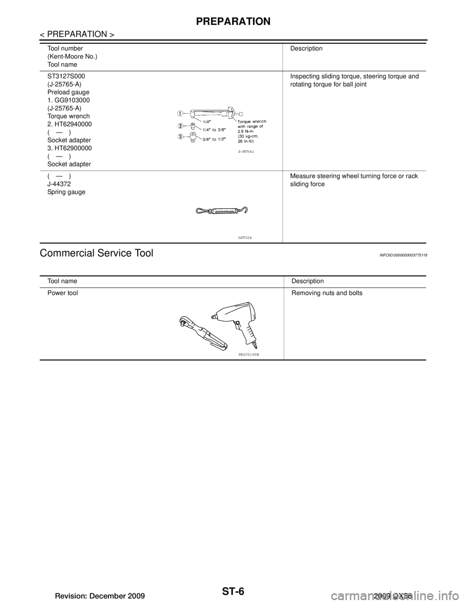
ST-6
< PREPARATION >
PREPARATION
Commercial Service Tool
INFOID:0000000003775118
ST3127S000
(J-25765-A)
Preload gauge
1. GG9103000
(J-25765-A)
Torque wrench
2. HT62940000
(—)
Socket adapter
3. HT62900000
(—)
Socket adapter Inspecting sliding torque, steering torque and
rotating torque for ball joint
(—)
J-44372
Spring gauge Measure steering wheel turning force or rack
sliding force
Tool number
(Kent-Moore No.)
Tool name
Description
S-NT541
LST024
Tool name
Description
Power tool Removing nuts and bolts
PBIC0190E
Revision: December 20092009 QX56
Page 3612 of 4171

STEERING COLUMNST-21
< REMOVAL AND INSTALLATION >
C
DE
F
H I
J
K L
M A
B
ST
N
O P
4. Remove lock nut and bolt, then separate upper shaft from upper joint.
5. Remove two nuts and two bolts, then remove steering column assembly from steering member.
6. Remove hole cover seal and clamp.
7. Remove mounting nuts, then remove hole cover from dash panel.
8. Raise vehicle, then remove mounting bolt (lower side) of lower joint shaft and remove lower joint shaft and upper shaft as an
assembly.
INSPECTION AFTER REMOVAL
Check for damage to steering column jacket tube. If damage is found, replace steering column with new
one.
If vehicle has been in a collision, check column length (L), (L
1) and L2) as shown. If out of specification,
replace steering column with new one.
LGIA0027E
LGIA0028E
LGIA0029E
Steering column length
L : Refer to ST-36, "Steering
Wheel"
L1: Refer to ST-36, "Steering
Wheel"
L2: Refer to ST-36, "Steering
Wheel"
WGIA0080E
Revision: December 20092009 QX56
Page 3613 of 4171

ST-22
< REMOVAL AND INSTALLATION >
STEERING COLUMN
Check for proper lubrication, apply grease as necessary.
INSTALLATION
Installation is in the reverse order of removal.
CAUTION:
When installing the steering column, finger-tighten all of the lower bracket and joint retaining bolts;
then tighten them to specifi cation. Do not apply undue st ress to the steering column.
The lower nut on the upper joint may not be reused.
After installation, turn steering wheel to make sure it moves smoothly. Make sure the number of turns are the
same from the straight-forward position to left and right locks. Make sure that the steering wheel is in a neu-
tral position when driving straight ahead.
When installing steering column to steering mem ber, install nut from front side of vehicle.
INSPECTION AFTER INSTALLATION
After installing steering column to vehicle, check tilt device operation range is within specification.
Check if steering wheel operation can turn to the end of the left and right stops smoothly.
SGIA0475E
Range "A" : ST-36, "Steering Col-
umn"
WGIA0083E
Revision: December 20092009 QX56