lock INFINITI QX56 2009 Factory Workshop Manual
[x] Cancel search | Manufacturer: INFINITI, Model Year: 2009, Model line: QX56, Model: INFINITI QX56 2009Pages: 4171, PDF Size: 84.65 MB
Page 457 of 4171
BRAKE BOOSTERBR-27
< ON-VEHICLE REPAIR >
C
DE
G H
I
J
K L
M A
B
BR
N
O P
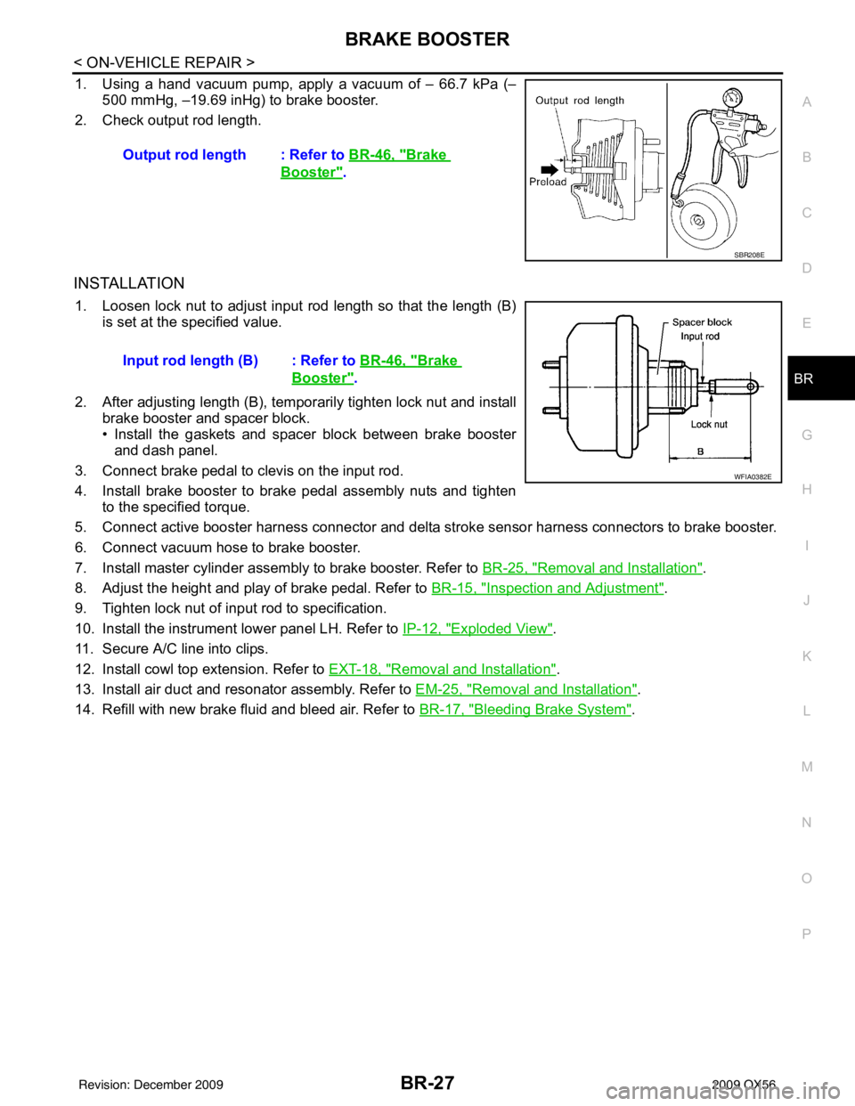
1. Using a hand vacuum pump, apply a vacuum of – 66.7 kPa (– 500 mmHg, –19.69 inHg) to brake booster.
2. Check output rod length.
INSTALLATION
1. Loosen lock nut to adjust input r od length so that the length (B)
is set at the specified value.
2. After adjusting length (B), temporarily tighten lock nut and install brake booster and spacer block.
• Install the gaskets and spacer block between brake boosterand dash panel.
3. Connect brake pedal to clevis on the input rod.
4. Install brake booster to brake pedal assembly nuts and tighten to the specified torque.
5. Connect active booster harness connector and delta st roke sensor harness connectors to brake booster.
6. Connect vacuum hose to brake booster.
7. Install master cylinder assembly to brake booster. Refer to BR-25, "
Removal and Installation".
8. Adjust the height and play of brake pedal. Refer to BR-15, "
Inspection and Adjustment".
9. Tighten lock nut of input rod to specification.
10. Install the instrument lower panel LH. Refer to IP-12, "
Exploded View".
11. Secure A/C line into clips.
12. Install cowl top extension. Refer to EXT-18, "
Removal and Installation".
13. Install air duct and resonator assembly. Refer to EM-25, "
Removal and Installation".
14. Refill with new brake fluid and bleed air. Refer to BR-17, "
Bleeding Brake System".
Output rod length : Refer to
BR-46, "
Brake
Booster".
SBR208E
Input rod length (B) : Refer to BR-46, "Brake
Booster".
WFIA0382E
Revision: December 20092009 QX56
Page 469 of 4171
FRONT DISC BRAKEBR-39
< DISASSEMBLY AND ASSEMBLY >
C
DE
G H
I
J
K L
M A
B
BR
N
O P
FRONT DISC BRAKE
Disassembly and AssemblyINFOID:0000000005890879
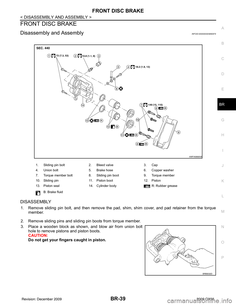
DISASSEMBLY
1. Remove sliding pin bolt, and then remove the pad, shim, shim cover, and pad retainer from the torque member.
2. Remove sliding pins and sliding pin boots from torque member.
3. Place a wooden block as shown, and blow air from union bolt hole to remove pistons and piston boots.
CAUTION:
Do not get your fingers caught in piston.
1. Sliding pin bolt 2. Bleed valve 3. Cap
4. Union bolt 5. Brake hose 6. Copper washer
7. Torque member bolt 8. Sliding pin boot 9. Torque member
10. Sliding pin 11. Piston boot 12. Piston
13. Piston seal 14. Cylinder body R: Rubber grease
B: Brake fluid
AWFIA0683GB
BRB0032D
Revision: December 20092009 QX56
Page 472 of 4171
BR-42
< DISASSEMBLY AND ASSEMBLY >
REAR DISC BRAKE
REAR DISC BRAKE
Disassembly and AssemblyINFOID:0000000005890880
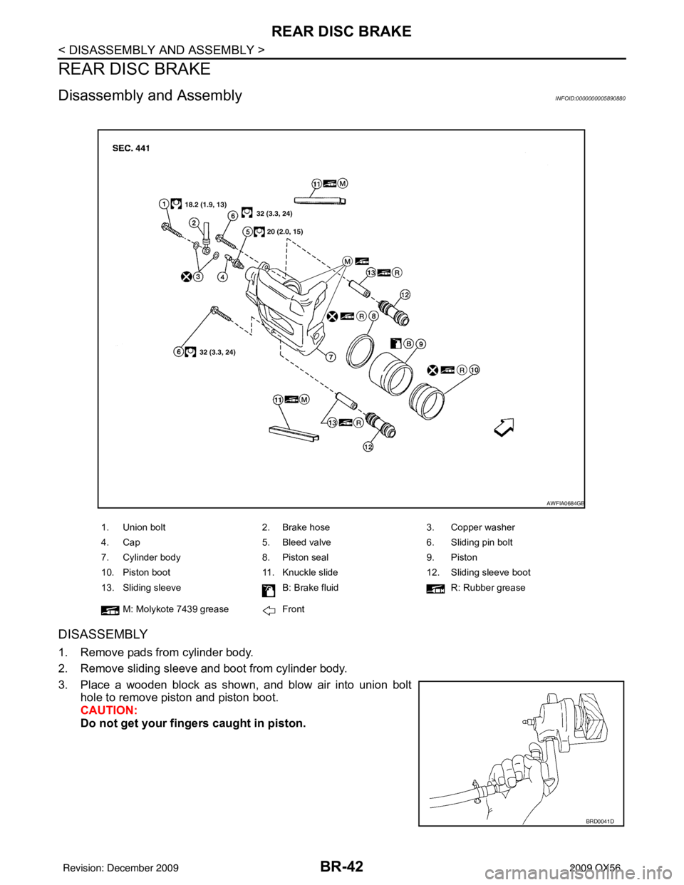
DISASSEMBLY
1. Remove pads from cylinder body.
2. Remove sliding sleeve and boot from cylinder body.
3. Place a wooden block as shown, and blow air into union bolthole to remove piston and piston boot.
CAUTION:
Do not get your fingers caught in piston.
1. Union bolt 2. Brake hose 3. Copper washer
4. Cap 5. Bleed valve 6. Sliding pin bolt
7. Cylinder body 8. Piston seal 9. Piston
10. Piston boot 11. Knuckle slide 12. Sliding sleeve boot
13. Sliding sleeve B: Brake fluidR: Rubber grease
M: Molykote 7439 grease Front
AWFIA0684GB
BRD0041D
Revision: December 20092009 QX56
Page 495 of 4171
![INFINITI QX56 2009 Factory Workshop Manual BRC-18
< FUNCTION DIAGNOSIS >[VDC/TCS/ABS]
ABS
ABS
System DiagramINFOID:0000000003772492
System DescriptionINFOID:0000000003772493
• Anti-Lock Braking System is a function that detects
wheel revolu INFINITI QX56 2009 Factory Workshop Manual BRC-18
< FUNCTION DIAGNOSIS >[VDC/TCS/ABS]
ABS
ABS
System DiagramINFOID:0000000003772492
System DescriptionINFOID:0000000003772493
• Anti-Lock Braking System is a function that detects
wheel revolu](/img/42/57031/w960_57031-494.png)
BRC-18
< FUNCTION DIAGNOSIS >[VDC/TCS/ABS]
ABS
ABS
System DiagramINFOID:0000000003772492
System DescriptionINFOID:0000000003772493
• Anti-Lock Braking System is a function that detects
wheel revolution while braking, electronically controls
braking force, and prevents wheel locking during s udden braking. It improves handling stability and maneu-
verability for avoiding obstacles.
• Electrical system diagnosis by CONSULT-III is available.
AWFIA0014GB
Revision: December 20092009 QX56
Page 587 of 4171
![INFINITI QX56 2009 Factory Workshop Manual BRC-110
< PRECAUTION >[VDC/TCS/ABS]
PRECAUTIONS
PRECAUTION
PRECAUTIONS
Precaution for Supplemental Restraint Syst
em (SRS) "AIR BAG" and "SEAT BELT
PRE-TENSIONER"
INFOID:0000000005855794
The Suppleme INFINITI QX56 2009 Factory Workshop Manual BRC-110
< PRECAUTION >[VDC/TCS/ABS]
PRECAUTIONS
PRECAUTION
PRECAUTIONS
Precaution for Supplemental Restraint Syst
em (SRS) "AIR BAG" and "SEAT BELT
PRE-TENSIONER"
INFOID:0000000005855794
The Suppleme](/img/42/57031/w960_57031-586.png)
BRC-110
< PRECAUTION >[VDC/TCS/ABS]
PRECAUTIONS
PRECAUTION
PRECAUTIONS
Precaution for Supplemental Restraint Syst
em (SRS) "AIR BAG" and "SEAT BELT
PRE-TENSIONER"
INFOID:0000000005855794
The Supplemental Restraint System such as “A IR BAG” and “SEAT BELT PRE-TENSIONER”, used along
with a front seat belt, helps to reduce the risk or severity of injury to the driver and front passenger for certain
types of collision. This system includes seat belt switch inputs and dual stage front air bag modules. The SRS
system uses the seat belt switches to determine the front air bag deployment, and may only deploy one front
air bag, depending on the severity of a collision and w hether the front occupants are belted or unbelted.
Information necessary to service the system safely is included in the SR and SB section of this Service Man-
ual.
WARNING:
• To avoid rendering the SRS inopera tive, which could increase the risk of personal injury or death in
the event of a collision which would result in air bag inflation, all maintenance must be performed by
an authorized NISSAN/INFINITI dealer.
• Improper maintenance, including in correct removal and installation of the SRS, can lead to personal
injury caused by unintent ional activation of the system. For re moval of Spiral Cable and Air Bag
Module, see the SR section.
• Do not use electrical test equipmen t on any circuit related to the SRS unless instructed to in this
Service Manual. SRS wiring harn esses can be identified by yellow and/or orange harnesses or har-
ness connectors.
PRECAUTIONS WHEN USING POWER TOOLS (AIR OR ELECTRIC) AND HAMMERS
WARNING:
• When working near the Airbag Diagnosis Sensor Unit or other Airbag System sensors with the Igni-
tion ON or engine running, DO NOT use air or electri c power tools or strike near the sensor(s) with a
hammer. Heavy vibration could activate the sensor( s) and deploy the air bag(s), possibly causing
serious injury.
• When using air or electric power tools or hammers , always switch the Ignition OFF, disconnect the
battery, and wait at least 3 minu tes before performing any service.
Precaution Necessary for Steering W heel Rotation After Battery Disconnect
INFOID:0000000005855795
NOTE:
• This Procedure is applied only to models with Intelligent Key system and NATS (NISSAN ANTI-THEFT SYS-
TEM).
• Remove and install all control units after disconnecting both battery cables with the ignition knob in the
″LOCK ″ position.
• Always use CONSULT-III to perform self-diagnosis as a part of each function inspection after finishing work.
If DTC is detected, perform trouble diagnosis according to self-diagnostic results.
For models equipped with the Intelligent Key system and NATS, an electrically controlled steering lock mech-
anism is adopted on the key cylinder.
For this reason, if the battery is disconnected or if the battery is discharged, the steering wheel will lock and
steering wheel rotation will become impossible.
If steering wheel rotation is required when battery pow er is interrupted, follow the procedure below before
starting the repair operation.
OPERATION PROCEDURE
1. Connect both battery cables. NOTE:
Supply power using jumper cables if battery is discharged.
2. Use the Intelligent Key or mechanical key to turn the ignition switch to the ″ACC ″ position. At this time, the
steering lock will be released.
3. Disconnect both battery cables. The steering lock will remain released and the steering wheel can be rotated.
4. Perform the necessary repair operation.
Revision: December 20092009 QX56
Page 588 of 4171
![INFINITI QX56 2009 Factory Workshop Manual PRECAUTIONSBRC-111
< PRECAUTION > [VDC/TCS/ABS]
C
D
E
G H
I
J
K L
M A
B
BRC
N
O P
5. When the repair work is completed, return the ignition switch to the ″LOCK ″ position before connecting
the ba INFINITI QX56 2009 Factory Workshop Manual PRECAUTIONSBRC-111
< PRECAUTION > [VDC/TCS/ABS]
C
D
E
G H
I
J
K L
M A
B
BRC
N
O P
5. When the repair work is completed, return the ignition switch to the ″LOCK ″ position before connecting
the ba](/img/42/57031/w960_57031-587.png)
PRECAUTIONSBRC-111
< PRECAUTION > [VDC/TCS/ABS]
C
D
E
G H
I
J
K L
M A
B
BRC
N
O P
5. When the repair work is completed, return the ignition switch to the ″LOCK ″ position before connecting
the battery cables. (At this time, the steering lock mechanism will engage.)
6. Perform a self-diagnosis check of al l control units using CONSULT-III.
Precaution for Brake SystemINFOID:0000000003772632
CAUTION:
• Always use recommended brake fluid. Refer to MA-12, "
Fluids and Lubricants".
• Never reuse drained brake fluid.
• Be careful not to splash brake fluid on painted areas; it may cause paint damage. If brake fluid is
splashed on painted areas, wash it away with water immediately.
• To clean or wash all parts of master cylin der and disc brake caliper, use clean brake fluid.
• Never use mineral oils such as gasoline or kerosen e. They will ruin rubber parts of the hydraulic sys-
tem.
• Use flare nut wrench when removing and installing brake
tube.
• If a brake fluid leak is found, the part must be disassembled
without fail. Then it has to be replaced with a new one if a
defect exists.
• Turn the ignition switch OFF and remove the connector of the ABS actuator and electric unit (con trol unit) or the battery ter-
minal before performing the work.
• Always torque brake lines when installing.
• Burnish the brake contact surf aces after refinishing or replac-
ing rotors, after replacing pads, or if a soft pedal occurs at
very low mileage.
Refer to BR-30, "
Brake Burnishing Procedure" (front disc brake) or BR-35, "Brake Burnishing Proce-
dure" (rear disc brake).
WARNING:
• Clean brake pads and shoes with a waste cl oth, then wipe with a dust collector.
Precaution for Brake ControlINFOID:0000000003772633
• During ABS operation, the brake pedal may vibrate lightly and a mechanical noise may be heard. This is
normal.
• Just after starting vehicle, the brake pedal may vibrate or a motor operating noise may be heard from engine
compartment. This is a normal status of operation check.
• Stopping distance may be longer than that of vehicles without ABS when vehicle drives on rough, gravel, or snow-covered (fresh, deep snow) roads.
• When an error is indicated by ABS or another warning lamp, collect all necessary information from customer (what symptoms are present under what conditions) and check for simple causes before starting diagnosis.
Besides electrical system inspection, check boos ter operation, brake fluid level, and fluid leaks.
• If incorrect tire sizes or types are installed on the vehicle or brake pads are not Genuine NISSAN parts, stop-
ping distance or steering stability may deteriorate.
• If there is a radio, antenna or related wiring near control module, ABS function may have a malfunction or
error.
• If aftermarket parts (car stereo, CD player, etc.) have been installed, check for incidents such as harness pinches, open circuits or improper wiring.
• If the following components are replaced with non-genuine components or modified, the VDC OFF indicator lamp and SLIP indicator lamp may turn on or the VDC system may not operate properly. Components
related to suspension (shock absorbers, struts, springs , bushings, etc.), tires, wheels (exclude specified
size), components related to brake system (pads, roto rs, calipers, etc.), components related to engine (muf-
fler, ECM, etc.), components related to body reinforcement (roll bar, tower bar, etc.).
• Driving with broken or excessively worn suspensi on components, tires or brake system components may
cause the VDC OFF indicator lamp and the SLIP indicator lamp to turn on, and the VDC system may not
operate properly.
• When the TCS or VDC is activated by sudden acceleration or sudden turn, some noise may occur. The noise is a result of the normal operation of the TCS and VDC.
• When driving on roads which have extreme slopes (such as mountainous roads) or high banks (such as sharp curves on a freeway), the VDC may not operate no rmally, or the VDC warning lamp and the SLIP indi-
cator lamp may turn on. This is not a problem if normal operation can be resumed after restarting the engine.
SBR686C
Revision: December 20092009 QX56
Page 598 of 4171

BRM-2
< PRECAUTION >
PRECAUTIONS
PRECAUTION
PRECAUTIONS
Precaution for Supplemental Restraint System (SRS) "AIR BAG" and "SEAT BELT
PRE-TENSIONER"
INFOID:0000000005875003
The Supplemental Restraint System such as “A IR BAG” and “SEAT BELT PRE-TENSIONER”, used along
with a front seat belt, helps to reduce the risk or severity of injury to the driver and front passenger for certain
types of collision. This system includes seat belt switch inputs and dual stage front air bag modules. The SRS
system uses the seat belt switches to determine the front air bag deployment, and may only deploy one front
air bag, depending on the severity of a collision and w hether the front occupants are belted or unbelted.
Information necessary to service the system safely is included in the SR and SB section of this Service Man-
ual.
WARNING:
• To avoid rendering the SRS inopera tive, which could increase the risk of personal injury or death in
the event of a collision which would result in air bag inflation, all maintenance must be performed by
an authorized NISSAN/INFINITI dealer.
• Improper maintenance, including in correct removal and installation of the SRS, can lead to personal
injury caused by unintent ional activation of the system. For re moval of Spiral Cable and Air Bag
Module, see the SR section.
• Do not use electrical test equipmen t on any circuit related to the SRS unless instructed to in this
Service Manual. SRS wiring harn esses can be identified by yellow and/or orange harnesses or har-
ness connectors.
PRECAUTIONS WHEN USING POWER TOOLS (AIR OR ELECTRIC) AND HAMMERS
WARNING:
• When working near the Airbag Diagnosis Sensor Unit or other Airbag System sensors with the Igni-
tion ON or engine running, DO NOT use air or electri c power tools or strike near the sensor(s) with a
hammer. Heavy vibration could activate the sensor( s) and deploy the air bag(s), possibly causing
serious injury.
• When using air or electric power tools or hammers , always switch the Ignition OFF, disconnect the
battery, and wait at least 3 minu tes before performing any service.
Precaution Necessary for Steering W heel Rotation After Battery Disconnect
INFOID:0000000005875004
NOTE:
• This Procedure is applied only to models with Intelligent Key system and NATS (NISSAN ANTI-THEFT SYS-
TEM).
• Remove and install all control units after disconnecting both battery cables with the ignition knob in the
″LOCK ″ position.
• Always use CONSULT-III to perform self-diagnosis as a part of each function inspection after finishing work.
If DTC is detected, perform trouble diagnosis according to self-diagnostic results.
For models equipped with the Intelligent Key system and NATS, an electrically controlled steering lock mech-
anism is adopted on the key cylinder.
For this reason, if the battery is disconnected or if the battery is discharged, the steering wheel will lock and
steering wheel rotation will become impossible.
If steering wheel rotation is required when battery pow er is interrupted, follow the procedure below before
starting the repair operation.
OPERATION PROCEDURE
1. Connect both battery cables. NOTE:
Supply power using jumper cables if battery is discharged.
2. Use the Intelligent Key or mechanical key to turn the ignition switch to the ″ACC ″ position. At this time, the
steering lock will be released.
3. Disconnect both battery cables. The steering lock will remain released and the steering wheel can be rotated.
4. Perform the necessary repair operation.
Revision: December 20092009 QX56
Page 599 of 4171

PRECAUTIONSBRM-3
< PRECAUTION >
C
DE
F
G H
I
J
L
M A
B
BRM
N
O P
5. When the repair work is completed, return the ignition switch to the ″LOCK ″ position before connecting
the battery cables. (At this time, the steering lock mechanism will engage.)
6. Perform a self-diagnosis check of al l control units using CONSULT-III.
Handling Precaution For PlasticsINFOID:0000000005875005
PRECAUTIONS FOR PLASTICS
1. When repairing and painting a portion of the body adjacent to plastic parts, consider their characteristics (influence of hea t and sol-
vent) and remove them if necessary or take suitable measures to protect them.
2. Plastic parts should be repaired and painted using methods suiting the materials
, characteristics.
Abbre-
viation Material name Heat resisting
temperature
°C ( °F) Resistance to gasoline and
solvents Other cautions
PE Polyethylene 60 (140)Gasoline and most solvents are
harmless if applied for a very
short time (wipe up quickly).
Flammable
ABS Acrylonitrile Butadiene Styrene 80 (176) Avoid gasoline and solvents. —
EPM/
EPDM Ethylene Propylene (Diene) co-
polymer
80 (176)Gasoline and most solvents are
harmless if applied for a very
short time (wipe up quickly). Flammable
PS Polystyrene 80 (176) Avoid solvents. Flammable
PVC Poly Vinyl Chloride 80 (176)Gasoline and most solvents are
harmless if applied for a very
short time (wipe up quickly). Poison gas is emitted
when burned.
TPO Thermoplastic Olefine 80 (176) Same as above. Flammable
AAS Acrylonitrile Acrylic Styrene 85 (185) Avoid gasoline and solvents. —
PMMA Poly Methyl Methacrylate 85 (185) Same as above. —
EVAC Ethylene Vinyl Acetate 90 (194) Avoid gasoline and solvents. —
PP Polypropylene 90 (194)Gasoline and most solvents are
harmless if applied for a very
short time (wipe up quickly). Flammable, avoid bat-
tery acid.
PUR Polyurethane 90 (194) Avoid gasoline and solvents. —
UP Unsaturated Polyester 90 (194) Same as above. Flammable
ASA Acrylonitrile Styrene Acrylate 100 (212) Same as above. Flammable
PPE Poly Phenylene Ether 110 (230) Same as above. —
TPU Thermoplastic Urethane 110 (230) Same as above. —
PBT+
PC Poly Butylene Terephthalate +
Polycarbonate
120 (248) Same as above.
Flammable
PC Polycarbonate 120 (248) Same as above. —
POM Poly Oxymethylene 120 (248) Same as above. Avoid battery acid.
PA Polyamide 140 (284) Same as above. Avoid immersing in wa-
ter.
PBT Poly Butylene Terephthalate 140 (284) Same as above. —
PAR Polyarylate 180 (356) Same as above. —
PET Polyester 180 (356) Same as above. —
PEI Polyetherimide 200 (392) Same as above. —
Revision: December 20092009 QX56
Page 602 of 4171
BRM-6
< SERVICE INFORMATION >
BODY REPAIR
SERVICE INFORMATION
BODY REPAIR
Body MountingINFOID:0000000003776117
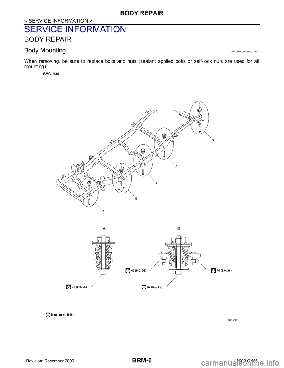
When removing, be sure to replace bolts and nuts (sealant applied bolts or self-lock nuts are used for all
mounting).
LIIA1564E
Revision: December 20092009 QX56
Page 659 of 4171
CCS-8
< BASIC INSPECTION >
INSPECTION AND ADJUSTMENT
NOTE:
If the adjustment screen does not appear on CONSULT-III 10 sec. after touching “LASER BEAM ADJUST”
screen, the following causes may be considered:
• Target is not set accurately.
• There is not enough space beside the target.
• Deformation of vehicle or inappropriate installation of sensor. Sensor may be installed out of the adjustablerange.
• The area is not suitable for the adjustment work.
• ICC sensor is not clean.
>> GO TO 2
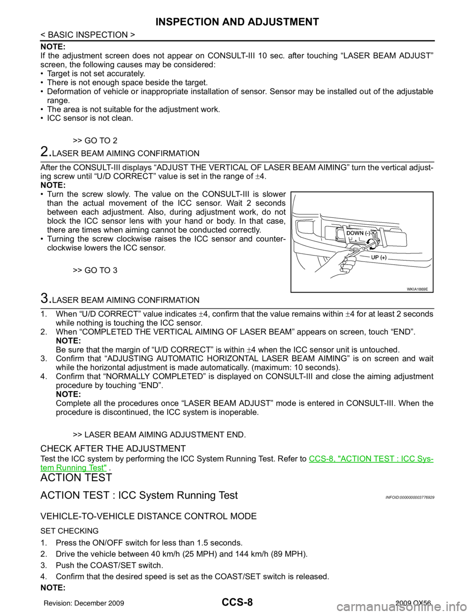
2.LASER BEAM AIMING CONFIRMATION
After the CONSULT-III displays “ADJ UST THE VERTICAL OF LASER BEAM AIMING” turn the vertical adjust-
ing screw until “U/D CORRECT” value is set in the range of ±4.
NOTE:
• Turn the screw slowly. The value on the CONSULT-III is slower
than the actual movement of the ICC sensor. Wait 2 seconds
between each adjustment. Also, during adjustment work, do not
block the ICC sensor lens with your hand or body. In that case,
there are times when aiming cannot be conducted correctly.
• Turning the screw clockwise raises the ICC sensor and counter- clockwise lowers the ICC sensor.
>> GO TO 3
3.LASER BEAM AIMING CONFIRMATION
1. When “U/D CORRECT” value indicates ±4, confirm that the value remains within ±4 for at least 2 seconds
while nothing is touching the ICC sensor.
2. When “COMPLETED THE VERTICAL AIMING OF LASER BEAM” appears on screen, touch “END”.
NOTE:
Be sure that the margin of “U/D CORRECT” is within ±4 when the ICC sensor unit is untouched.
3. Confirm that “ADJUSTING AUTOMATIC HORIZONTAL LASER BEAM AIMING” is on screen and wait
while the horizontal adjustment is made automatically. (maximum: 10 seconds).
4. Confirm that “NORMALLY COMPLETED” is displayed on CONSULT-III and close the aiming adjustment procedure by touching “END”.
NOTE:
Complete all the procedures once “LASER BEAM AD JUST” mode is entered in CONSULT-III. When the
procedure is discontinued, the ICC system is inoperable.
>> LASER BEAM AIMING ADJUSTMENT END.
CHECK AFTER THE ADJUSTMENT
Test the ICC system by performing the ICC System Running Test. Refer to CCS-8, "ACTION TEST : ICC Sys-
tem Running Test" .
ACTION TEST
ACTION TEST : ICC System Running TestINFOID:0000000003776929
VEHICLE-TO-VEHICLE DISTANCE CONTROL MODE
SET CHECKING
1. Press the ON/OFF switch for less than 1.5 seconds.
2. Drive the vehicle between 40 km/h (25 MPH) and 144 km/h (89 MPH).
3. Push the COAST/SET switch.
4. Confirm that the desired speed is set as the COAST/SET switch is released.
NOTE:
WKIA1869E
Revision: December 20092009 QX56