brake rotor INFINITI QX56 2009 Factory Service Manual
[x] Cancel search | Manufacturer: INFINITI, Model Year: 2009, Model line: QX56, Model: INFINITI QX56 2009Pages: 4171, PDF Size: 84.65 MB
Page 7 of 4171
QUICK REFERNCE CHART: QX56
2010
*2: Verify the vehicle height. If vehicle height is not within ± 10 mm (0.39 in) of the specification, perform the control unit initialization pro-
cedure.
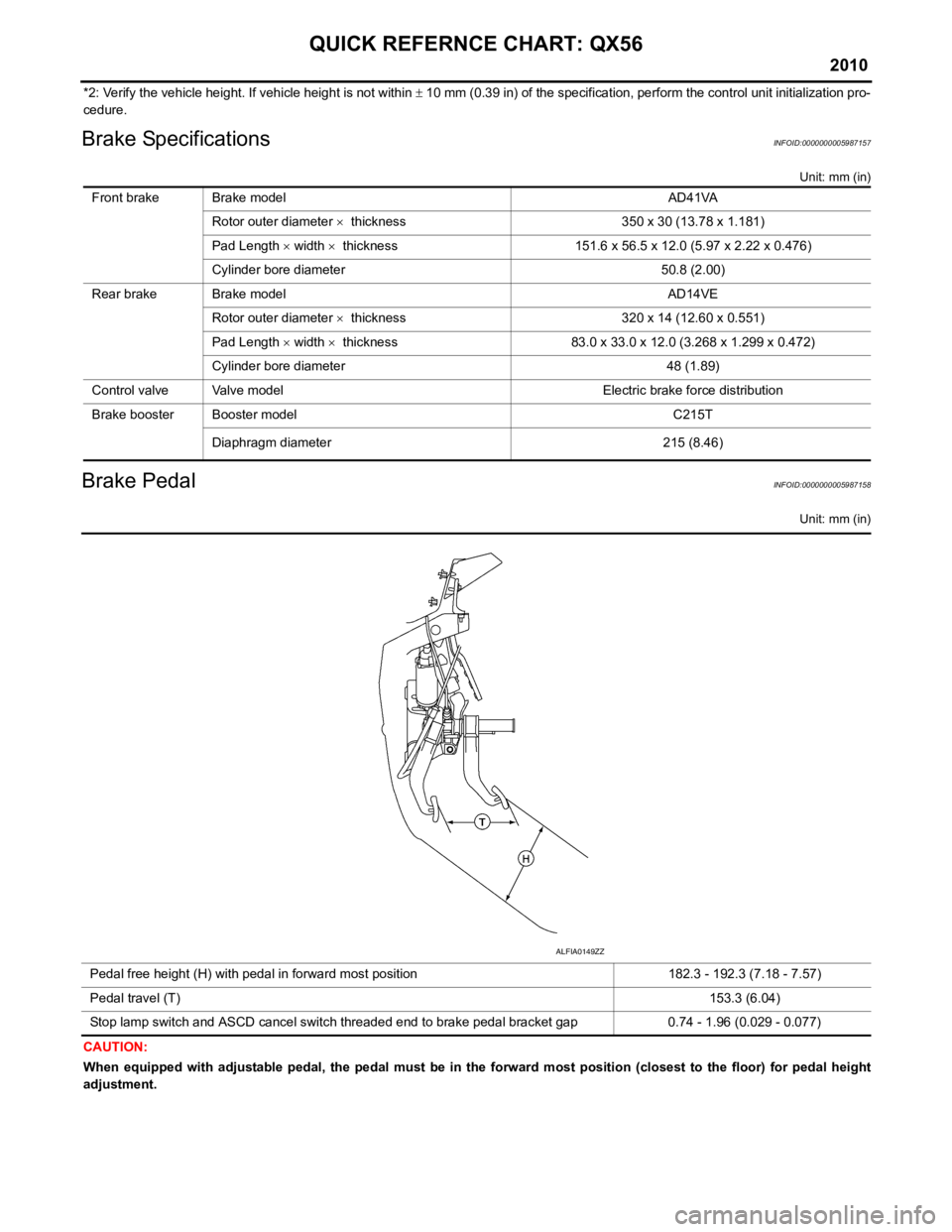
Brake SpecificationsINFOID:0000000005987157
Unit: mm (in)
Brake PedalINFOID:0000000005987158
Unit: mm (in)
CAUTION:
When equipped with adjustable pedal, the pedal must be in th e forward most position (closest to the floor) for pedal height
adjustment. Front brake Brake model AD41VA
Rotor outer diameter × thickness 350 x 30 (13.78 x 1.181)
Pad Length × width × thickness 151.6 x 56.5 x 12.0 (5.97 x 2.22 x 0.476)
Cylinder bore diameter 50.8 (2.00)
Rear brake Brake model AD14VE Rotor outer diameter × thickness 320 x 14 (12.60 x 0.551)
Pad Length × width × thickness 83.0 x 33.0 x 12.0 (3.268 x 1.299 x 0.472)
Cylinder bore diameter 48 (1.89)
Control valve Valve model Electric brake force distribution
Brake booster Booster model C215T
Diaphragm diameter 215 (8.46)
Pedal free height (H) with pedal in forward most position 182.3 - 192.3 (7.18 - 7.57)
Pedal travel (T) 153.3 (6.04)
Stop lamp switch and ASCD cancel switch threaded end to brake pedal bracket gap 0.74 - 1.96 (0.029 - 0.077)
ALFIA0149ZZ
Page 8 of 4171
2009
QUICK REFERNCE CHART: QX56
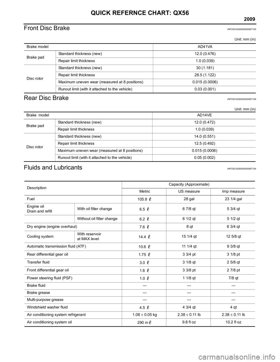
Front Disc Brake
INFOID:0000000005987155
Unit: mm (in)
Rear Disc BrakeINFOID:0000000005987156
Unit: mm (in)
Fluids and LubricantsINFOID:0000000005987154
Brake model AD41VA
Brake pad Standard thickness (new) 12.0 (0.476)
Repair limit thickness 1.0 (0.039)
Disc rotor Standard thickness (new) 30 (1.181)
Repair limit thickness 28.5 (1.122)
Maximum uneven wear (measured at 8 positions) 0.015 (0.0006)
Runout limit (with it attached to the vehicle) 0.03 (0.001)
Brake model
AD14VE
Brake pad Standard thickness (new) 12.0 (0.472)
Repair limit thickness 1.0 (0.039)
Disc rotor Standard thickness (new) 14.0 (0.551)
Repair limit thickness 12.5 (0.492)
Maximum uneven wear (measured at 8 positions) 0.015 (0.0006)
Runout limit (with it attached to the vehicle) 0.05 (0.002)
Description
Capacity (Approximate)
Metric US measure Imp measure
Fuel 105.8 28 gal 23 1/4 gal
Engine oil
Drain and refill With oil filter change
6.5 6 7/8 qt 5 3/4 qt
Without oil filter change 6.2 6 1/2 qt 5 1/2 qt
Dry engine (engine overhaul) 7.6 8 qt 6 3/4 qt
Cooling system With reservoir
at MAX level
14.4
15 1/4 qt 12 5/8 qt
Automatic transmission fluid (ATF) 10.6 11 1/4 qt 9 3/8 qt
Rear differential gear oil 1.75 3 3/4 pt 3 1/8 pt
Transfer fluid 3.0 3 1/8 qt 2 5/8 qt
Front differential gear oil 1.6 3 3/8 pt 2 7/8 pt
Power steering fluid (PSF) 1.0 1 1/8 qt 7/8 qt
Brake fluid — — —
Brake grease — — —
Multi-purpose grease — — —
Windshield washer fluid 4.5 4 3/4 qt 4 qt
Air conditioning system refrigerant 1.08 ± 0.05 kg 2.38 ± 0.11 lb 2.38 ± 0.11 lb
Air conditioning system oil 290 m9.8 fl oz 10.2 fl oz
Page 431 of 4171
BR-1
BRAKES
C
DE
G H
I
J
K L
M
SECTION BR
A
B
BR
N
O P
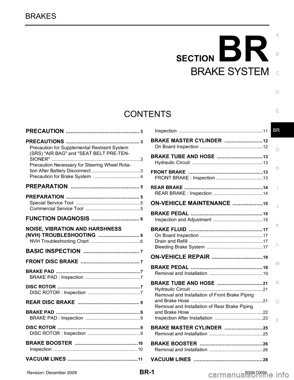
CONTENTS
BRAKE SYSTEM
PRECAUTION ....... ........................................3
PRECAUTIONS .............................................. .....3
Precaution for Supplemental Restraint System
(SRS) "AIR BAG" and "SEAT BELT PRE-TEN-
SIONER" ............................................................. ......
3
Precaution Necessary for Steering Wheel Rota-
tion After Battery Disconnect ............................... ......
3
Precaution for Brake System ....................................4
PREPARATION ............................................5
PREPARATION .............................................. .....5
Special Service Tool ........................................... ......5
Commercial Service Tool ..........................................5
FUNCTION DIAGNOSIS ...............................6
NOISE, VIBRATION AND HARSHNESS
(NVH) TROUBLESHOOTING ........................ .....
6
NVH Troubleshooting Chart ................................ ......6
BASIC INSPECTION ....................................7
FRONT DISC B RAKE .................................... .....7
BRAKE PAD .......................................................... ......7
BRAKE PAD : Inspection ..........................................7
DISC ROTOR ......................................................... ......7
DISC ROTOR : Inspection ........................................7
REAR DISC BRAKE ...................................... .....9
BRAKE PAD .......................................................... ......9
BRAKE PAD : Inspection ..........................................9
DISC ROTOR ......................................................... ......9
DISC ROTOR : Inspection ........................................9
BRAKE BOOSTER ............................................10
Inspection ............................................................ ....10
VACUUM LINES ............................................. ....11
Inspection ............................................................ ....11
BRAKE MASTER CYLINDER ..........................12
On Board Inspection ................................................12
BRAKE TUBE AND HOSE ...............................13
Hydraulic Circuit ......................................................13
FRONT BRAKE ..................................................... ....13
FRONT BRAKE : Inspection ......................... ...........13
REAR BRAKE ........................................................ ....14
REAR BRAKE : Inspection ........................ ..............14
ON-VEHICLE MAINTEN ANCE ....................15
BRAKE PEDAL .................................................15
Inspection and Adjustment .................................. ....15
BRAKE FLUID ..................................................17
On Board Inspection ............................................ ....17
Drain and Refill ........................................................17
Bleeding Brake System ...........................................17
ON-VEHICLE REPAIR .................................19
BRAKE PEDAL .................................................19
Removal and Installation ..................................... ....19
BRAKE TUBE AND HOSE ...............................21
Hydraulic Circuit ......................................................21
Removal and Installation of Front Brake Piping
and Brake Hose .......................................................
21
Removal and Installation of Rear Brake Piping
and Brake Hose .......................................................
22
Inspection After Installation .....................................23
BRAKE MASTER CYLINDER ..........................25
Removal and Installation .........................................25
BRAKE BOOSTER ...........................................26
Removal and Installation ..................................... ....26
VACUUM LINES ...............................................28
Revision: December 20092009 QX56
Page 432 of 4171

BR-2
Removal and Installation ........................................28
FRONT DISC BRAKE ........................................29
Exploded View of Brake Pads ............................. ...29
Removal and Installation of Brake Pads .................29
Brake Burnishing Procedure ...................................30
Exploded View of Brake Caliper .............................31
Removal and Installation of Brake Caliper and Ro-
tor ...........................................................................
31
REAR DISC BRAKE ..........................................34
Exploded View of Brake Pads ............................. ...34
Removal and Installation of Brake Pad ..................34
Brake Burnishing Procedure ...................................35
Exploded View of Brake Caliper .............................35
Removal and Installation of Brake Caliper and
Disc Rotor ............................................................ ...
36
DISASSEMBLY AND ASSEMBLY .............37
BRAKE MASTER CYLINDER ........................ ...37
Disassembly and Assembly ................................. ...37
FRONT DISC BRAKE .......................................39
Disassembly and Assembly ................................. ...39
REAR DISC BRAKE ....................................... ...42
Disassembly and Assembly ................................. ...42
SERVICE DATA AND SPECIFICATIONS
(SDS) .......... ................................. ...............
45
SERVICE DATA AND SPECIFICATIONS
(SDS) .............................................................. ...
45
General Specification ........................................... ...45
Brake Pedal ............................................................45
Brake Booster .........................................................46
Check Valve ............................................................46
Front Disc Brake .....................................................46
Rear Disc Brake ......................................................46
Revision: December 20092009 QX56
Page 434 of 4171
BR-4
< PRECAUTION >
PRECAUTIONS
5. When the repair work is completed, return the ignition switch to the ″LOCK ″ position before connecting
the battery cables. (At this time, the steering lock mechanism will engage.)
6. Perform a self-diagnosis check of a ll control units using CONSULT-III.
Precaution for Brake SystemINFOID:0000000003772409
• Always use recommended brake fluid. Refer to MA-12, "Fluids and Lubricants".
• Do not reuse drained brake fluid.
• Be careful not to splash brake fluid on painted areas.
• To clean or wash all parts of master cylinder, disc brake caliper and wheel cylinder, use clean brake fluid.
• Do not use mineral oils such as gasoline or kerosene. They will ruin rubber parts of the hydraulic system.
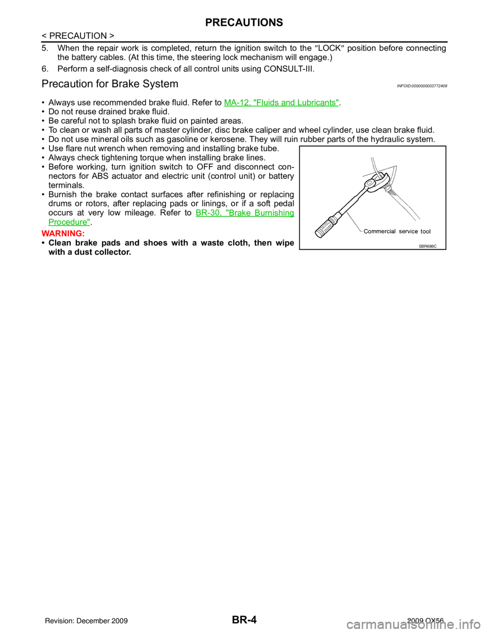
• Use flare nut wrench when removing and installing brake tube.
• Always check tightening torque when installing brake lines.
• Before working, turn ignition switch to OFF and disconnect con- nectors for ABS actuator and electric unit (control unit) or battery
terminals.
• Burnish the brake contact surfaces after refinishing or replacing drums or rotors, after replacing pads or linings, or if a soft pedal
occurs at very low mileage. Refer to BR-30, "
Brake Burnishing
Procedure".
WARNING:
• Clean brake pads and shoes wi th a waste cloth, then wipe
with a dust collector.
SBR686C
Revision: December 20092009 QX56
Page 435 of 4171
PREPARATIONBR-5
< PREPARATION >
C
DE
G H
I
J
K L
M A
B
BR
N
O P
PREPARATION
PREPARATION
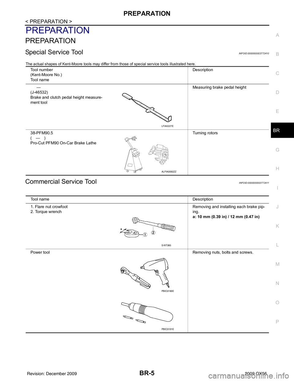
Special Service ToolINFOID:0000000003772410
The actual shapes of Kent-Moore tools may differ from those of special service tools illustrated here.
Commercial Service ToolINFOID:0000000003772411
Tool number
(Kent-Moore No.)
Tool name Description
—
(J-46532)
Brake and clutch pedal height measure-
ment tool Measuring brake pedal height
38-PFM90.5
(—)
Pro-Cut PFM90 On-Car Brake Lathe Turning rotors
LFIA0227E
ALFIA0092ZZ
Tool name
Description
1. Flare nut crowfoot
2. Torque wrench Removing and installing each brake pip-
ing.
a: 10 mm (0.39 in) / 12 mm (0.47 in)
Power tool Removing nuts, bolts and screws.
S-NT360
PBIC0190E
PBIC0191E
Revision: December 20092009 QX56
Page 437 of 4171
FRONT DISC BRAKEBR-7
< BASIC INSPECTION >
C
DE
G H
I
J
K L
M A
B
BR
N
O P
BASIC INSPECTION
FRONT DISC BRAKE
BRAKE PAD
BRAKE PAD : InspectionINFOID:0000000003772414
PA D W E A R
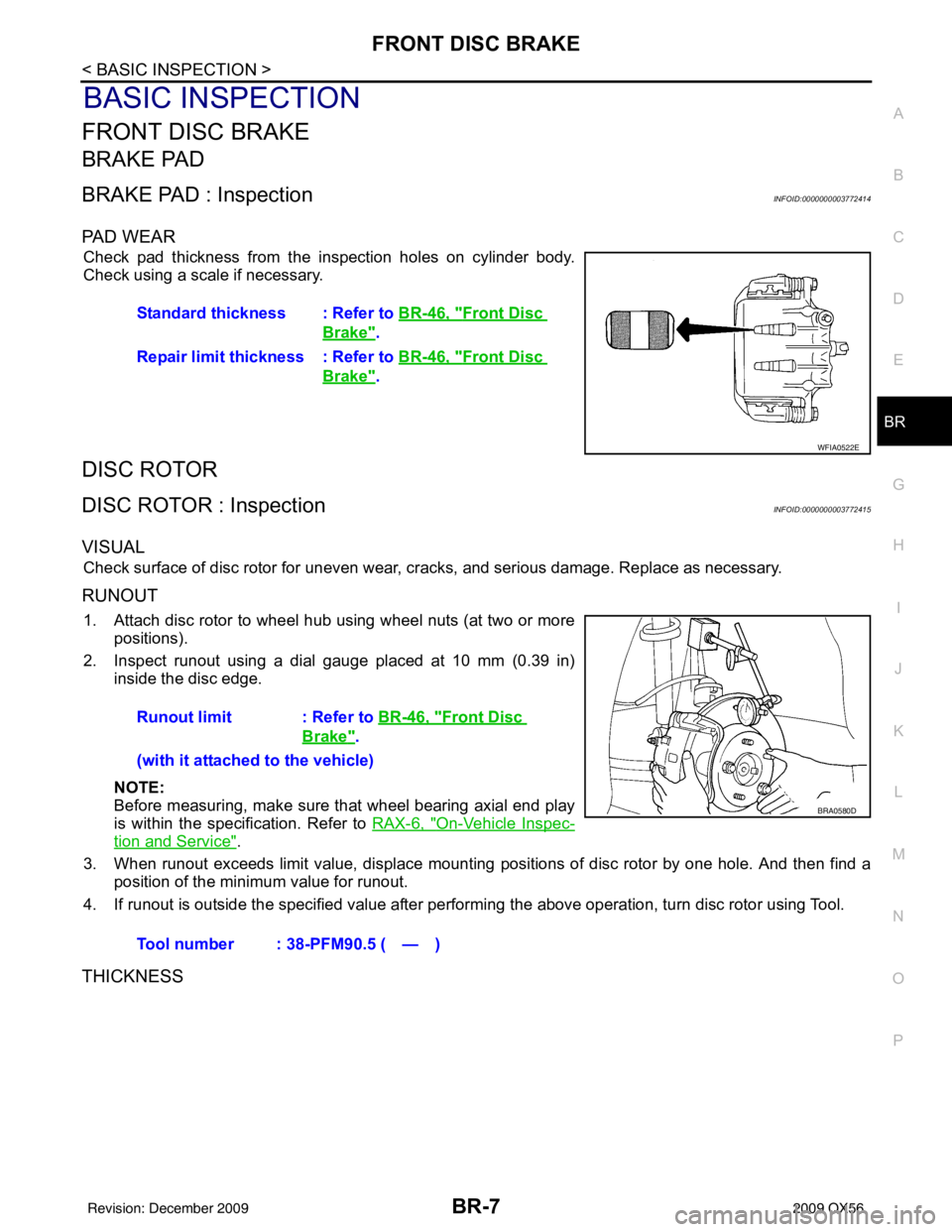
Check pad thickness from the inspection holes on cylinder body.
Check using a scale if necessary.
DISC ROTOR
DISC ROTOR : InspectionINFOID:0000000003772415
VISUAL
Check surface of disc rotor for uneven wear, cracks, and serious damage. Replace as necessary.
RUNOUT
1. Attach disc rotor to wheel hub using wheel nuts (at two or more positions).
2. Inspect runout using a dial gauge placed at 10 mm (0.39 in) inside the disc edge.
NOTE:
Before measuring, make sure that wheel bearing axial end play
is within the specification. Refer to RAX-6, "
On-Vehicle Inspec-
tion and Service".
3. When runout exceeds limit value, displace mounting positions of disc rotor by one hole. And then find a position of the minimum value for runout.
4. If runout is outside the specified value after performing the above operation, turn disc rotor using Tool.
THICKNESS
Standard thickness : Refer to BR-46, "Front Disc
Brake".
Repair limit thickness : Refer to BR-46, "
Front Disc
Brake".
WFIA0522E
Runout limit : Refer to BR-46, "Front Disc
Brake".
(with it attached to the vehicle)
Tool number : 38-PFM90.5 ( — )
BRA0580D
Revision: December 20092009 QX56
Page 438 of 4171

BR-8
< BASIC INSPECTION >
FRONT DISC BRAKE
Check thickness of the disc rotor using a micrometer. Replace disc
rotor if thickness is less than the wear limit.Standard thickness : Refer to BR-46, "
Front
Disc Brake".
Repair limit thickness : Refer to BR-46, "
Front
Disc Brake".
Thickness variation
(Measured at 8 positions) : Refer to
BR-46, "
Front
Disc Brake".
SBR020B
Revision: December 20092009 QX56
Page 439 of 4171
REAR DISC BRAKEBR-9
< BASIC INSPECTION >
C
DE
G H
I
J
K L
M A
B
BR
N
O P
REAR DISC BRAKE
BRAKE PAD
BRAKE PAD : InspectionINFOID:0000000003772417
PA D W E A R
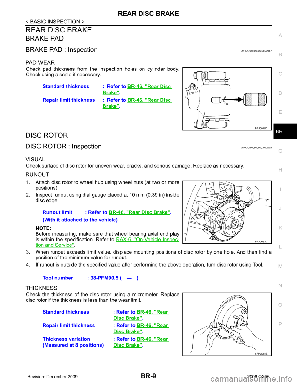
Check pad thickness from the inspection holes on cylinder body.
Check using a scale if necessary.
DISC ROTOR
DISC ROTOR : InspectionINFOID:0000000003772418
VISUAL
Check surface of disc rotor for uneven wear, cracks, and serious damage. Replace as necessary.
RUNOUT
1. Attach disc rotor to wheel hub using wheel nuts (at two or more positions).
2. Inspect runout using dial gauge placed at 10 mm (0.39 in) inside disc edge.
NOTE:
Before measuring, make sure that wheel bearing axial end play
is within the specification. Refer to RAX-6, "
On-Vehicle Inspec-
tion and Service".
3. When runout exceeds limit value, displace mounting positions of disc rotor by one hole. And then find a position of the minimum value for runout.
4. If runout is outside the specified value after performing the above operation, turn disc rotor using Tool.
THICKNESS
Check the thickness of the disc rotor using a micrometer. Replace
disc rotor if the thickness is less than the wear limit. Standard thickness : Refer to
BR-46, "
Rear Disc
Brake".
Repair limit thickness : Refer to BR-46, "
Rear Disc
Brake".
BRA0010D
Runout limit : Refer to BR-46, "Rear Disc Brake".
(With it attached to the vehicle)
Tool number : 38-PFM90.5 ( — )
BRA0697D
Standard thickness : Refer to BR-46, "Rear
Disc Brake".
Repair limit thickness : Refer to BR-46, "
Rear
Disc Brake".
Thickness variation
(Measured at 8 positions) : Refer to
BR-46, "
Rear
Disc Brake".
SFIA2284E
Revision: December 20092009 QX56
Page 459 of 4171
FRONT DISC BRAKEBR-29
< ON-VEHICLE REPAIR >
C
DE
G H
I
J
K L
M A
B
BR
N
O P
FRONT DISC BRAKE
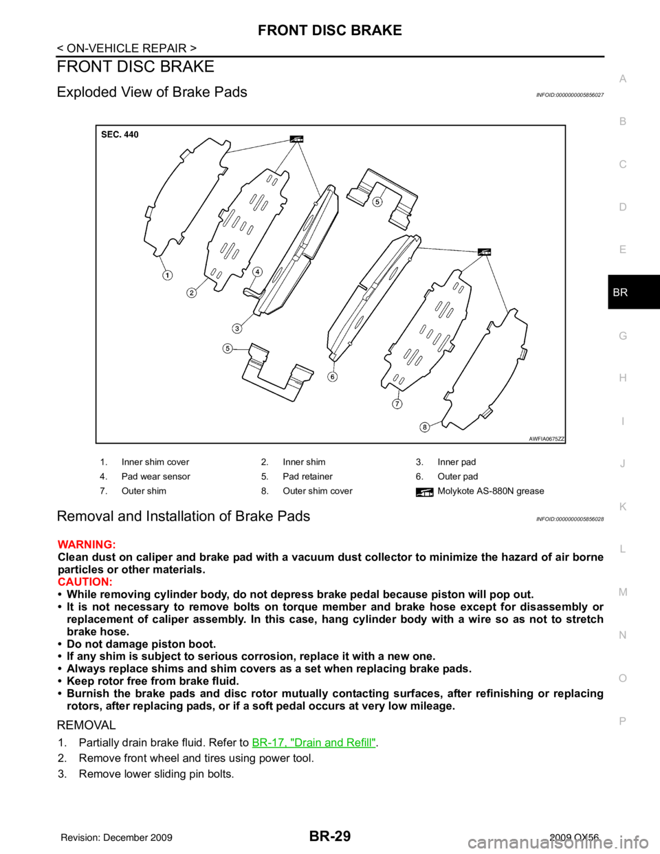
Exploded View of Brake PadsINFOID:0000000005856027
Removal and Installation of Brake PadsINFOID:0000000005856028
WARNING:
Clean dust on caliper and brake pad with a vacuum dust collector to minimize the hazard of air borne
particles or other materials.
CAUTION:
• While removing cylinder bod y, do not depress brake pedal because piston will pop out.
• It is not necessary to remove bolts on torque member and brake hose except for disassembly or replacement of caliper assembly. In this case, hang cylinder body with a wire so as not to stretch
brake hose.
• Do not damage piston boot.
• If any shim is subject to serious corrosion, replace it with a new one.
• Always replace shims and shim covers as a set when replacing brake pads.
• Keep rotor free from brake fluid.
• Burnish the brake pads and disc rotor mutually contacting surfaces, after refinishing or replacing rotors, after replacing pads, or if a so ft pedal occurs at very low mileage.
REMOVAL
1. Partially drain brake fluid. Refer to BR-17, "Drain and Refill".
2. Remove front wheel and tires using power tool.
3. Remove lower sliding pin bolts.
1. Inner shim cover 2. Inner shim3. Inner pad
4. Pad wear sensor 5. Pad retainer6. Outer pad
7. Outer shim 8. Outer shim cover Molykote AS-880N grease
AWFIA0675ZZ
Revision: December 20092009 QX56