Oil INFINITI QX56 2010 Factory Service Manual
[x] Cancel search | Manufacturer: INFINITI, Model Year: 2010, Model line: QX56, Model: INFINITI QX56 2010Pages: 4210, PDF Size: 81.91 MB
Page 1958 of 4210

HOW TO SELECT PISTON AND BEARINGEM-107
< DISASSEMBLY AND ASSEMBLY >
C
DE
F
G H
I
J
K L
M A
EM
NP
O
Use Undersize Bearing Usage Guide
• Use undersize (US) bearing when the oil clearance with
standard size main bearing is not within specifica-
tion.
• When using undersize (US) bearing, measure the inside di ameter of the bearing installed and grind the jour-
nal until the oil clearance falls within specification.
Bearing undersize table
Unit: mm (in)
CAUTION:
Do not damage fillet R when grinding crankshaft journal in
order to use undersized bearing (All journals).
01 UPR
2.483 - 2.486 (0.0978 - 0.0979) Black
Grade and color are different
for upper and lower bearings.
LWR
2.486 - 2.489 (0.0979 - 0.0980) Brown
12 UPR
2.486 - 2.489 (0.0979 - 0.0980) Brown
LWR 2.489 - 2.492 (0.0980 - 0.0981) Green
23 UPR
2.489 - 2.492 (0.0980 - 0.0981) Green
LWR 2.492 - 2.495 (0.0981 - 0.0982) Yellow
34 UPR
2.492 - 2.495 (0.0981 - 0.0982) Yellow
LWR 2.495 - 2.498 (0.0982 - 0.0983) Blue
45 UPR
2.495 - 2.498 (0.0982 - 0.0983) Blue
LWR 2.498 - 2.501 (0.0983 - 0.0985) Pink
56 UPR
2.498 - 2.501 (0.0983 - 0.0985) Pink
LWR 2.501 - 2.504 (0.0985 - 0.0986) Purple
67 UPR
2.501 - 2.504 (0.0985 - 0.0986) Purple
LWR 2.504 - 2.507 (0.0986 - 0.0987) White
78 UPR
2.504 - 2.507 (0.0986 - 0.0987) White
LWR 2.507 - 2.510 (0.0987 - 0.0988) Red
UndersizeThickness
0.25 (0.0098) 2.618 - 2.626 (0.1031 - 0.1034)
Fillet R : 1.5 - 1.7 mm (0.059 - 0.067 in)
PBIC0111E
Revision: April 20092010 QX56
Page 1959 of 4210

EM-108
< SERVICE DATA AND SPECIFICATIONS (SDS)
SERVICE DATA AND SPECIFICATIONS (SDS)
SERVICE DATA AND SPECIFICATIONS (SDS)
SERVICE DATA AND SPECIFICATIONS (SDS)
Standard and LimitINFOID:0000000005149018
GENERAL SPECIFICATIONS
DRIVE BELTS
EXHAUST MANIFOLD
Cylinder arrangementV- 8
Displacement cm
3(in3) 5,552 (338.80)
Bore and stroke mm (in) 98 x 92 (3.86 x 3.62)
Valve arrangement DOHC
Firing order 1-8-7-3-6-5-4-2
Number of piston rings Compression
2
Oil 1
Number of main bearings 5
Compression ratio 9.8:1
Compression pressure
kPa (kg/cm
2, psi)/rpm Standard 1,520 (15.5, 220)/200
Minimum
1,324 (13.5, 192)/200
Differential limit between cylinders 98 (1.0, 14)/200
Cylinder number
Valve timing Unit: degree
abcde f
244 ° 232° -8° 60° 10° 54°
SEM957C
PBIC0187E
Tension of drive belts Auto adjustment by auto tensioner
Revision: April 20092010 QX56
Page 1965 of 4210

EM-114
< SERVICE DATA AND SPECIFICATIONS (SDS)
SERVICE DATA AND SPECIFICATIONS (SDS)
Unit: mm (in)
*: Always check with the Parts Department for the latest parts information
Piston Ring
Unit: mm (in)
Piston Pin
Unit: mm (in)
*: Always check with the Parts Department for the latest parts information
CONNECTING ROD
Unit: mm (in)
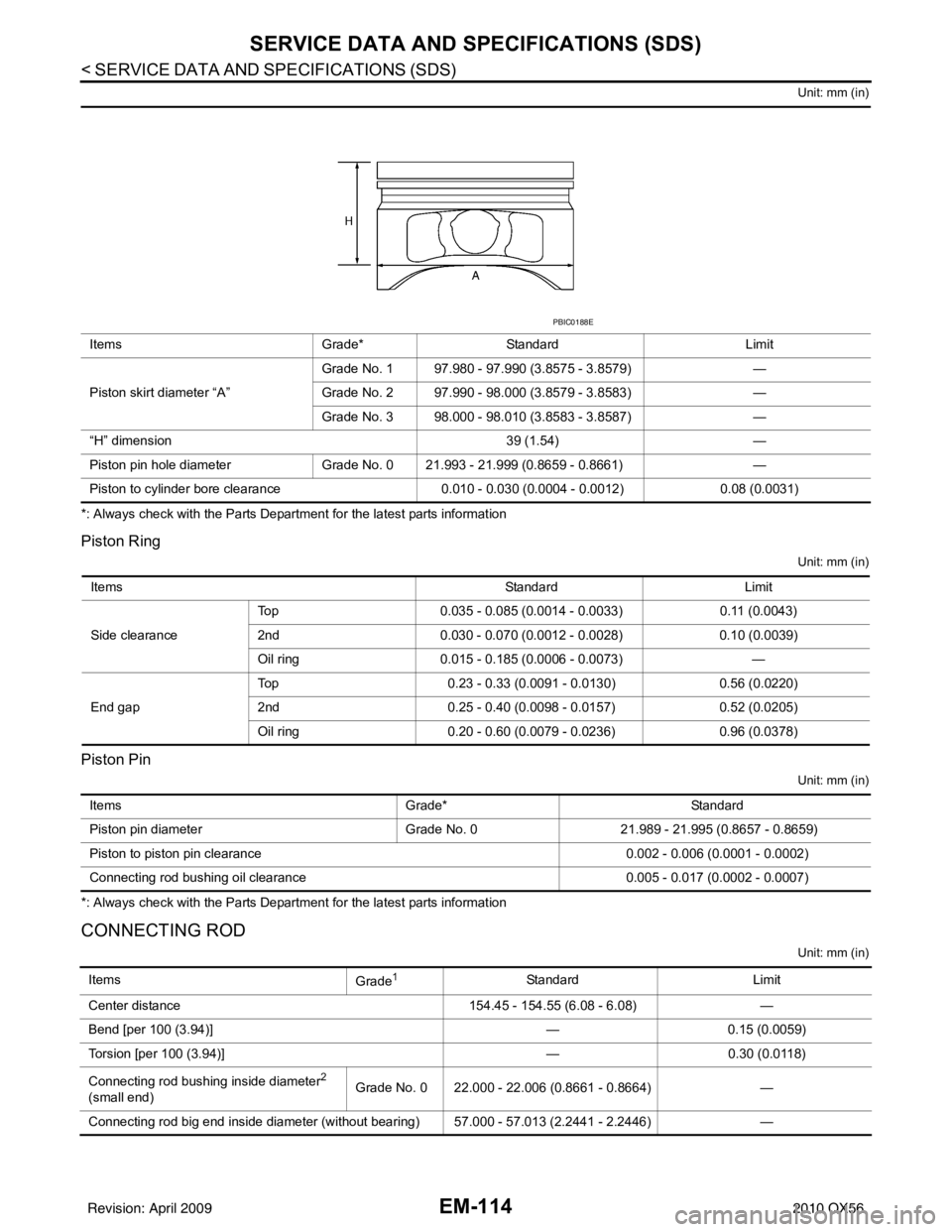
ItemsGrade*Standard Limit
Piston skirt diameter “A” Grade No. 1 97.980 - 97.990 (3.8575 - 3.8579)
—
Grade No. 2 97.990 - 98.000 (3.8579 - 3.8583) —
Grade No. 3 98.000 - 98.010 (3.8583 - 3.8587) —
“H” dimension 39 (1.54)—
Piston pin hole diameter Grade No. 0 21.993 - 21.999 (0.8659 - 0.8661) —
Piston to cylinder bore clearance 0.010 - 0.030 (0.0004 - 0.0012)0.08 (0.0031)
PBIC0188E
Items StandardLimit
Side clearance Top
0.035 - 0.085 (0.0014 - 0.0033) 0.11 (0.0043)
2nd 0.030 - 0.070 (0.0012 - 0.0028) 0.10 (0.0039)
Oil ring 0.015 - 0.185 (0.0006 - 0.0073) —
End gap Top
0.23 - 0.33 (0.0091 - 0.0130) 0.56 (0.0220)
2nd 0.25 - 0.40 (0.0098 - 0.0157) 0.52 (0.0205)
Oil ring 0.20 - 0.60 (0.0079 - 0.0236) 0.96 (0.0378)
Items Grade*Standard
Piston pin diameter Grade No. 0 21.989 - 21.995 (0.8657 - 0.8659)
Piston to piston pin clearance 0.002 - 0.006 (0.0001 - 0.0002)
Connecting rod bushing oil clearance 0.005 - 0.017 (0.0002 - 0.0007)
Items
Grade1StandardLimit
Center distance 154.45 - 154.55 (6.08 - 6.08)—
Bend [per 100 (3.94)] —0.15 (0.0059)
Torsion [per 100 (3.94)] —0.30 (0.0118)
Connecting rod bushing inside diameter
2
(small end) Grade No. 0 22.000 - 22.006 (0.8661 - 0.8664)
—
Connecting rod big end inside diameter (without bearing) 57.000 - 57.013 (2.2441 - 2.2446) —
Revision: April 20092010 QX56
Page 1968 of 4210

SERVICE DATA AND SPECIFICATIONS (SDS)EM-117
< SERVICE DATA AND SPECIFICATIONS (SDS)
C
DE
F
G H
I
J
K L
M A
EM
NP
O
*: Always check with the Parts Department for the latest parts information
Undersize
Unit: mm (in)
Main Bearing Oil Clearance
Unit: mm (in)
Connecting Rod Bearing
*: Always check with the Parts Department for the latest parts information
Undersize
0
—2.483 - 2.486 (0.0978 - 0.0979) Black
Grade is the same for upper
and lower bearings
1
—2.486 - 2.489 (0.0979 - 0.0980) Brown
2 —2.489 - 2.492 (0.0980 - 0.0981) Green
3 —2.492 - 2.495 (0.0981 - 0.0982) Yellow
4 —2.495 - 2.498 (0.0982 - 0.0983) Blue
5 —2.498 - 2.501 (0.0983 - 0.0985) Pink
6 —2.501 - 2.504 (0.0985 - 0.0986) Purple
7 —2.504 - 2.507 (0.0986 - 0.0987) White
8 —2.507 - 2.510 (0.0987 - 0.0988) Red
01 UPR
2.483 - 2.486 (0.0978 - 0.0979) Black
Grade is different for upper and
lower bearings.
LWR
2.486 - 2.489 (0.0979 - 0.0980) Brown
12 UPR
2.486 - 2.489 (0.0979 - 0.0980) Brown
LWR 2.489 - 2.492 (0.0980 - 0.0981) Green
23 UPR
2.489 - 2.492 (0.0980 - 0.0981) Green
LWR 2.492 - 2.495 (0.0981 - 0.0982) Yellow
34 UPR
2.492 - 2.495 (0.0981 - 0.0982) Yellow
LWR 2.495 - 2.498 (0.0982 - 0.0983) Blue
45 UPR
2.495 - 2.498 (0.0982 - 0.0983) Blue
LWR 2.498 - 2.501 (0.0983 - 0.0985) Pink
56 UPR
2.498 - 2.501 (0.0983 - 0.0985) Pink
LWR 2.501 - 2.504 (0.0985 - 0.0986) Purple
67 UPR
2.501 - 2.504 (0.0985 - 0.0986) Purple
LWR 2.504 - 2.507 (0.0986 - 0.0987) White
78 UPR
2.504 - 2.507 (0.0986 - 0.0987) White
LWR 2.507 - 2.510 (0.0987 - 0.0988) Red
UndersizeThickness Main journal diameter
0.25 (0.0098) 2.618 - 2.626 (0.1031 - 0.1034) Grind so that bearing clearance is the specified value.
Items StandardLimit
Main bearing oil clearance No.1 and 5
0.001 - 0.011 (0.00004 - 0.0004) 0.021 (0.0008)
No.2, 3 and 4 0.007 - 0.017 (0.0003 - 0.0007) 0.027 (0.0011)
Grade number*Thickness “T” mm (in) Identification color (mark)
0 1.500 - 1.503 (0.0591 - 0.0592) Black
1 1.503 - 1.506 (0.0592 - 0.0593) Brown
2 1.506 - 1.509 (0.0593 - 0.0594) Green
3 1.509 - 1.512 (0.0594 - 0.0595) Yellow
Revision: April 20092010 QX56
Page 1969 of 4210

EM-118
< SERVICE DATA AND SPECIFICATIONS (SDS)
SERVICE DATA AND SPECIFICATIONS (SDS)
Unit: mm (in)
Connecting Rod Bearing Oil Clearance
Unit: mm (in)
UndersizeThicknessCrank pin journal diameter “Dp”
0.25 (0.0098) 1.627 - 1.635 (0.0641 - 0.0644) Grind so that bearing clearance is the specified value.
Items StandardLimit
Connecting rod bearing oil clearance 0.020 - 0.039 (0.0008 - 0.0015) 0.055 (0.0022)
Revision: April 20092010 QX56
Page 1983 of 4210

HEADLAMPEXL-7
< FUNCTION DIAGNOSIS >
C
DE
F
G H
I
J
K
M A
B
EXL
N
O P
FUNCTION DIAGNOSIS
HEADLAMP
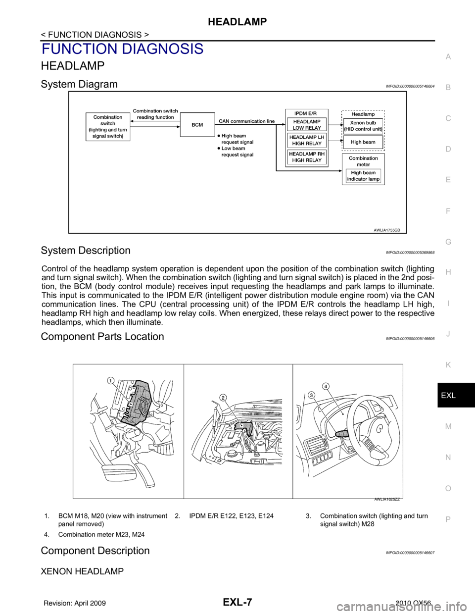
System DiagramINFOID:0000000005146604
System DescriptionINFOID:0000000005369868
Control of the headlamp system operation is dependent upon t he position of the combination switch (lighting
and turn signal switch). When the combination switch (lighting and turn signal switch) is placed in the 2nd posi-
tion, the BCM (body control module) receives input requesting the headlamps and park lamps to illuminate.
This input is communicated to the IPDM E/R (intelligent power distribution module engine room) via the CAN
communication lines. The CPU (central processing unit) of the IPDM E/R controls the headlamp LH high,
headlamp RH high and headlamp low relay coils. When energiz ed, these relays direct power to the respective
headlamps, which then illuminate.
Component Parts LocationINFOID:0000000005146606
Component DescriptionINFOID:0000000005146607
XENON HEADLAMP
AWLIA1755GB
1. BCM M18, M20 (view with instrument
panel removed) 2. IPDM E/R E122, E123, E124 3. Combination switch (lighting and turn
signal switch) M28
4. Combination meter M23, M24
AWLIA1625ZZ
Revision: April 20092010 QX56
Page 1984 of 4210

EXL-8
< FUNCTION DIAGNOSIS >
HEADLAMP
A Xenon type headlamp is adapted to the low beam headlamps. Xenon bulbs do not use a filament. Instead,
they produce light when a high voltage current is pa ssed between two tungsten electrodes through a mixture
of Xenon (an inert gas) and certain other metal halides. In addition to added lighting power, electronic control
of the power supply gives the headlamps stable quality and tone color. Following are some of the advantages
of the Xenon type headlamp.
• The light produced by the headlamps is a white color comparable to sunlight that is easy on the eyes.
• Light output is nearly double that of halogen headlamps, affording increased area of illumination.
• The light features a high relative spectral distribution at wavelengths to which the human eye is most sensi- tive. This means that even in the rain, more light is reflected back from the road surface toward the vehicle,
for added visibility.
• Power consumption is approximately 25 percent less than halogen headlamps, reducing battery load.
HIGH BEAM OPERATION/FLASH-TO-PASS OPERATION
With the combination switch (lighting and turn signal switch) in the 2ND position and placed in HIGH position,
the BCM receives input requesting the headlamp high beams to illuminate. The flash to pass feature can be
used any time and also sends a signal to the BCM. This input is communicated to the IPDM E/R via the CAN
communication lines. The CPU of the combination meter c ontrols the ON/OFF status off the HIGH BEAM indi-
cator. The CPU of the IPDM E/R controls the headlamp high relay coil which supplies power to the high beam
headlamps.
The combination meter receives a high beam request signal (ON) via the CAN communication lines and turns
the high beam indicator lamp ON.
EXTERIOR LAMP BATTERY SAVER CONTROL
With the combination switch (lighting and turn signal switch) in the 2nd position and the ignition switch is
turned from ON or ACC to OFF, the battery saver feature is activated.
Under this condition, the headlamps remain illuminated for 5 minutes unless the lighting switch position is
changed. If the lighting switch position is changed, then the headlamps are turned off.
This setting can be changed by CONSULT-III. Refer to BCS-22, "
HEADLAMP : CONSULT-III Function (BCM -
HEAD LAMP)".
Revision: April 20092010 QX56
Page 1990 of 4210

EXL-14
< FUNCTION DIAGNOSIS >
FRONT FOG LAMP
FRONT FOG LAMP
System DiagramINFOID:0000000005369879
System DescriptionINFOID:0000000005369880
The front fog lamps are activated with the combination switch (lighting and turn signal switch). The combina-
tion switch (lighting and turn signal switch) signal to the BCM is monitored with the BCM combination switch
reading function. When the fog lamps are turned ON wit h the combination switch (lighting and turn signal
switch), the BCM sends a front fog lamp request signal via CAN communication lines to the IPDM E/R. The
IPDM E/R grounds the front fog lamp relay coil to activate the front fog lamps.
Component Parts LocationINFOID:0000000005146622
Component DescriptionINFOID:0000000005369881
FRONT FOG LAMP OPERATION
When the combination switch (lighting and turn signal switch) is in front fog lamp ON position and also in 1ST
or 2ND position or AUTO position (headlamp is ON), the BCM detects FR FOG ON and the HEAD LAMP1, 2
ON or the AUTO LIGHT ON. The BCM sends a front fog lamp request ON signal via the CAN communication
lines to the IPDM E/R. The IPDM E/R then turns ON t he front fog lamp relay sending power to the front fog
lamps.
AWLIA1719GB
1. BCM M18, M20 (view with instrument
panel removed) 2. IPDM E/R E122, E123, E124 3. Combination switch (lighting and turn
signal switch) M28
AWNIA0509ZZ
Revision: April 20092010 QX56
Page 1998 of 4210

EXL-22
< FUNCTION DIAGNOSIS >
DIAGNOSIS SYSTEM (IPDM E/R)
DIAGNOSIS SYSTEM (IPDM E/R)
Diagnosis DescriptionINFOID:0000000005369886
AUTO ACTIVE TEST
Description
In auto active test mode, the IPDM E/R sends a drive signal to the follo wing systems to check their operation.
• Oil pressure low/coolant pressure high warning indicator
• Oil pressure gauge
• Rear window defogger
• Front wipers
• Tail, license and parking lamps
• Front fog lamps
• Headlamps (Hi, Lo)
• A/C compressor (magnetic clutch)
• Cooling fan
Operation Procedure
1. Close the hood and front door RH, and lift the wiper a rms from the windshield (to prevent windshield dam-
age due to wiper operation).
NOTE:
When auto active test is performed with hood opened, sprinkle water on windshield before hand.
2. Turn ignition switch OFF.
3. Turn the ignition switch ON and, within 20 seconds, press the front door switch LH 10 times. Then turn the ignition switch OFF.
4. Turn the ignition switch ON within 10 seconds. Af ter that the horn sounds once and the auto active test
starts.
5. After a series of the following operations is repeated 3 times, auto active test is completed.
NOTE:
When auto active test mode has to be cancelled halfway through test, turn ignition switch OFF.
CAUTION:
• If auto active test mode cannot be actuated, check door switch system. Refer to DLK-71, "
Descrip-
tion".
• Do not start the engine.
Inspection in Auto Active Test Mode
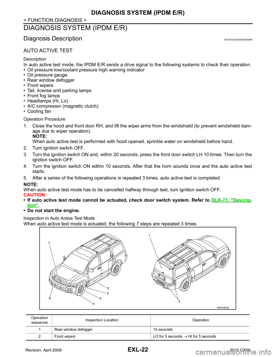
When auto active test mode is actuated, the following 7 steps are repeated 3 times.
Operation
sequence Inspection Location
Operation
1 Rear window defogger 10 seconds
2 Front wipers LO for 5 seconds → HI for 5 seconds
WKIA4655E
Revision: April 20092010 QX56
Page 1999 of 4210

DIAGNOSIS SYSTEM (IPDM E/R)EXL-23
< FUNCTION DIAGNOSIS >
C
DE
F
G H
I
J
K
M A
B
EXL
N
O P
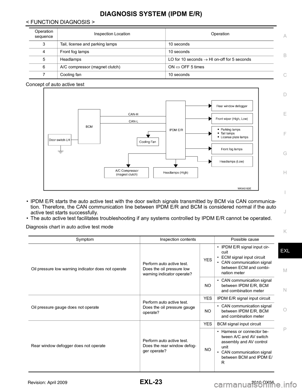
Concept of auto active test
• IPDM E/R starts the auto active test with the door
switch signals transmitted by BCM via CAN communica-
tion. Therefore, the CAN communication line between IPDM E/R and BCM is considered normal if the auto
active test starts successfully.
• The auto active test facilitates troubleshooting if any systems controlled by IPDM E/R cannot be operated.
Diagnosis chart in auto active test mode
3 Tail, license and parking lamps 10 seconds
4 Front fog lamps 10 seconds
5 Headlamps LO for 10 seconds → HI on-off for 5 seconds
6 A/C compressor (magnet clutch) ON ⇔ OFF 5 times
7 Cooling fan 10 seconds
Operation
sequence Inspection Location
Operation
WKIA5163E
SymptomInspection contentsPossible cause
Oil pressure low warning indicator does not operate Perform auto active test.
Does the oil pressure low
warning indicator operate?YES
• IPDM E/R signal input cir-
cuit
• ECM signal input circuit
• CAN communication signal
between ECM and combi-
nation meter
NO • CAN communication signal
between IPDM E/R, BCM
and combination meter
Oil pressure gauge does not operate Perform auto active test.
Does the oil pressure gauge
operate?YES IPDM E/R signal input circuit
NO • CAN communication signal
between IPDM E/R, BCM
and combination meter
Rear window defogger does not operate Perform auto active test.
Does the rear window defog-
ger operate?YES BCM signal input circuit
NO • Harness or connector be-
tween A/C and AV switch
assembly and AV control
unit
• CAN communication signal between BCM and IPDM E/
R
Revision: April 20092010 QX56