bulb INFINITI QX56 2010 Factory Owner's Manual
[x] Cancel search | Manufacturer: INFINITI, Model Year: 2010, Model line: QX56, Model: INFINITI QX56 2010Pages: 4210, PDF Size: 81.91 MB
Page 2128 of 4210

EXL-152
< REMOVAL AND INSTALLATION >
FRONT FOG LAMP
FRONT FOG LAMP
Bulb ReplacementINFOID:0000000005146702
FRONT FOG LAMP
Removal
1. Remove the front turn/fog lamp assembly. Refer to EXL-152, "Removal and Installation".
2. Turn the bulb cover counterclockwise to remove it.
3. Unlatch retaining spring.
4. Remove bulb and disconnect the connector. CAUTION:
• Do not touch the glass of bulb directly by hand. Keep
grease and other oily substances away from it. Do not
touch bulb by hand while it is lit or right after being turned
off. Burning may result.
• Do not leave bulb out of fog la mp reflector for a long time
because dust, moisture smoke, etc. may affect the perfor-
mance of fog lamp. When replacing bulb, be sure to
replace it with new one.
Installation
Installation is in the reverse order of removal.
Removal and InstallationINFOID:0000000005146703
FRONT FOG LAMP
The fog lamp is a semi-sealed beam type which uses a replaceable halogen bulb.
CAUTION:
• Do not leave fog lamp assembly without bulb for a long period of time. Dust, moisture, smoke, etc. entering the fog lamp body may affect the perf ormance. Remove the bulb from the headlamp assem-
bly just before replacement bulb is installed.
• Grasp only the plastic base when handling the bulb. Never touch the glass envelope. Touching the
glass could significantly affect the bulb life and/or fog lamp performance.
Removal
1. Remove the front turn/fog lamp finisher.
2. Remove bolt and pull fog lamp out of front fascia.
3. Disconnect electrical connector.
WKIA1886E
WKIA1887E
WKIA1888E
Revision: April 20092010 QX56
Page 2132 of 4210

EXL-156
< REMOVAL AND INSTALLATION >
LICENSE PLATE LAMP
LICENSE PLATE LAMP
Bulb ReplacementINFOID:0000000005146706
LICENSE PLATE LAMP
Removal
1. Remove back door lower finisher. Refer to EXT-24, "Removal and Installation".
2. Turn bulb socket counterclockwise to remove it.
3. Pull bulb from socket.
Installation
Installation is in the reverse order of removal.
Removal and InstallationINFOID:0000000005146707
LICENSE PLATE LAMP
Removal
1. Remove back door lower finisher. Refer to INT-21, "Removal and Installation".
2. Remove license plate lamp screws.
3. Remove license plate lamp.
Installation
Installation is in the reverse order of removal.
Revision: April 20092010 QX56
Page 2133 of 4210

STOP LAMPEXL-157
< REMOVAL AND INSTALLATION >
C
DE
F
G H
I
J
K
M A
B
EXL
N
O P
STOP LAMP
Bulb ReplacementINFOID:0000000005146708
HIGH-MOUNTED STOP LAMP
NOTE:
High-mounted stop lamp bulbs are not serviceable.
STOP LAMP
Refer to EXL-157, "Removal and Installation".
Removal and InstallationINFOID:0000000005146709
HIGH-MOUNTED STOP LAMP
Removal
1. Remove back door upper finisher. Refer to INT-21, "Removal and Installation".
2. Remove 2 nuts and remove high-mounted stop lamp.
Installation
Installation is in the reverse order of removal.
STOP LAMP
Refer to EXL-158, "Removal and Installation".
WKIA1397E
Revision: April 20092010 QX56
Page 2134 of 4210

EXL-158
< REMOVAL AND INSTALLATION >
REAR COMBINATION LAMP
REAR COMBINATION LAMP
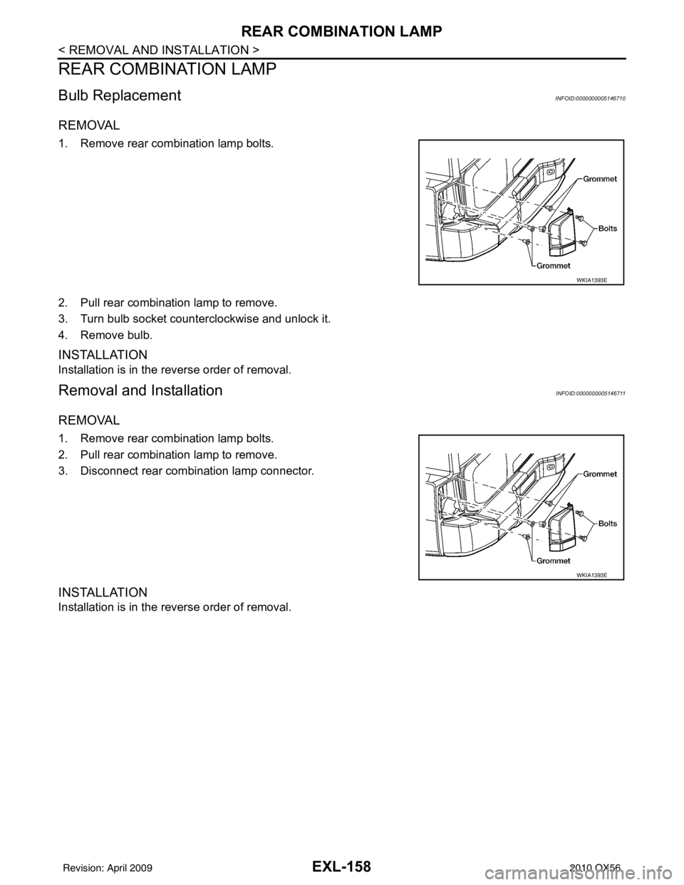
Bulb ReplacementINFOID:0000000005146710
REMOVAL
1. Remove rear combination lamp bolts.
2. Pull rear combination lamp to remove.
3. Turn bulb socket counterclockwise and unlock it.
4. Remove bulb.
INSTALLATION
Installation is in the reverse order of removal.
Removal and InstallationINFOID:0000000005146711
REMOVAL
1. Remove rear combination lamp bolts.
2. Pull rear combination lamp to remove.
3. Disconnect rear combination lamp connector.
INSTALLATION
Installation is in the reverse order of removal.
WKIA1393E
WKIA1393E
Revision: April 20092010 QX56
Page 2135 of 4210

BULB SPECIFICATIONSEXL-159
< SERVICE DATA AND SPECIFICATIONS (SDS)
C
DE
F
G H
I
J
K
M A
B
EXL
N
O P
SERVICE DATA AND SPECIFICATIONS (SDS)
BULB SPECIFICATIONS
HeadlampINFOID:0000000005146712
*: Always check with the Parts Department for the latest parts information.
Exterior LampINFOID:0000000005146713
*: Always check with the Parts Department for the latest parts information. Item
Wattage (W)*
Low 35
High 60/65
ItemWattage (W)*
Front combination lamp Parking lamp (inner)
7
Parking lamp (outer) 7
Side marker lamp (front) 7
Rear combination lamp Stop/Tail lamp
LED*
Side marker lamp (rear) *
Turn signal lamp 27
Back-up lamp *
Turn/fog lamp Fog
55
Turn 21
Puddle lamp 8
License plate lamp *
High-mounted stop lamp LED*
Revision: April 20092010 QX56
Page 2159 of 4210

EXT-24
< SERVICE INFORMATION >
LICENSE LAMP FINISHER
LICENSE LAMP FINISHER
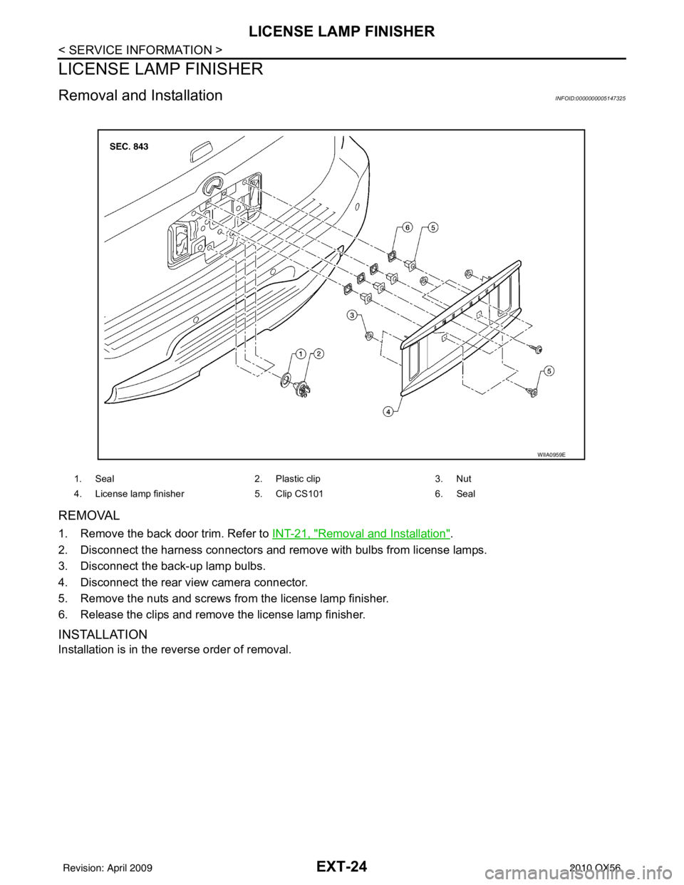
Removal and InstallationINFOID:0000000005147325
REMOVAL
1. Remove the back door trim. Refer to INT-21, "Removal and Installation".
2. Disconnect the harness connectors and remove with bulbs from license lamps.
3. Disconnect the back-up lamp bulbs.
4. Disconnect the rear view camera connector.
5. Remove the nuts and screws from the license lamp finisher.
6. Release the clips and remove the license lamp finisher.
INSTALLATION
Installation is in the reverse order of removal.
1. Seal 2. Plastic clip3. Nut
4. License lamp finisher 5. Clip CS101 6. Seal
WIIA0959E
Revision: April 20092010 QX56
Page 2267 of 4210

GI-44
< BASIC INSPECTION >
SERVICE INFORMATION FOR ELECTRICAL INCIDENT
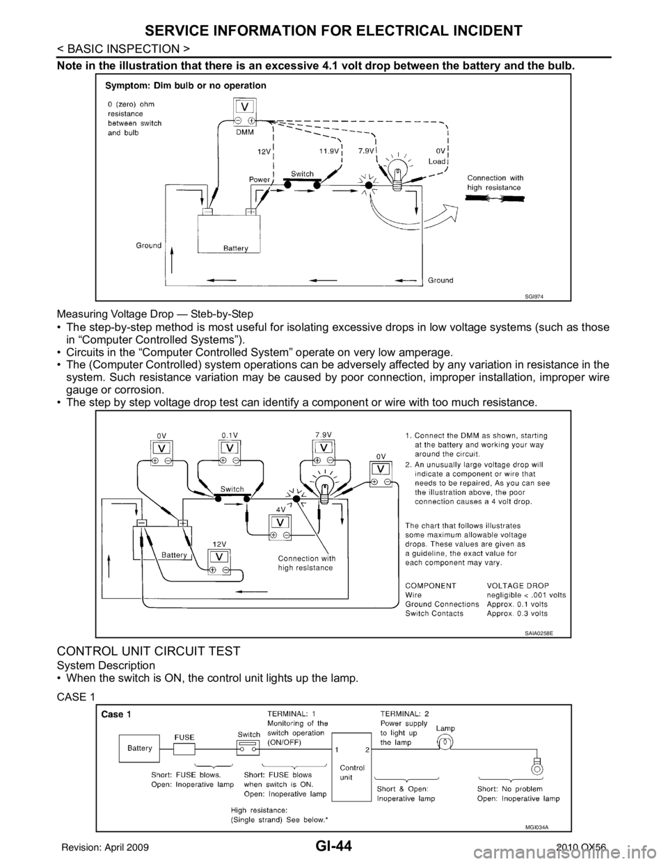
Note in the illustration that there is an excessive 4.1 volt drop between the battery and the bulb.
Measuring Voltage Drop — Steb-by-Step
• The step-by-step method is most useful for isolating excessive drops in low voltage systems (such as those
in “Computer Controlled Systems”).
• Circuits in the “Computer Controlled System” operate on very low amperage.
• The (Computer Controlled) system oper ations can be adversely affected by any variation in resistance in the
system. Such resistance variation may be caused by poor connection, improper installation, improper wire
gauge or corrosion.
• The step by step voltage drop test can identify a component or wire with too much resistance.
CONTROL UNIT CIRCUIT TEST
System Description
• When the switch is ON, the control unit lights up the lamp.
CASE 1
SGI974
SAIA0258E
MGI034A
Revision: April 20092010 QX56
Page 2471 of 4210

INL-2
DTC Index ..............................................................72
SYMPTOM DIAGNOSIS .............................74
INTERIOR LIGHTING SYSTEM SYMPTOMS ...74
Symptom Table ................................................... ...74
PRECAUTION .............................................75
PRECAUTIONS .............................................. ...75
Precaution for Supplemental Restraint System
(SRS) "AIR BAG" and "SEAT BELT PRE-TEN-
SIONER" .............................................................. ...
75
Precaution Necessary for Steering Wheel Rota-
tion After Battery Disconnect ..................................
75
General precautions for service operations ......... ...76
ON-VEHICLE REPAIR ...............................77
INTERIOR ROOM LAMP ................................ ...77
Removal and Installation .........................................77
ILLUMINATION .............................................. ...81
Removal and Installation .........................................81
SERVICE DATA AND SPECIFICATIONS
(SDS) .......... ................................. ...............
83
BULB SPECIFICATIONS ............................... ...83
Interior Lamp/Illumination ........................................83
Revision: April 20092010 QX56
Page 2488 of 4210

INTERIOR ROOM LAMP CONTROL CIRCUITINL-19
< COMPONENT DIAGNOSIS >
C
DE
F
G H
I
J
K
M A
B
INL
N
O P
INTERIOR ROOM LAMP CONTROL CIRCUIT
DescriptionINFOID:0000000005146730
Controls the following interior room lamps (ground side) by PWM signal
• Puddle lamps
• Front room/map lamp assembly
• Personal lamp 2nd row
• Personal lamp 3rd row
NOTE:
PWM signal control period is approximately 250 Hz (in the gradual brightening/dimming).
Component Function CheckINFOID:0000000005146731
CAUTION:
Before performing the diagnosis, check that the following is normal.
• Battery saver output/power supply
• Front room/map lamp bulbs
• Personal lamp bulbs
• Puddle lamp bulbs
1.CHECK INTERIOR ROOM LAMP CONTROL FUNCTION
CONSULT-III
1. Switch the front room/map lamp assembly switch to DOOR.
2. Turn ignition switch ON.
3. Select “INT LAMP” of BCM (INT LAMP) active test item.
4. While operating the test item, check that each interi or room lamp turns ON/OFF (gradual brightening/dim-
ming).
Is the inspection result normal?
YES >> Interior room lamp control circuit is normal.
NO >> Refer to INL-19, "
Diagnosis Procedure".
Diagnosis ProcedureINFOID:0000000005146732
Regarding Wiring Diagram information, refer to INL-28, "Wiring Diagram".
1.CHECK INTERIOR ROOM LAMP CONTROL OUTPUT
CONSULT-III
1. Switch the front room/map lamp assembly switch to DOOR.
2. Turn ignition switch ON.
3. Select “INT LAMP” of BCM (INT LAMP) active test item.
4. While operating the test item, check voltage between BCM con- nector M20 terminal 63 and ground.
Is the inspection result normal?
YES >> Interior room lamp control circuit is operating normally.
Fixed ON>>GO TO 3
Fixed OFF>>GO TO 2 ON : Interior room lamp gradual brightening
OFF : Interior room lamp gradual dimming
(+)
(-) INT LAMP Voltage
Connector Terminal
M20 63 Ground ON
0V
OFF Battery voltage
ALLIA0410GB
Revision: April 20092010 QX56
Page 2491 of 4210

INL-22
< COMPONENT DIAGNOSIS >
STEP LAMP CIRCUIT
STEP LAMP CIRCUIT
DescriptionINFOID:0000000005146733
Controls the front and rear step lamps and the foot lamps (ground side) to turn the lamps ON and OFF.
Component Function CheckINFOID:0000000005146734
CAUTION:
Before performing the diagnosis, check that the following is normal.
• Battery saver output/power supply
• Front step lamp bulbs
• Rear step lamp bulbs
• Foot lamp bulbs
1.CHECK STEP LAMP OPERATION
CONSULT-III
1. Turn ignition switch ON.
2. Select “STEP LAMP TEST” of BCM (INT LAMP) active test item.
3. While operating the test item, check that the front/rear step lamps and foot lamps turn ON/OFF.
Is the inspection result normal?
YES >> Step lamp circuit is normal.
NO >> Refer to INL-22, "
Diagnosis Procedure".
Diagnosis ProcedureINFOID:0000000005146735
Regarding Wiring Diagram information, refer to INL-28, "Wiring Diagram".
1.CHECK STEP LAMP OUTPUT
CONSULT-III
1. Turn ignition switch ON.
2. Select “STEP LAMP TEST” of BCM (INT LAMP) active test item.
3. While operating the test item, check voltage between BCM har- ness connector M20 terminal 62 and ground.
Is the inspection result normal?
YES >> Step lamp circuit is operating normally.
Fixed ON>>GO TO 3
Fixed OFF>>GO TO 2
2.CHECK STEP LAMP OPEN CIRCUIT ON : Step lamp ON
OFF : Step lamp OFF
Connector Terminal —
STEP LAMP
TEST Voltag e
M20 62 Ground ON
0V
OFF Battery voltage
ALLIA0414GB
Revision: April 20092010 QX56