light INFINITI QX56 2010 Factory Service Manual
[x] Cancel search | Manufacturer: INFINITI, Model Year: 2010, Model line: QX56, Model: INFINITI QX56 2010Pages: 4210, PDF Size: 81.91 MB
Page 3606 of 4210

SRC-60
< COMPONENT DIAGNOSIS >
B1113 – B1115 SATELLITE SENSOR RH
2.IGNITION SWITCH
After air bag warning lamp lights for 7 seconds, turn ignition switch OFF within 1 second.
>> GO TO 3
3.WAIT TIME
Wait more than 3 seconds.
>> GO TO 4
4.REPEAT STEPS
Repeat steps 1 to 3 twice.
>> GO TO 5
5.IGNITION SWITCH
Turn ignition switch ON.
>> GO TO 6
6.DIAGNOSTIC MODE
SRS system is now in diagnostic mode and AIR BAG warning lamp flashes. Refer to SRC-84, "
Trouble Diag-
nosis without CONSULT-III".
>> END
Diagnosis Procedure (C omponent Diagnosis)INFOID:0000000005147833
Recheck SRS after each replacement.
1.HARNESS CONNECTOR
Is there any visible damage to the connector?
YES or NO
YES >> Replace the harness.
NO >> GO TO 2
2.WIRING HARNESS
Is there any visible damage to the harness?
YES or NO
YES >> Replace the harness.
NO >> GO TO 3
3.RH SIDE AIR BAG SATELLITE SENSOR
Replace the RH side air bag satellite sensor. Refer to SR-15, "
Removal and Installation".
>> GO TO 4
4.AIR BAG DIAGNOSIS SENSOR UNIT
Replace the air bag diagnosis sensor unit. Refer to SR-17, "
Removal and Installation".
>> GO TO 5
5.RELATED HARNESS
Replace the related harness.
Revision: April 20092010 QX56
Page 3609 of 4210

B1XXX AIR BAG DIAGNOSIS SENSOR UNITSRC-63
< COMPONENT DIAGNOSIS >
C
DE
F
G
I
J
K L
M A
B
SRC
N
O P
2.IGNITION SWITCH
After air bag warning lamp lights for 7 seconds, turn ignition switch OFF within 1 second.
>> GO TO 3
3.WAIT TIME
Wait more than 3 seconds.
>> GO TO 4
4.REPEAT STEPS
Repeat steps 1 to 3 twice.
>> GO TO 5
5.IGNITION SWITCH
Turn ignition switch ON.
>> GO TO 6
6.DIAGNOSTIC MODE
SRS system is now in diagnostic mode and AIR BAG warning lamp flashes. Refer to SRC-84, "
Trouble Diag-
nosis without CONSULT-III".
>> END
Diagnosis Procedure (C omponent Diagnosis)INFOID:0000000005147836
Recheck SRS after each replacement.
1.HARNESS CONNECTOR
Is there any visible damage to the connector?
YES or NO
YES >> Replace the harness.
NO >> GO TO 2
2.WIRING HARNESS
Is there any visible damage to the harness?
YES or NO
YES >> Replace the harness.
NO >> GO TO 3
3.AIR BAG DIAGNOSIS SENSOR UNIT
Replace the air bag diagnosis sensor unit. Refer to SR-17, "
Removal and Installation".
>> GO TO 4
4.RELATED HARNESS
Replace the related harness.
>>END
Revision: April 20092010 QX56
Page 3611 of 4210

B1023 PASSENGER AIR BAG OFF INDICATORSRC-65
< COMPONENT DIAGNOSIS >
C
DE
F
G
I
J
K L
M A
B
SRC
N
O P
>> GO TO 2
2.IGNITION SWITCH
After air bag warning lamp lights for 7 seconds, turn ignition switch OFF within 1 second.
>> GO TO 3
3.WAIT TIME
Wait more than 3 seconds.
>> GO TO 4
4.REPEAT STEPS
Repeat steps 1 to 3 twice.
>> GO TO 5
5.IGNITION SWITCH
Turn ignition switch ON.
>> GO TO 6
6.DIAGNOSTIC MODE
SRS system is now in diagnostic mode and AIR BAG warning lamp flashes. Refer to SRC-84, "
Trouble Diag-
nosis without CONSULT-III".
>> END
Diagnosis Procedure (C omponent Diagnosis)INFOID:0000000005147839
Recheck SRS after each replacement.
1.HARNESS CONNECTOR
Is there any visible damage to the connector?
YES or NO
YES >> Replace the harness.
NO >> GO TO 2
2.WIRING HARNESS
Is there any visible damage to the harness?
YES or NO
YES >> Replace the harness.
NO >> GO TO 3
3.FRONT PASSENGER AIR BAG OFF INDICATOR
Replace the front passenger air bag off indicator. Refer to IP-15, "
Removal and Installation".
>> GO TO 4
4.AIR BAG DIAGNOSIS SENSOR UNIT
Replace the air bag diagnosis sensor unit. Refer to SR-17, "
Removal and Installation".
>> GO TO 5
5.RELATED HARNESS
Replace the related harness.
Revision: April 20092010 QX56
Page 3614 of 4210

SRC-68
< COMPONENT DIAGNOSIS >
B1017 – B1022 OCCUPANT CLASSIFICATION SYSTEM
2.CHECK SELF-DIAG RESULT
Check for the DTC on CONSULT-lll.
Is the DTC detected?
YES >> Refer to SRC-68, "Diagnosis Procedure (Component Diagnosis)".
NO >> Inspection End.
DTC CONFIRMATION PROCEDURE (Without CONSULT-lll)
NOTE:
SRS will not enter diagnosis mode if no malfunction is detected in user mode.
1.IGNITION SWITCH
Turn ignition switch ON.
>> GO TO 2
2.IGNITION SWITCH
After air bag warning lamp lights for 7 seconds, turn ignition switch OFF within 1 second.
>> GO TO 3
3.WAIT TIME
Wait more than 3 seconds.
>> GO TO 4
4.REPEAT STEPS
Repeat steps 1 to 3 twice.
>> GO TO 5
5.IGNITION SWITCH
Turn ignition switch ON.
>> GO TO 6
6.DIAGNOSTIC MODE
SRS system is now in diagnostic mode and AIR BAG warning lamp flashes. Refer to SRC-84, "
Trouble Diag-
nosis without CONSULT-III".
>> END
Diagnosis Procedure (C omponent Diagnosis)INFOID:0000000005147842
Recheck SRS after each replacement.
1.DTC
Does CONSULT-III indicate B1019 or B1022?
YES or NO
YES >> GO TO 2
NO >> GO TO 6
2.HARNESS CONNECTOR
Is there any visible damage to the connector?
YES or NO
YES >> Replace the harness.
NO >> GO TO 3
Revision: April 20092010 QX56
Page 3637 of 4210

PASSENGER SEAT BELT WARNING SYSTEMSRC-91
< SYMPTOM DIAGNOSIS >
C
DE
F
G
I
J
K L
M A
B
SRC
N
O P
PASSENGER SEAT BELT WARNING SYSTEM
Seat Belt Warning Syst em Does Not FunctionINFOID:0000000005147851
1.SEAT BELT WARNING LIGHT
Turn ignition switch ON.
Does the seat belt warning lamp come ON?
YES >> GO TO 2
NO >> • Check 10A fuse [No. 14, loca ted in the fuse block (J/B)].
• Check seat belt buckle switch LH.
• Check harness between combination meter and seat belt buckle switch LH.
• Check combination meter. Refer to MWI-23, "
CONSULT-III Function (METER/M&A)".
2.SEAT BELT BUCKLE LH
Fasten the seat belt buckle LH.
Does the seat belt warning lamp go OFF?
YES >> GO TO 3
NO >> • Check seat belt buckle switch LH. • Check harness between combination meter and seat belt buckle switch LH.
3.OCCUPANT CLASSIFICATION SYSTEM
Have a helper sit in the passenger seat.
Does the seat belt warning lamp go ON?
YES >> GO TO 4
NO >> • Check occupant classification system. Refer to SRC-10, "
Occupant Classification System
(OCS)".
• Check harness between occupant classification control unit and air bag diagnosis sensor unit.
4.SEAT BELT BUCKLE RH
Fasten the seat belt buckle RH.
Does the seat belt warning lamp go OFF?
YES >> System OK.
NO >> • Check seat belt buckle switch RH. • Check harness between seat belt buckle switch RH and air bag diagnosis sensor unit.
• Replace air bag diagnosis sensor unit. Refer to SR-17, "
Removal and Installation".
Revision: April 20092010 QX56
Page 3645 of 4210

HEATED STEERING WHEELST-7
< FUNCTION DIAGNOSIS >
C
DE
F
H I
J
K L
M A
B
ST
N
O P
FUNCTION DIAGNOSIS
HEATED STEERING WHEEL
System DiagramINFOID:0000000005147859
System DescriptionINFOID:0000000005147860
The heated steering wheel switch controls the heated steeri ng relay. When the switch is turned on, the relay is
energized and the heated steering system will operate. T he heated steering system will turn off when the
steering wheel temperature reaches approximately 86 ° F (30 ° C). Heated steering system operation can also
be canceled by pressing the heated steering wheel switch again.
NOTE:
If the surface temperature of the steering wheel is below 68 ° F (20 ° C), the system will heat the steering wheel
to approximately 86 ° F (30 ° C), and cycle off and on to maintain a temperature above 68 ° F (20 ° C). The indi-
cator light will remain on as long as the system is on. Push the switch again to turn the heated steering wheel
system off manually. The indicator light will go off.
Component Parts LocationINFOID:0000000005147861
AWGIA0022GB
1. Heated steering relay M71 2. Combination switch (spiral cable) M52 3. Heated steering wheel M114
4. Heated steering wheel switch M260
ALGIA0030ZZ
Revision: April 20092010 QX56
Page 3653 of 4210

STEERING WHEELST-15
< ON-VEHICLE REPAIR >
C
DE
F
H I
J
K L
M A
B
ST
N
O P
ON-VEHICLE REPAIR
STEERING WHEEL
On-Vehicle Inspection and ServiceINFOID:0000000005147868
CHECKING CONDITION OF INSTALLATION
• Check installation condition of steering gear assembly, front suspension, axle and steering column.
• Check if movement exists when steering wheel is mo ved up and down, to the left and right and to the axial
direction.
• Check if the nuts for steering gear assembly are loose. Refer to ST-23, "
Removal and Installation".
CHECKING STEERING WHEEL PLAY
1. Turn tires straight ahead, start engine, then turn steer ing wheel to the left and right lightly, and measure
steering wheel movement on the outer circumference when steering wheel is turned up to the point where
tires start moving.
CHECKING NEUTRAL POSITION ON STEERING WHEEL
• Check neutral position on steering wheel after confirming that front wheel alignment is correct. Refer to FSU-
6, "Front Wheel Alignment".
1. Turn tires straight ahead, check if steering wheel is in the neutral position.
2. If it is not in the neutral position, remo ve steering wheel and reinstall it correctly.
3. If the neutral position cannot be attained by repositi oning the steering wheel two teeth or less on steering
stem, loosen tie-rod lock nuts of steering outer socket s, then adjust tie-rods by the same amount in the
opposite direction.
CHECKING STEERING WHEEL TURNING FORCE
1. Park vehicle on a level, dry surface and set parking brake.
2. Start engine.
3. Bring power steering fluid up to operating temperature of 60 °– 80° C (140° – 176°F).
4. Tires need to be inflated to specified pressure. Refer to WT-52, "
Tire".
5. Check steering wheel turning force using Tool when steering wheel has been turned 360 ° from the neutral position.
End play of the axial direction for steering wheel : Refer to
ST-35, "
Steering Wheel".
LGIA0024E
Steering wheel play on the outer circumference : Refer to ST-35, "Steering Wheel".
Tool number — (J-44372)
Steering wheel
turning force : Refer to
ST-35, "
Steering
Wheel".
WGIA0035E
Revision: April 20092010 QX56
Page 3726 of 4210

ON BOARD DIAGNOSTIC (OBD) SYSTEMTM-31
< FUNCTION DIAGNOSIS >
CEF
G H
I
J
K L
M A
B
TM
N
O P
longer stored. Remember, only one set of freeze frame data can be stored in the ECM. The ECM has the fol-
lowing priorities to update the data.
Both 1st trip freeze frame data and freeze frame data (along with the DTC) are cleared when the ECM mem-
ory is erased.
HOW TO ERASE DTC
The diagnostic trouble code can be erased by CONSULT- III, GST or ECM DIAGNOSTIC TEST MODE as
described following.
• If the battery cable is disconnected, the diagnostic trouble code will be lost within 24 hours.
• When you erase the DTC, using CONSULT-III or GS T is easier and quicker than switching the mode
selector on the ECM.
The following emission-related diagnostic information is cleared from the ECM memory when erasing DTC
related to OBD-II. For details, refer to EC-42, "
Emission-related Diagnostic Information".
• Diagnostic trouble codes (DTC)
• 1st trip diagnostic trouble codes (1st trip DTC)
• Freeze frame data
• 1st trip freeze frame data
• System readiness test (SRT) codes
• Test values
HOW TO ERASE DTC (WITH CONSULT-III)
1. The emission related diagnostic information in the TCM and ECM can be er\
ased by selectioning "ALL
ERASE" in the "Description" of "F INAL CHECK" mode with CONSULT-III.
HOW TO ERASE DTC (WITH GST)
1. If the ignition switch stays “ON” after repair work, be sure to turn ignition switch “OFF” once. Wait at least
10 seconds and then turn it “ON” (engine stopped) again.
2. Select Mode 4 with the Generic Scan Tool (GST). For details refer to EC-72, "
Generic Scan Tool (GST)
Function".
HOW TO ERASE DTC (NO TOOLS)
1. Disconnect battery for 24 hours.
2. Reconnect battery.
Malfunction Indicator Lamp (MIL)INFOID:0000000005148525
DESCRIPTION
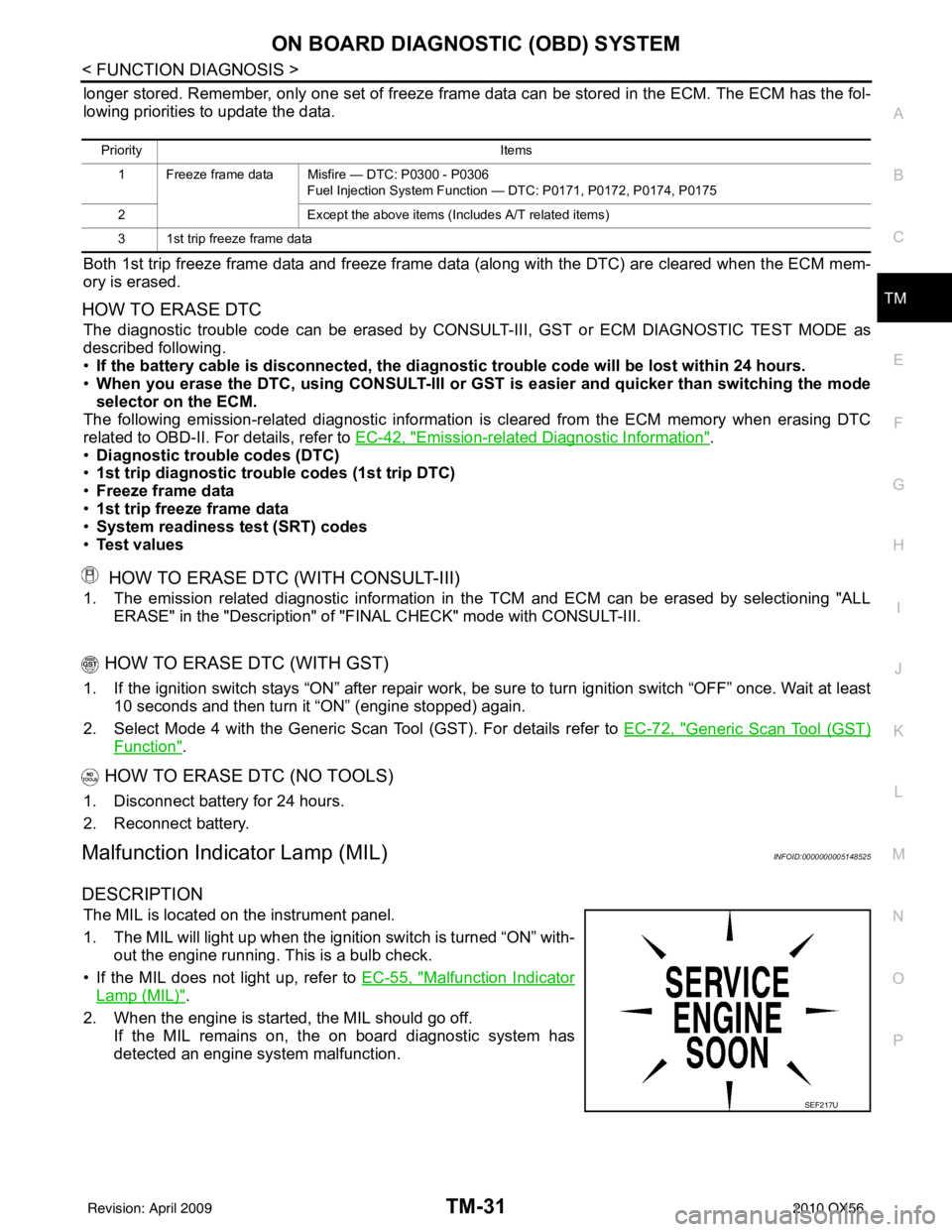
The MIL is located on the instrument panel.
1. The MIL will light up when the ignition switch is turned “ON” with-
out the engine running. This is a bulb check.
• If the MIL does not light up, refer to EC-55, "
Malfunction Indicator
Lamp (MIL)".
2. When the engine is start ed, the MIL should go off.
If the MIL remains on, the on board diagnostic system has
detected an engine system malfunction.
Priority Items
1 Freeze frame data Misfire — DTC: P0300 - P0306 Fuel Injection System Function — DTC: P0171, P0172, P0174, P0175
2 Except the above items (Includes A/T related items)
3 1st trip freeze frame data
SEF217U
Revision: April 20092010 QX56
Page 3732 of 4210

DIAGNOSIS SYSTEM (TCM)TM-37
< FUNCTION DIAGNOSIS >
CEF
G H
I
J
K L
M A
B
TM
N
O P
DTC & SRT CONFIRMATION
DTC Work Support Mode
Diagnosis Procedure without CONSULT-IIIINFOID:0000000005148527
OBD-II SELF-DIAGNOSTIC PROCEDURE (WITH GST)
Refer to EC-72, "Generic Scan Tool (GST) Function".
OBD-II SELF-DIAGNOSTIC PROCEDURE (NO TOOLS)
Refer to EC-55, "Malfunction Indicator Lamp (MIL)".
TCM SELF-DIAGNOSTIC PROCEDURE (NO TOOLS)
Description
When the ignition switch is switched “ON”, the A/T CHECK indicator lamp lights up for 2 seconds. As a method
for locating the suspect circuit, when the self-diagnosti cs start signal is input, the memory for the malfunction
location is output and the A/T CHECK indicator lamp flashes to display the corresponding DTC.
Diagnostic Procedure
1.CHECK A/T CHECK INDICATOR LAMP
1. Start the engine with selector lever in “P” pos ition. Warm engine to normal operating temperature.
2. Turn ignition switch ON and OFF at least twice, then leave it in the OFF position.
3. Wait 10 seconds.
4. Turn ignition switch ON. (Do not start engine.)
Frequency (Hz) —— X
The value measured by the pulse probe is dis-
played.
DUTY-HI (high) (%)
—— X
DUTY-LOW (low) (%) —— X
PLS WIDTH-HI (ms) —— X
PLS WIDTH-LOW (ms) —— X
Monitored item (Unit)
Monitor Item Selection
Remarks
ECU IN-
PUT SIG- NALS MAIN SIG-
NALS SELEC-
TION
FROM
MENU
DTC work support item DescriptionCheck item
1ST GR FNCTN P0731 Following items for “1GR function ratio” be confirmed.
• Self-diagnosis status (whether the diagnosis is being performed
or not)
• Self-diagnosis result (OK or NG)
• Input clutch solenoid valve
• Front brake solenoid valve
• Direct clutch solenoid valve
• High and low reverse clutch solenoid valve
• Each clutch
• Hydraulic co ntrol circuit
valve
2ND GR FNCTN P0732
Following items for “2GR function ratio” be confirmed.
• Self-diagnosis status (whether the diagnosis is being performed
or not)
• Self-diagnosis result (OK or NG)
3RD GR FNCTN P0733 Following items for “3GR function ratio” be confirmed.
• Self-diagnosis status (whether the diagnosis is being performed
or not)
• Self-diagnosis result (OK or NG)
4TH GR FNCTN P0734 Following items for “4GR function ratio” be confirmed.
• Self-diagnosis status (whether the diagnosis is being performed
or not)
• Self-diagnosis result (OK or NG)
5TH GR FNCTN P0735 Following items for “5GR function ratio” be confirmed.
• Self-diagnosis status (whether the diagnosis is being performed
or not)
• Self-diagnosis result (OK or NG)
Revision: April 20092010 QX56
Page 3733 of 4210

TM-38
< FUNCTION DIAGNOSIS >
DIAGNOSIS SYSTEM (TCM)
Does A/T CHECK indicator lamp come on for about 2 seconds?
YES >> GO TO 2.
NO >> GO TO TM-121, "
Symptom Table".
2.JUDGMENT PROCEDURE STEP 1
1. Turn ignition switch OFF.
2. Keep pressing shift lock release button.
3. Move selector lever from “P” to “D” position.
4. Release accelerator pedal. (Set the closed throttle position signal “ON”.)
5. Depress brake pedal. (Stop lamp switch signal “ON”.)
6. Turn ignition switch ON. (Do not start engine.)
7. Wait 3 seconds.
8. Move the selector lever from “D” to “3” position.
9. Release brake pedal. (Stop lamp switch signal “OFF”.)
10. Move the selector lever from “3” to “2” position.
11. Depress brake pedal. (Stop lamp switch signal “ON”.)
12. Depress accelerator pedal fully and release it.
>> GO TO 3.
3.CHECK SELF-DIAGNOSIS CODE
Check A/T CHECK indicator lamp.
Refer to "Judgment Self-diagnosis Code".
If the system does not go into self-diagnostics. Refer to TM-45, "
Diagnosis Procedure", TM-96, "Diagnosis
Procedure", TM-97, "Diagnosis Procedure".
>> DIAGNOSIS END
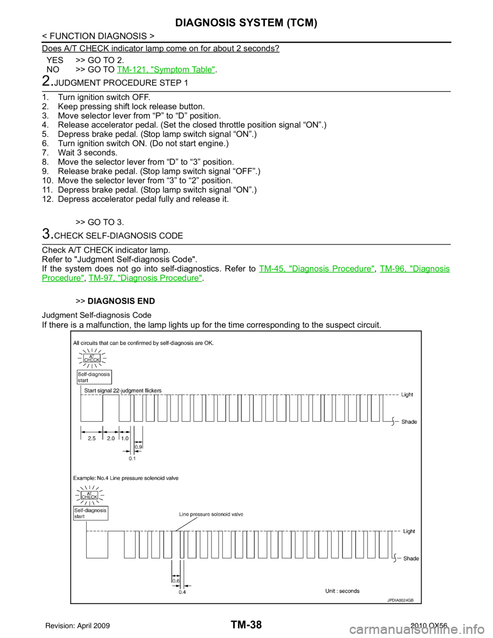
Judgment Self-diagnosis Code
If there is a malfunction, the lamp lights up for the time corresponding to the suspect circuit.
JPDIA0024GB
Revision: April 20092010 QX56