upper INFINITI QX56 2010 Factory Owner's Guide
[x] Cancel search | Manufacturer: INFINITI, Model Year: 2010, Model line: QX56, Model: INFINITI QX56 2010Pages: 4210, PDF Size: 81.91 MB
Page 1889 of 4210
EM-38
< ON-VEHICLE REPAIR >
ROCKER COVER
ROCKER COVER
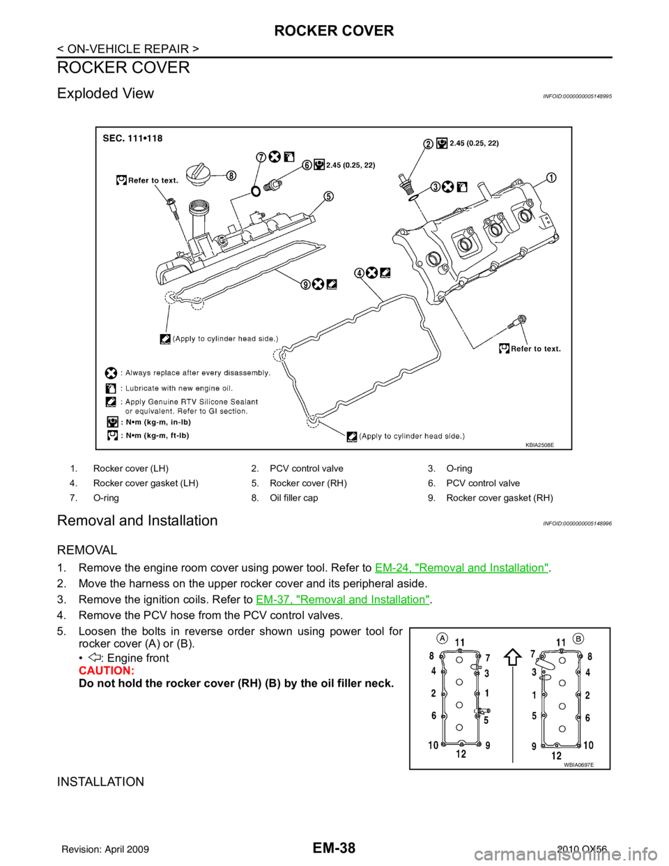
Exploded ViewINFOID:0000000005148995
Removal and InstallationINFOID:0000000005148996
REMOVAL
1. Remove the engine room cover using power tool. Refer to EM-24, "Removal and Installation".
2. Move the harness on the upper rocker cover and its peripheral aside.
3. Remove the ignition coils. Refer to EM-37, "
Removal and Installation".
4. Remove the PCV hose from the PCV control valves.
5. Loosen the bolts in reverse order shown using power tool for rocker cover (A) or (B).
• : Engine front
CAUTION:
Do not hold the rocker cover ( RH) (B) by the oil filler neck.
INSTALLATION
1. Rocker cover (LH) 2. PCV control valve3. O-ring
4. Rocker cover gasket (LH) 5. Rocker cover (RH)6. PCV control valve
7. O-ring 8. Oil filler cap9. Rocker cover gasket (RH)
KBIA2508E
WBIA0697E
Revision: April 20092010 QX56
Page 1892 of 4210
FUEL INJECTOR AND FUEL TUBEEM-41
< ON-VEHICLE REPAIR >
C
DE
F
G H
I
J
K L
M A
EM
NP
O
9. Remove fuel injector from fuel tube.
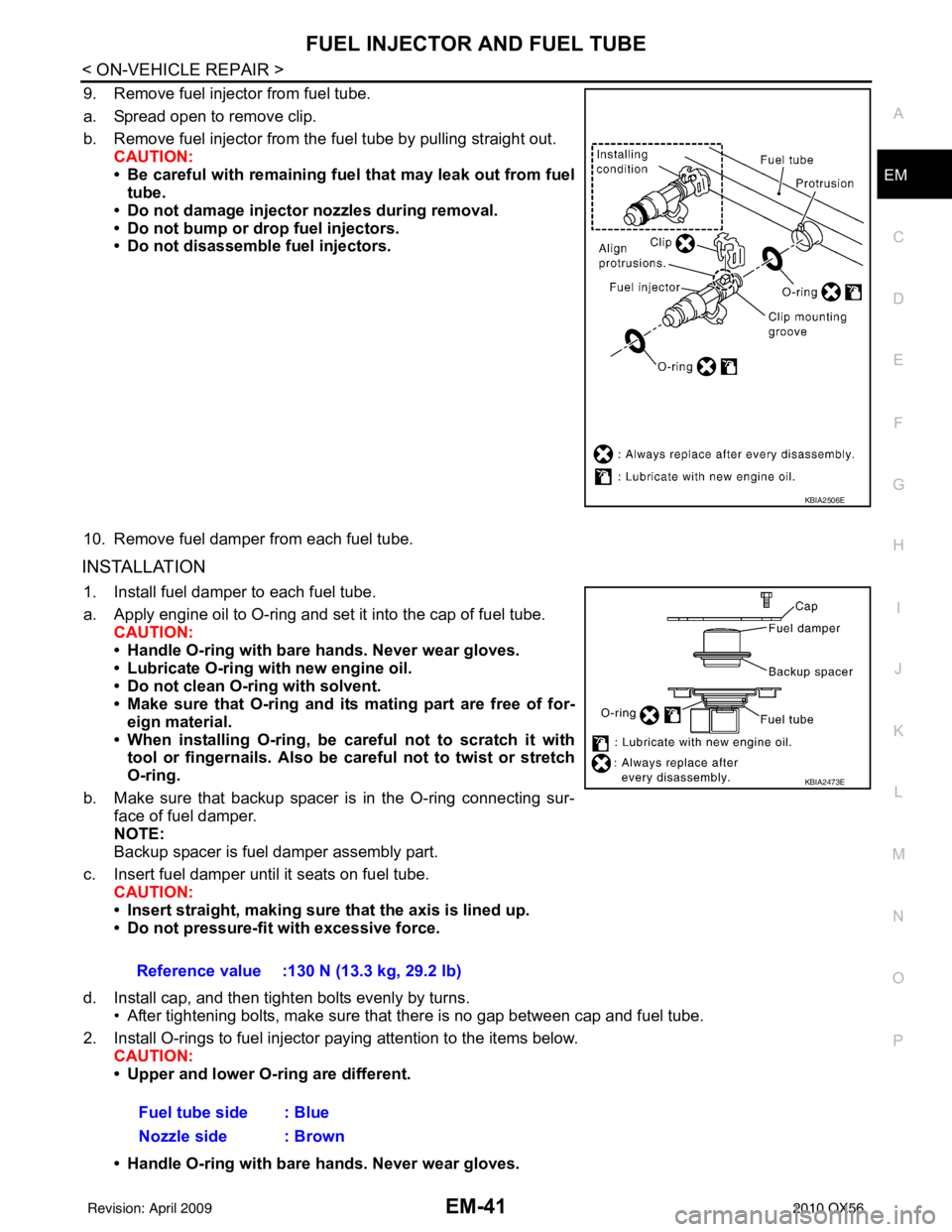
a. Spread open to remove clip.
b. Remove fuel injector from the
fuel tube by pulling straight out.
CAUTION:
• Be careful with remaining fuel that may leak out from fuel
tube.
• Do not damage injector nozzles during removal.
• Do not bump or drop fuel injectors.
• Do not disassemble fuel injectors.
10. Remove fuel damper from each fuel tube.
INSTALLATION
1. Install fuel damper to each fuel tube.
a. Apply engine oil to O-ring and set it into the cap of fuel tube. CAUTION:
• Handle O-ring with bare hands. Never wear gloves.
• Lubricate O-ring with new engine oil.
• Do not clean O-ring with solvent.
• Make sure that O-ring and its mating part are free of for- eign material.
• When installing O-ring, be car eful not to scratch it with
tool or fingernails. Also be careful not to twist or stretch
O-ring.
b. Make sure that backup spacer is in the O-ring connecting sur- face of fuel damper.
NOTE:
Backup spacer is fuel damper assembly part.
c. Insert fuel damper until it seats on fuel tube. CAUTION:
• Insert straight, making sure that the axis is lined up.
• Do not pressure-fit with excessive force.
d. Install cap, and then tighten bolts evenly by turns. • After tightening bolts, make sure that there is no gap between cap and fuel tube.
2. Install O-rings to fuel injector paying attention to the items below. CAUTION:
• Upper and lower O-ring are different.
• Handle O-ring with bare hands. Never wear gloves.
KBIA2506E
Reference value :130 N (13.3 kg, 29.2 lb)
Fuel tube side : Blue
Nozzle side : Brown
KBIA2473E
Revision: April 20092010 QX56
Page 1896 of 4210
TIMING CHAINEM-45
< ON-VEHICLE REPAIR >
C
DE
F
G H
I
J
K L
M A
EM
NP
O
Removal and InstallationINFOID:0000000005149000
NOTE:
• To remove timing chain and associated parts, start with those on the LH bank. The procedure for removing
parts on the RH bank is omitted because it is t he same as that for removal on the LH bank.
• To install timing chain and associated parts, start with those on the RH bank. The procedure for installing parts on the LH bank is omitted because it is t he same as that for installation on the RH bank.
REMOVAL
1. Remove the engine assembly from the vehicle. Refer to EM-78, "Removal and Installation".
2. Remove the following components and related parts: • Drive belt auto tensioner and idler pulley. Refer to EM-13, "
Removal and Installation".
• Thermostat housing and water hose. Refer to CO-22, "
Removal and Installation".
• Power steering oil pump bracket. Refer to ST-26, "
Removal and Installation".
• Oil pan (lower), (upper) and oil strainer. Refer to EM-33, "
Removal and Installation".
• Rocker cover. Refer to EM-38, "
Removal and Installation".
• Generator and generator bracket. Refer to CHG-21, "
Removal and Installation".
• Water pump. Refer to CO-20, "
Exploded View".
3. Disconnect and remove the camshaft position sensor.
4. Disconnect and remove the intake valve ti ming control position sensor (RH and LH).
5. Disconnect and remove the intake valve timing control solenoid valve (RH and LH).
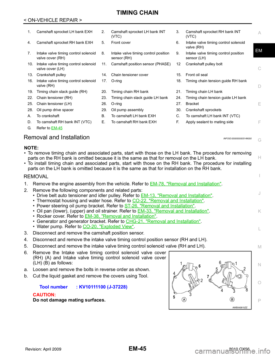
6. Remove the Intake valve timing control solenoid valve cover (RH) (A) and Intake valve timing control solenoid valve cover
(LH) (B) as follows:
a. Loosen and remove the bolts in reverse order as shown.
b. Cut the liquid gasket and remove the covers using Tool.
CAUTION:
Do not damage mating surfaces.
1. Camshaft sprocket LH bank EXH 2. Camshaft sprocket LH bank INT (VTC)3. Camshaft sprocket RH bank INT
(VTC)
4. Camshaft sprocket RH bank EXH 5. Front cover 6. Intake valve timing control solenoid
valve (RH)
7. Intake valve timing control solenoid valve cover (RH) 8. Intake valve timing control position
sensor (RH) 9. Intake valve timing control position
sensor (LH)
10. Intake valve timing control solenoid valve cover (LH) 11. Camshaft position
sensor (PHASE) 12 Cran kshaft pulley bolt
13. Crankshaft pulley 14. Chain tensioner cover 15. Front oil seal
16. Intake valve timing control solenoid valve (RH) 17. O-ring
18. Timing chain tension guide RH bank
19. Timing chain slack guide (RH) 20. Timing chain RH bank 21. Timing chain LH bank
22. Chain tensioner (RH) 23. Timing chain slack guide LH bank 24. Timing chain tension guide LH bank
25. Chain tensioner (LH) 26. O-ring 27. Bracket
28. Oil pump drive spacer 29. Oil pump assembly 30. Crankshaft sprockets
A. To crankshaft B. To camshaft LH bank EXH C. To camshaft LH bank INT (VTC)
D. To camshaft RH bank INT (VTC) E. To camshaft RH bank EXH F. Apply sealant to mating side
G. Refer to EM-45
Tool number : KV10111100 (J-37228)
AWBIA0815ZZ
Revision: April 20092010 QX56
Page 1911 of 4210
EM-60
< ON-VEHICLE REPAIR >
CAMSHAFT
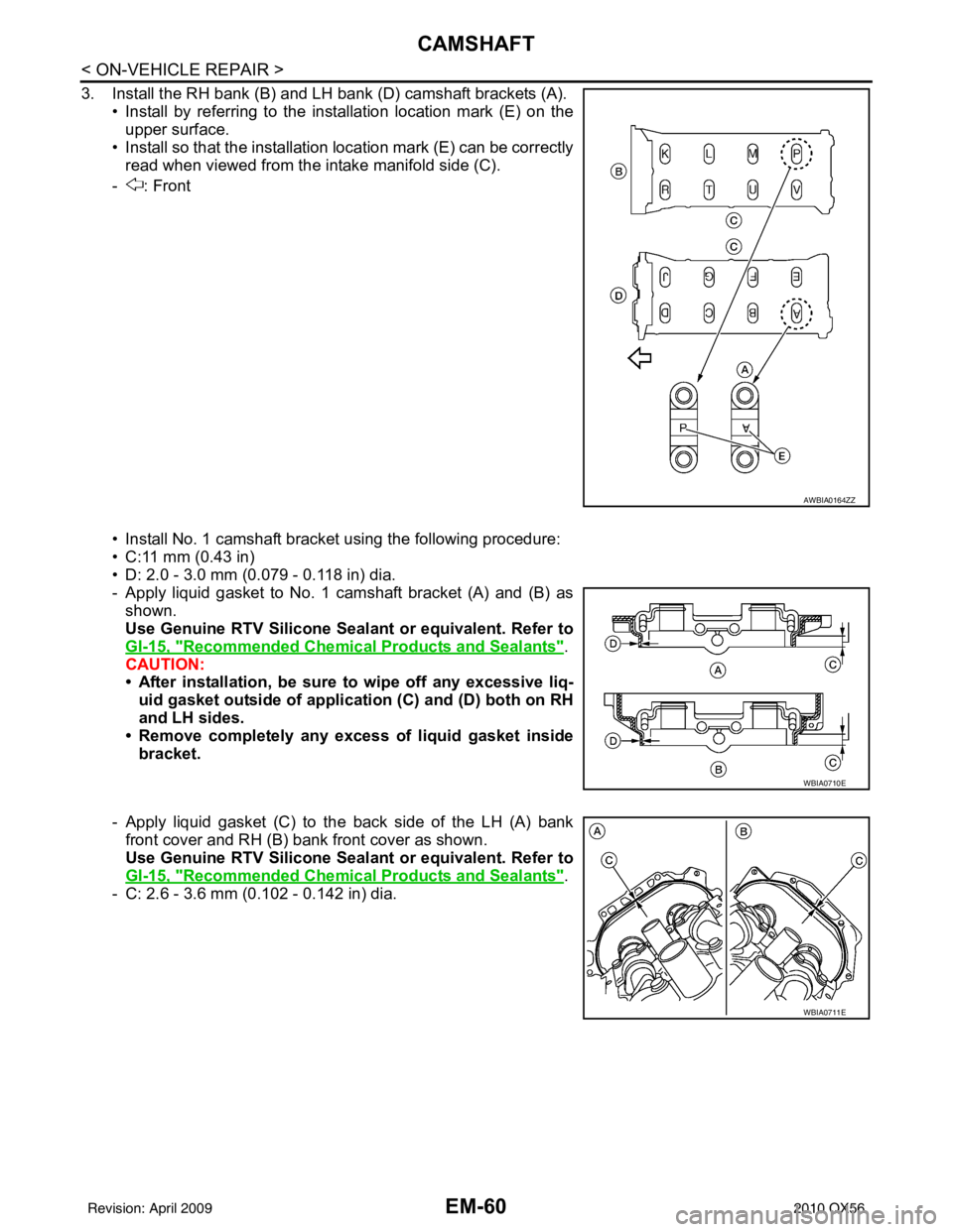
3. Install the RH bank (B) and LH bank (D) camshaft brackets (A).• Install by referring to the installation location mark (E) on theupper surface.
• Install so that the installation location mark (E) can be correctly read when viewed from the intake manifold side (C).
- : Front
• Install No. 1 camshaft bracket using the following procedure:
• C:11 mm (0.43 in)
• D: 2.0 - 3.0 mm (0.079 - 0.118 in) dia.
- Apply liquid gasket to No. 1 camshaft bracket (A) and (B) as shown.
Use Genuine RTV Silicone Seal ant or equivalent. Refer to
GI-15, "
Recommended Chemical Products and Sealants".
CAUTION:
• After installation, be sure to wipe off any excessive liq- uid gasket outside of applicat ion (C) and (D) both on RH
and LH sides.
• Remove completely any excess of liquid gasket inside
bracket.
- Apply liquid gasket (C) to the back side of the LH (A) bank front cover and RH (B) bank front cover as shown.
Use Genuine RTV Silicone Seal ant or equivalent. Refer to
GI-15, "
Recommended Chemical Products and Sealants".
- C: 2.6 - 3.6 mm (0.102 - 0.142 in) dia.
AWBIA0164ZZ
WBIA0710E
WBIA0711E
Revision: April 20092010 QX56
Page 1923 of 4210
EM-72
< ON-VEHICLE REPAIR >
CYLINDER HEAD
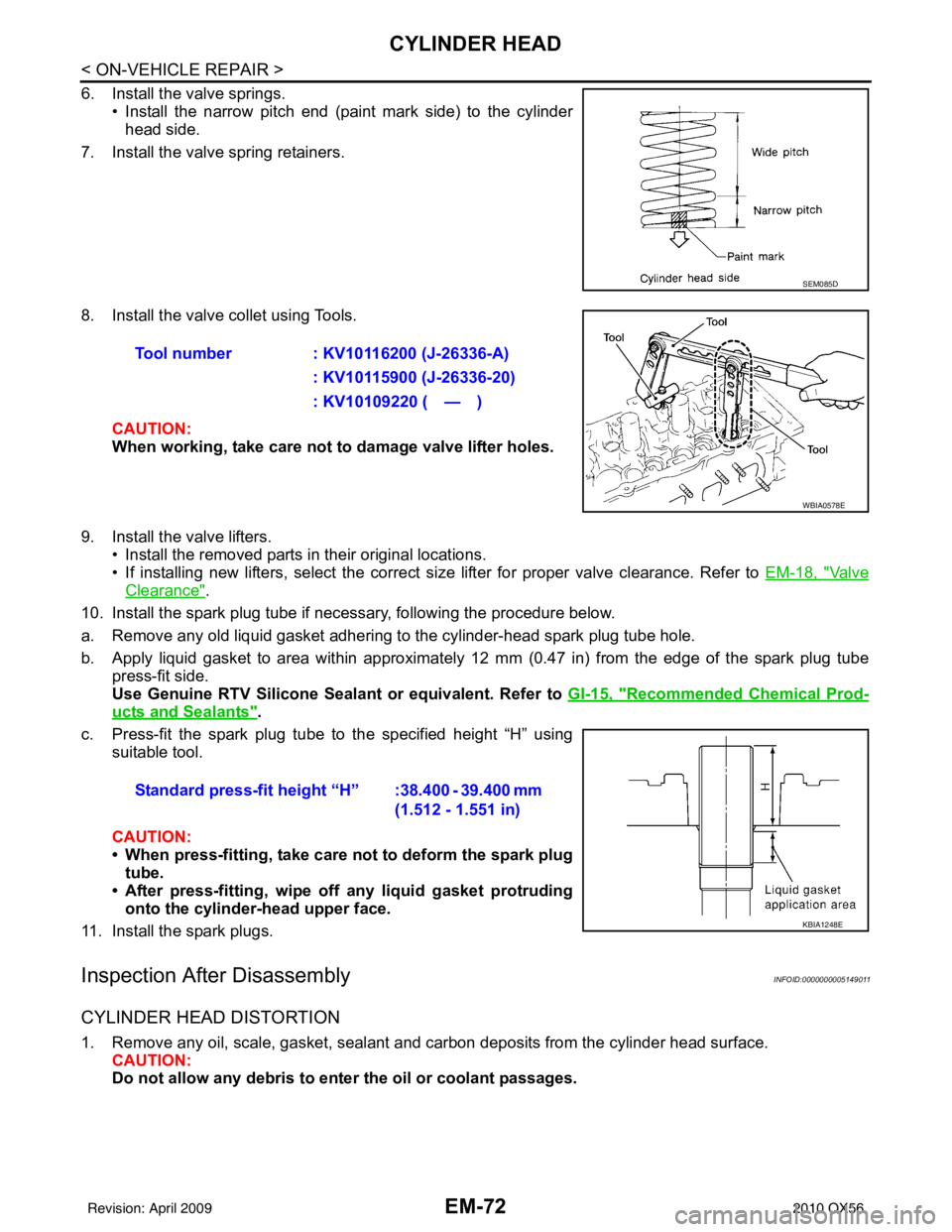
6. Install the valve springs.• Install the narrow pitch end (paint mark side) to the cylinderhead side.
7. Install the valve spring retainers.
8. Install the valve collet using Tools.
CAUTION:
When working, take care not to damage valve lifter holes.
9. Install the valve lifters. • Install the removed parts in their original locations.
• If installing new lifters, select the correct size lifter for proper valve clearance. Refer to EM-18, "
Va l v e
Clearance".
10. Install the spark plug tube if necessary, following the procedure below.
a. Remove any old liquid gasket adhering to the cylinder-head spark plug tube hole.
b. Apply liquid gasket to area within approximately 12 mm (0.47 in) from the edge of the spark plug tube
press-fit side.
Use Genuine RTV Silicone Seal ant or equivalent. Refer to GI-15, "
Recommended Chemical Prod-
ucts and Sealants".
c. Press-fit the spark plug tube to the specified height “H” using suitable tool.
CAUTION:
• When press-fitting, take care not to deform the spark plugtube.
• After press-fitting, wipe off any liquid gasket protruding
onto the cylinder-head upper face.
11. Install the spark plugs.
Inspection After DisassemblyINFOID:0000000005149011
CYLINDER HEAD DISTORTION
1. Remove any oil, scale, gasket, sealant and carbon deposits from the cylinder head surface. CAUTION:
Do not allow any debris to en ter the oil or coolant passages.
SEM085D
Tool number : KV10116200 (J-26336-A)
: KV10115900 (J-26336-20)
: KV10109220 ( — )
WBIA0578E
Standard press-fit height “H” :38.400 - 39.400 mm (1.512 - 1.551 in)
KBIA1248E
Revision: April 20092010 QX56
Page 1930 of 4210
ENGINE ASSEMBLYEM-79
< REMOVAL AND INSTALLATION >
C
DE
F
G H
I
J
K L
M A
EM
NP
O
1. Release the fuel pressure. Refer to
EC-489, "Fuel Pressure Check".
2. Drain the engine coolant. Refer to CO-11, "
Changing Engine Coolant".
3. Drain the engine oil. Refer to LU-9, "
Changing Engine Oil".
4. Partially drain the A/T fluid. Refer to TM-150, "
Changing the A/T Fluid (ATF)".
5. Disconnect the battery negative and positive terminal. Refer to PG-74, "
Removal and Installation".
6. Remove the engine hood. Refer to DLK-234, "
Removal and Installation of Hood Assembly".
7. Remove the cowl extension. Refer to EXT-18, "
Removal and Installation".
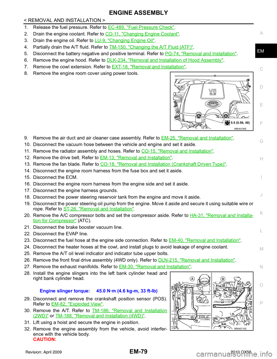
8. Remove the engine room cover using power tools.
9. Remove the air duct and air cleaner case assembly. Refer to EM-25, "
Removal and Installation".
10. Disconnect the vacuum hose between the vehicle and engine and set it aside.
11. Remove the radiator assembly and hoses. Refer to CO-15, "
Removal and Installation".
12. Remove the drive belt. Refer to EM-13, "
Removal and Installation".
13. Remove the fan blade. Refer to CO-18, "
Removal and Installation (Crankshaft Driven Type)".
14. Disconnect the engine room harness from the fuse box and set it aside.
15. Disconnect the ECM.
16. Disconnect the engine room harness from the engine side and set it aside.
17. Disconnect the engine harness grounds.
18. Disconnect the power steering reservoir t ank from the engine and move it aside.
19. Disconnect the power steering oil pump from the engine. Move it aside and secure it using suitable wire or rope. Refer to ST-26, "
Removal and Installation"
20. Remove the A/C compressor bolts and set the compressor aside. Refer to HA-31, "Removal and Installa-
tion for Compressor" (ATC).
21. Disconnect the brake booster vacuum line.
22. Disconnect the EVAP line.
23. Disconnect the fuel hose at the engine side connection. Refer to EM-40, "
Removal and Installation".
24. Disconnect the heater hoses at the cowl, and in stall plugs to avoid leakage of engine coolant.
25. Remove the A/T oil level indicator and indicator tube upper bolts.
26. Remove the front final drive assembly (4WD only). Refer to DLN-215, "
Removal and Installation".
27. Remove the exhaust manifolds. Refer to EM-30, "
Removal and Installation".
28. Install the engine slingers into the left bank cylinder head and right bank cylinder head.
29. Disconnect and remove the crankshaft position sensor (POS). Refer to EM-82, "
Exploded View".
30. Remove the A/T. Refer to TM-186, "
Removal and Installation
(2WD)" or TM-188, "Removal and Installation (4WD)".
31. Lift using a hoist and secure the engine in position.
32. Remove the engine assembly from the vehicle, avoid interfer- ence with the vehicle body.
CAUTION:
WBIA0795E
Engine slinger torque: 45.0 N·m (4.6 kg-m, 33 ft-lb)
WBIA0715E
Revision: April 20092010 QX56
Page 1933 of 4210
EM-82
< DISASSEMBLY AND ASSEMBLY >
ENGINE UNIT
DISASSEMBLY AND ASSEMBLY
ENGINE UNIT
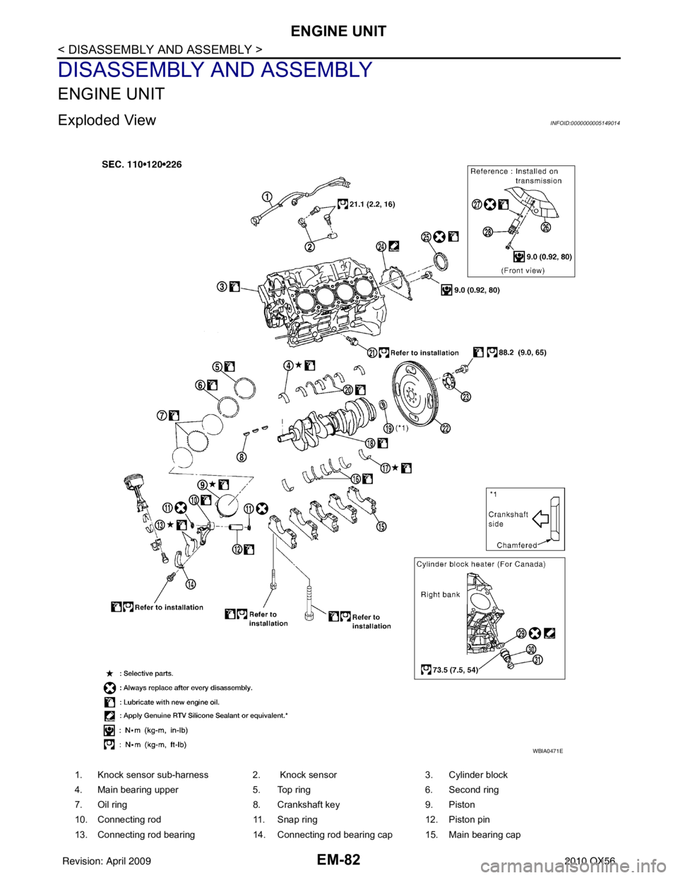
Exploded ViewINFOID:0000000005149014
1. Knock sensor sub-harness 2. Knock sensor3. Cylinder block
4. Main bearing upper 5. Top ring6. Second ring
7. Oil ring 8. Crankshaft key9. Piston
10. Connecting rod 11. Snap ring12. Piston pin
13. Connecting rod bearing 14. Connecting rod bearing cap 15. Main bearing cap
WBIA0471E
Revision: April 20092010 QX56
Page 1934 of 4210
ENGINE UNITEM-83
< DISASSEMBLY AND ASSEMBLY >
C
DE
F
G H
I
J
K L
M A
EM
NP
O
Disassembly and AssemblyINFOID:0000000005149015
DISASSEMBLY
NOTE:
Explained here is how to disassemble with engine stand supporting transmission surface. When using differ-
ent type of engine stand, some steps may be different.
1. Remove engine assembly and mount to engine stand. Refer to
EM-78, "
Removal and Installation".
CAUTION:
Before removing the hanging chains, make sure engi ne stand is stable and there is no risk of over-
turning.
2. Drain engine oil. Refer to LU-9, "
Changing Engine Oil".
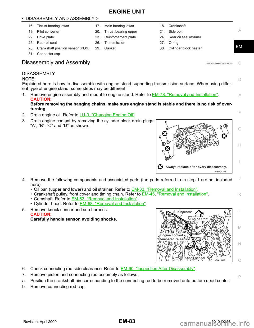
3. Drain engine coolant by removing the cylinder block drain plugs “A”, “B”, “C” and “D” as shown.
4. Remove the following components and associated parts (the parts referred to in step 1 are not included here).
• Oil pan (upper and lower) and oil strainer. Refer to EM-33, "
Removal and Installation".
• Crankshaft pulley, front cover and timing chain. Refer to EM-45, "
Removal and Installation".
• Camshaft. Refer to EM-53, "
Removal and Installation".
• Cylinder head. Refer to EM-68, "
Removal and Installation".
5. Remove knock sensor and sub harness. CAUTION:
Carefully handle sensor, avoiding shocks.
6. Check connecting rod side clearance. Refer to EM-90, "
Inspection After Disassembly".
7. Remove piston and connecting rod assembly as follows.
a. Position the crankshaft pin corresponding to the connecting rod to be removed onto bottom dead center.
b. Remove connecting rod cap.
16. Thrust bearing lower 17. Main bearing lower18. Crankshaft
19. Pilot converter 20. Thrust bearing upper21. Side bolt
22. Drive plate 23. Reinforcement plate24. Rear oil seal retainer
25. Rear oil seal 26. Transmission27. O-ring
28. Crankshaft position sensor (POS) 29. Gasket 30. Cylinder block heater
31. Connector cap
WBIA0419E
KBIA2549E
Revision: April 20092010 QX56
Page 1945 of 4210
EM-94
< DISASSEMBLY AND ASSEMBLY >
ENGINE UNIT
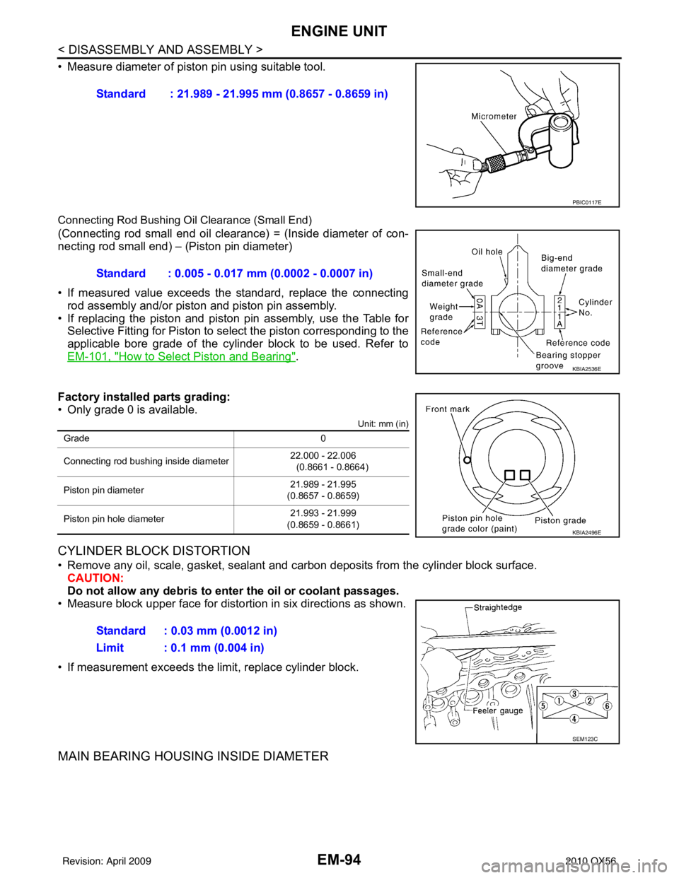
• Measure diameter of piston pin using suitable tool.
Connecting Rod Bushing Oil Clearance (Small End)
(Connecting rod small end oil clearance) = (Inside diameter of con-
necting rod small end) – (Piston pin diameter)
• If measured value exceeds the standard, replace the connectingrod assembly and/or piston and piston pin assembly.
• If replacing the piston and piston pin assembly, use the Table for
Selective Fitting for Piston to select the piston corresponding to the
applicable bore grade of the cylinder block to be used. Refer to
EM-101, "
How to Select Piston and Bearing".
Factory installed parts grading:
• Only grade 0 is available.
Unit: mm (in)
CYLINDER BLOCK DISTORTION
• Remove any oil, scale, gasket, sealant and carbon deposits from the cylinder block surface.
CAUTION:
Do not allow any debris to en ter the oil or coolant passages.
• Measure block upper face for distortion in six directions as shown.
• If measurement exceeds the limit, replace cylinder block.
MAIN BEARING HOUSING INSIDE DIAMETER
Standard : 21.989 - 21.995 mm (0.8657 - 0.8659 in)
PBIC0117E
Standard : 0.005 - 0.017 mm (0.0002 - 0.0007 in)
KBIA2536E
Grade 0
Connecting rod bushing inside diameter 22.000 - 22.006
(0.8661 - 0.8664)
Piston pin diameter 21.989 - 21.995
(0.8657 - 0.8659)
Piston pin hole diameter 21.993 - 21.999
(0.8659 - 0.8661)
KBIA2496E
Standard : 0.03 mm (0.0012 in)
Limit : 0.1 mm (0.004 in)
SEM123C
Revision: April 20092010 QX56
Page 1955 of 4210
EM-104
< DISASSEMBLY AND ASSEMBLY >
HOW TO SELECT PISTON AND BEARING
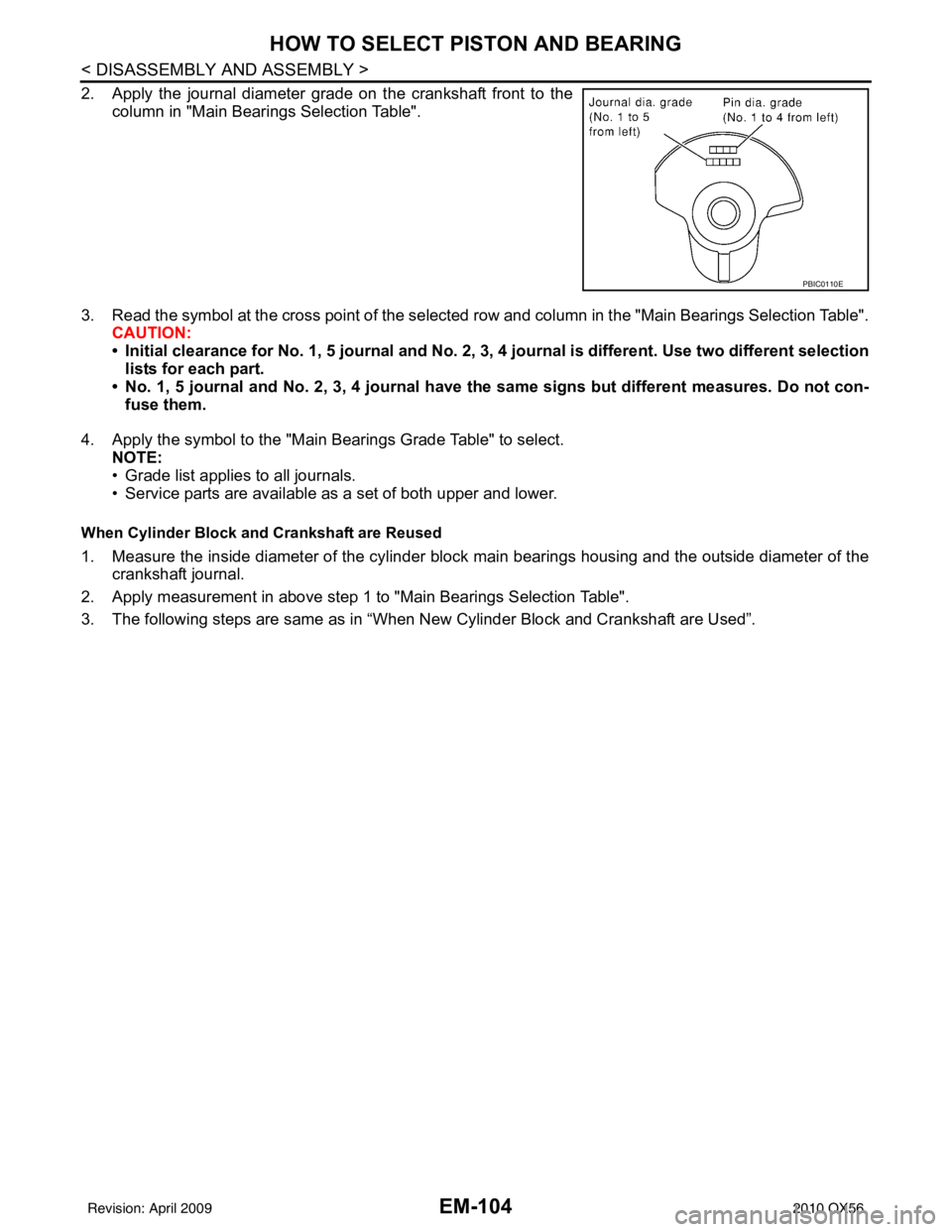
2. Apply the journal diameter grade on the crankshaft front to thecolumn in "Main Bearings Selection Table".
3. Read the symbol at the cross point of the selected row and column in the "Main Bearings Selection Table".
CAUTION:
• Initial clearance for No. 1, 5 journal and No. 2, 3, 4 journal is different. Use two different selection
lists for each part.
• No. 1, 5 journal and No. 2, 3, 4 journal have the same signs but different measures. Do not con-
fuse them.
4. Apply the symbol to the "Main Bearings Grade Table" to select. NOTE:
• Grade list applies to all journals.
• Service parts are available as a set of both upper and lower.
When Cylinder Block and Crankshaft are Reused
1. Measure the inside diameter of the cylinder block main bearings housing and the outside diameter of the
crankshaft journal.
2. Apply measurement in above step 1 to "Main Bearings Selection Table".
3. The following steps are same as in “When New Cylinder Block and Crankshaft are Used”.
PBIC0110E
Revision: April 20092010 QX56