upper INFINITI QX56 2010 Factory Repair Manual
[x] Cancel search | Manufacturer: INFINITI, Model Year: 2010, Model line: QX56, Model: INFINITI QX56 2010Pages: 4210, PDF Size: 81.91 MB
Page 2258 of 4210
SERVICE INFORMATION FOR ELECTRICAL INCIDENTGI-35
< BASIC INSPECTION >
C
DE
F
G H
I
J
K L
M B
GI
N
O P
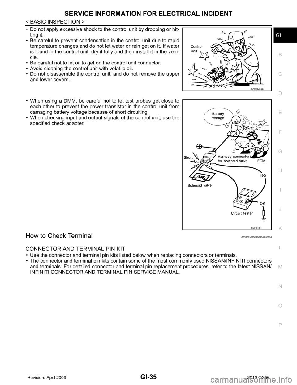
• Do not apply excessive shock to the control unit by dropping or hit- ting it.
• Be careful to prevent condensation in the control unit due to rapid
temperature changes and do not let water or rain get on it. If water
is found in the control unit, dry it fully and then install it in the vehi-
cle.
• Be careful not to let oil to get on the control unit connector.
• Avoid cleaning the control unit with volatile oil.
• Do not disassemble the control unit, and do not remove the upper and lower covers.
• When using a DMM, be careful not to let test probes get close to each other to prevent the power transistor in the control unit from
damaging battery voltage because of short circuiting.
• When checking input and output signals of the control unit, use the specified check adapter.
How to Check TerminalINFOID:0000000005149606
CONNECTOR AND TERMINAL PIN KIT
• Use the connector and terminal pin kits listed below when replacing connectors or terminals.
• The connector and terminal pin kits contain some of the most commonly used NISSAN/INFINITI connectors
and terminals. For detailed connector and terminal pin r eplacement procedures, refer to the latest NISSAN/
INFINITI CONNECTOR AND TERMINAL PIN SERVICE MANUAL.
SAIA0255E
SEF348N
Revision: April 20092010 QX56
Page 2289 of 4210

GW-18
< ON-VEHICLE REPAIR >
REAR DOOR GLASS AND REGULATOR
REAR DOOR GLASS AND REGULATOR
Removal and InstallationINFOID:0000000005147162
REAR DOOR GLASS
Removal
1. Remove the rear door finisher. Refer to INT-11, "Removal and Installation".
2. Position aside the vapor shield.
3. Temporarily reconnect the power window switch.
4. Operate the power window switch to raise/lower the door win- dow until the glass bolts can be seen.
5. Partially remove the inside seal.
6. Remove the glass run from the partition glass.
7. Remove the partition sash bolt (lower) and screw (upper) to remove the sash.
8. Remove the glass bolts and glass.
Installation
Installation is in the reverse order of removal.
Fitting Inspection
• Check that the glass is securely fit into the glass run groove.
• Lower the glass slightly [approximately 10 to 20 mm (0.39 to 0.79 in)], and check that the clearance to the
sash is parallel. If the clearance between the glass and sash is not parallel, loosen the regulator bolts, guide
rail bolts, and glass and carrier plate bolts to correct the glass position.
REAR DOOR GLASS REGULATOR
WIIA0942E
SIIA0290E
Glass bolts : 6.1 N·m (0.62 kg-m, 54 in-lb)
Revision: April 20092010 QX56
Page 2292 of 4210
SIDE WINDOW GLASSGW-21
< ON-VEHICLE REPAIR >
C
DE
F
G H
I
J
L
M A
B
GW
N
O P
SIDE WINDOW GLASS
Removal and InstallationINFOID:0000000005147163
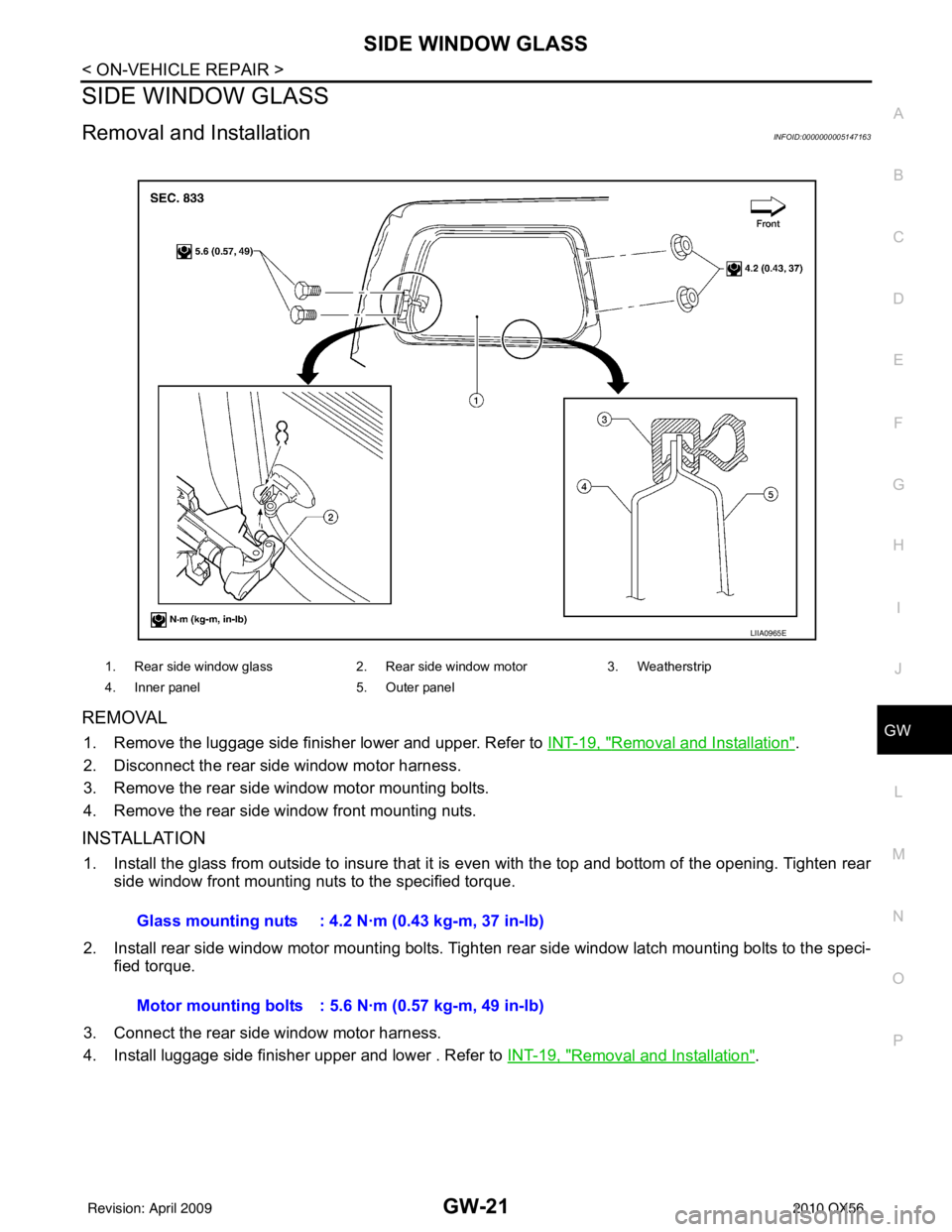
REMOVAL
1. Remove the luggage side finisher lower and upper. Refer to INT-19, "Removal and Installation".
2. Disconnect the rear side window motor harness.
3. Remove the rear side window motor mounting bolts.
4. Remove the rear side window front mounting nuts.
INSTALLATION
1. Install the glass from outside to insure that it is even with the top and bottom of the opening. Tighten rear side window front mounting nuts to the specified torque.
2. Install rear side window motor mounting bolts. Tighten rear side window latch mounting bolts to the speci-
fied torque.
3. Connect the rear side window motor harness.
4. Install luggage side finisher upper and lower . Refer to INT-19, "
Removal and Installation".
1. Rear side window glass2. Rear side window motor3. Weatherstrip
4. Inner panel 5. Outer panel
LIIA0965E
Glass mounting nuts : 4.2 N·m (0.43 kg-m, 37 in-lb)
Motor mounting bolts : 5.6 N·m (0.57 kg-m, 49 in-lb)
Revision: April 20092010 QX56
Page 2453 of 4210
![INFINITI QX56 2010 Factory Repair Manual INSUFFICIENT COOLINGHAC-113
< SYMPTOM DIAGNOSIS > [AUTOMATIC AIR CONDITIONER]
C
D
E
F
G H
J
K L
M A
B
HAC
N
O P
dard (usual) pressure, however, differs from vehicle to vehicle, refer to above table (A INFINITI QX56 2010 Factory Repair Manual INSUFFICIENT COOLINGHAC-113
< SYMPTOM DIAGNOSIS > [AUTOMATIC AIR CONDITIONER]
C
D
E
F
G H
J
K L
M A
B
HAC
N
O P
dard (usual) pressure, however, differs from vehicle to vehicle, refer to above table (A](/img/42/57032/w960_57032-2452.png)
INSUFFICIENT COOLINGHAC-113
< SYMPTOM DIAGNOSIS > [AUTOMATIC AIR CONDITIONER]
C
D
E
F
G H
J
K L
M A
B
HAC
N
O P
dard (usual) pressure, however, differs from vehicle to vehicle, refer to above table (Ambient air temperature-
to-operating pressure table).
Both High- and Low-pressure Sides are Too High
High-pressure Side is Too High and Low-pressure Side is Too Low
High-pressure Side is Too Low and Low-pressure Side is Too High
Gauge indication Refrigerant cycleProbable causeCorrective action
Both high- and low-pressure sides
are too high. Pressure is reduced soon af-
ter water is splashed on con-
denser.
Excessive refrigerant charge in
refrigeration cycle
Reduce refrigerant until speci-
fied pressure is obtained.
Air suction by cooling fan is in-
sufficient. Insufficient condenser cooling
performance
↓
1. Condenser fins are
clogged.
2. Improper fan rotation of
cooling fan • Clean condenser.
• Check and repair cooling fan
if necessary.
• Low-pressure pipe is not cold.
• When compressor is
stopped high-pressure val-
ue quickly drops by approx-
imately 196 kPa (2 kg/cm
2 ,
28 psi). It then decreases
gradually thereafter. Poor heat exchange in con-
denser
(After compressor operation
stops, high-pressure decreas-
es too slowly.)
↓
Air in refrigeration cycle
Evacuate and recharge system.
Engine tends to overheat. Engine cooling systems mal-
function. Check and repair engine cool-
ing system.
• An area of the low-pressure pipe is colder than areas
near the evaporator outlet.
• Plates are sometimes cov- ered with frost. • Excessive liquid refrigerant
on low-pressure side
• Excessive refrigerant dis-
charge flow
• Expansion valve is open a lit- tle compared with the speci-
fication.
↓
Improper expansion valve ad-
justment Replace expansion valve.
AC359A
Gauge indication
Refrigerant cycleProbable causeCorrective action
High-pressure side is too high and
low-pressure side is too low. Upper side of condenser and
high-pressure side are hot,
however, liquid tank is not so
hot.High-pressure tube or parts lo-
cated between compressor
and condenser are clogged or
crushed.
• Check and repair or replace
malfunctioning parts.
• Check oil for contamination.
AC360A
Revision: April 20092010 QX56
Page 2566 of 4210
INT-14
< ON-VEHICLE REPAIR >
BODY SIDE TRIM
BODY SIDE TRIM
Removal and InstallationINFOID:0000000005147350
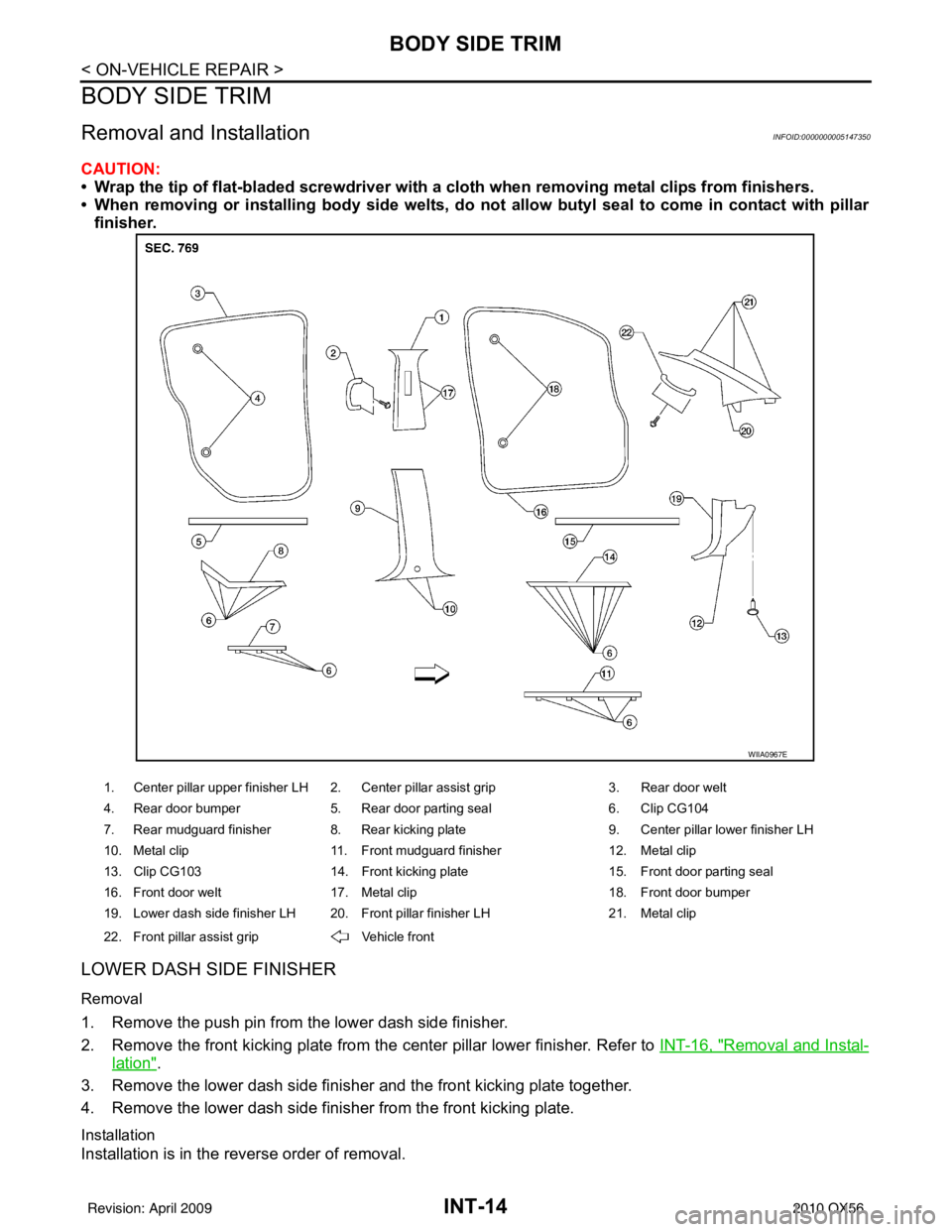
CAUTION:
• Wrap the tip of flat-bladed screwdriver with a cloth when removing metal clips from finishers.
• When removing or installing body side welts, do not allow butyl seal to come in contact with pillar
finisher.
LOWER DASH SIDE FINISHER
Removal
1. Remove the push pin from the lower dash side finisher.
2. Remove the front kicking plate from the center pillar lower finisher. Refer to INT-16, "
Removal and Instal-
lation".
3. Remove the lower dash side finisher and the front kicking plate together.
4. Remove the lower dash side finisher from the front kicking plate.
Installation
Installation is in the reverse order of removal.
1. Center pillar upper finisher LH 2. Center pillar assist grip 3. Rear door welt
4. Rear door bumper 5. Rear door parting seal 6. Clip CG104
7. Rear mudguard finisher 8. Rear kicking plate 9. Center pillar lower finisher LH
10. Metal clip 11. Front mudguard finisher 12. Metal clip
13. Clip CG103 14. Front kicking plate 15. Front door parting seal
16. Front door welt 17. Metal clip 18. Front door bumper
19. Lower dash side finisher LH 20. Front pillar finisher LH 21. Metal clip
22. Front pillar assist grip Vehicle front
WIIA0967E
Revision: April 20092010 QX56
Page 2567 of 4210

BODY SIDE TRIMINT-15
< ON-VEHICLE REPAIR >
C
DE
F
G H
I
K L
M A
B
INT
N
O P
CENTER PILLAR LOWER FINISHER
Removal
CAUTION:
Disconnect both terminals from battery in advance.
1. Disconnect the battery negative terminal.
2. Remove seat belt anchor. Refer to SB-14, "
Removal and Installation".
• On RH side, disconnect seat belt tension sensor.
3. Remove front and rear kicking plates.
4. Remove center pillar lower finisher.
Installation
Installation is in the reverse order of removal.
CENTER PILLAR UPPER FINISHER
Removal
1. Remove front and rear door welts.
2. Disconnect the battery negative terminal.
3. Remove seat belt shoulder anchor and D-ring. Refer to SB-14, "
Removal and Installation".
4. Remove front and rear kicking plates.
5. Remove center pillar lower finisher.
6. Remove center pillar assist grip.
7. Remove center pillar upper finisher.
Installation
Installation is in the reverse order of removal.
FRONT PILLAR FINISHER
Removal
1. Remove the assist grip.
2. Remove the front pillar finisher.
Installation
Installation is in the reverse order of removal.
KICKING PLATES
Removal
Release the clips and remove the front and/or rear kicking plates.
Installation
Installation is in the reverse order of removal.
MUDGUARD FINISHERS
Removal
Release the clips and remove the front and/or rear mudguard finishers.
Installation
Installation is in the reverse order of removal.
DOOR PARTING SEALS
Removal
1. Open front and/or rear doors fully.
2. Release clips and remove parting seals.
Installation
Installation is in the reverse order of removal.
Revision: April 20092010 QX56
Page 2571 of 4210
LUGGAGE FLOOR TRIMINT-19
< ON-VEHICLE REPAIR >
C
DE
F
G H
I
K L
M A
B
INT
N
O P
LUGGAGE FLOOR TRIM
Removal and InstallationINFOID:0000000005147353
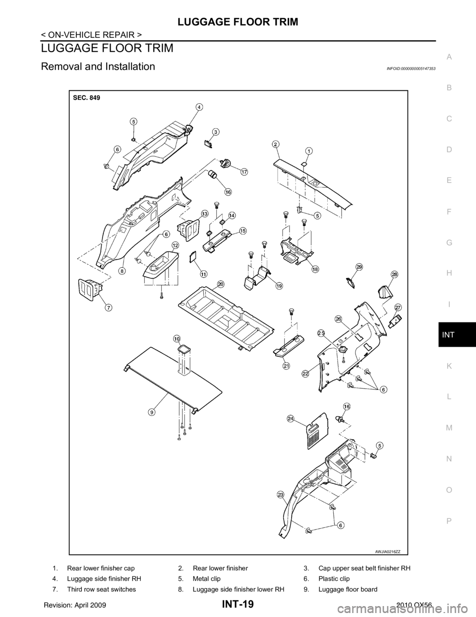
1. Rear lower finisher cap 2. Rear lower finisher3. Cap upper seat belt finisher RH
4. Luggage side finisher RH 5. Metal clip6. Plastic clip
7. Third row seat switches 8. Luggage side finisher lower RH 9. Luggage floor board
AWJIA0216ZZ
Revision: April 20092010 QX56
Page 2572 of 4210
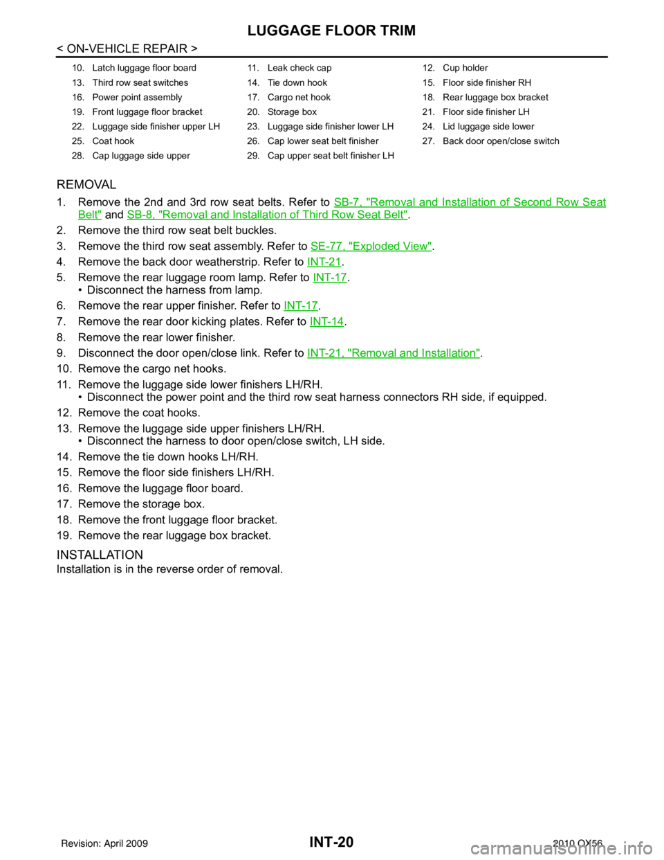
INT-20
< ON-VEHICLE REPAIR >
LUGGAGE FLOOR TRIM
REMOVAL
1. Remove the 2nd and 3rd row seat belts. Refer to SB-7, "Removal and Installation of Second Row Seat
Belt" and SB-8, "Removal and Installation of Third Row Seat Belt".
2. Remove the third row seat belt buckles.
3. Remove the third row seat assembly. Refer to SE-77, "
Exploded View".
4. Remove the back door weatherstrip. Refer to INT-21
.
5. Remove the rear luggage room lamp. Refer to INT-17
.
• Disconnect the harness from lamp.
6. Remove the rear upper finisher. Refer to INT-17
.
7. Remove the rear door kicking plates. Refer to INT-14
.
8. Remove the rear lower finisher.
9. Disconnect the door open/close link. Refer to INT-21, "
Removal and Installation".
10. Remove the cargo net hooks.
11. Remove the luggage side lower finishers LH/RH. • Disconnect the power point and the third row seat harness connectors RH side, if equipped.
12. Remove the coat hooks.
13. Remove the luggage side upper finishers LH/RH. • Disconnect the harness to door open/close switch, LH side.
14. Remove the tie down hooks LH/RH.
15. Remove the floor side finishers LH/RH.
16. Remove the luggage floor board.
17. Remove the storage box.
18. Remove the front luggage floor bracket.
19. Remove the rear luggage box bracket.
INSTALLATION
Installation is in the reverse order of removal.
10. Latch luggage floor board 11. Leak check cap 12. Cup holder
13. Third row seat switches 14. Tie down hook 15. Floor side finisher RH
16. Power point assembly 17. Cargo net hook 18. Rear luggage box bracket
19. Front luggage floor bracket 20. Storage box 21. Floor side finisher LH
22. Luggage side finisher upper LH 23. Luggage side finisher lower LH 24. Lid luggage side lower
25. Coat hook 26. Cap lower seat belt finisher 27. Back door open/close switch
28. Cap luggage side upper 29. Cap upper seat belt finisher LH
Revision: April 20092010 QX56
Page 2573 of 4210
BACK DOOR TRIMINT-21
< ON-VEHICLE REPAIR >
C
DE
F
G H
I
K L
M A
B
INT
N
O P
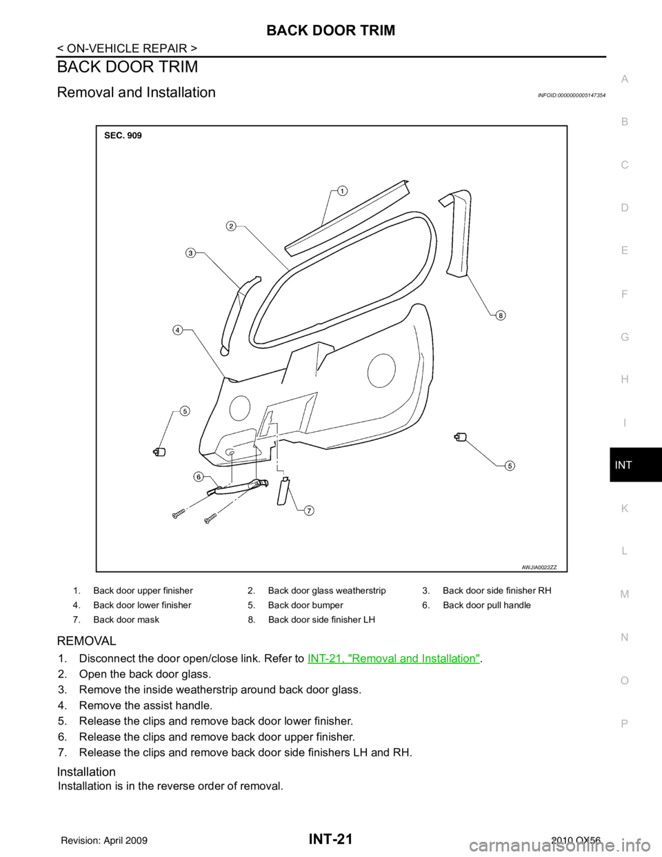
BACK DOOR TRIM
Removal and InstallationINFOID:0000000005147354
REMOVAL
1. Disconnect the door open/close link. Refer to INT-21, "Removal and Installation".
2. Open the back door glass.
3. Remove the inside weatherstrip around back door glass.
4. Remove the assist handle.
5. Release the clips and remove back door lower finisher.
6. Release the clips and remove back door upper finisher.
7. Release the clips and remove back door side finishers LH and RH.
Installation
Installation is in the reverse order of removal.
1. Back door upper finisher 2. Back door glass weatherstrip 3. Back door side finisher RH
4. Back door lower finisher 5. Back door bumper6. Back door pull handle
7. Back door mask 8. Back door side finisher LH
AWJIA0022ZZ
Revision: April 20092010 QX56
Page 2574 of 4210
IP-1
BODY INTERIOR
C
DE
F
G H
I
K L
M
SECTION IP
A
B
IP
N
O P
CONTENTS
INSTRUMENT PANEL
PRECAUTION ....... ........................................2
PRECAUTIONS .............................................. .....2
Precaution for Supplemental Restraint System
(SRS) "AIR BAG" and "SEAT BELT PRE-TEN-
SIONER" ............................................................. ......
2
Precaution Necessary for Steering Wheel Rota-
tion After Battery Disconnect ............................... ......
2
PREPARATION ............................................4
PREPARATION .............................................. .....4
Special Service Tool ........................................... ......4
Commercial Service Tool ..........................................4
SYMPTOM DIAGNOSIS ...............................5
SQUEAK AND RATTLE TROUBLE DIAG-
NOSES ........................ ........................................
5
Work Flow ........................................................... ......5
Generic Squeak and Rattle Troubleshooting ............7
Diagnostic Worksheet ...............................................9
ON-VEHICLE REPAIR .................................11
INSTRUMENT PANEL ASSEMBLY .............. ....11
Exploded View .................................................... ....11
Removal and Installation .........................................12
CLUSTER LID A ............................................. ....14
Exploded View .................................................... ....14
Removal and Installation .........................................14
CLUSTER LID C ...............................................15
Exploded View ..................................................... ....15
Removal and Installation .........................................15
INSTRUMENT LOWER PANEL RH AND
GLOVE BOX .....................................................
17
Exploded View .........................................................17
Removal and Installation .........................................17
INSTRUMENT UPPER PANEL RH ..................18
Exploded View .........................................................18
Removal and Installation .........................................18
A/T FINISHER ...................................................19
Removal and Installation .........................................19
FRONT CENTER CONSOLE ............................20
Exploded View .........................................................20
Removal and Installation .........................................20
REAR CENTER CONSOLE ..............................21
Removal and Installation .........................................21
DISASSEMBLY AND ASSEMBLY ..............22
FRONT CENTER CONSOLE ............................22
Exploded View ..................................................... ....22
Disassembly and Assembly .....................................23
REAR CENTER CONSOLE ..............................24
Exploded View .........................................................24
Disassembly and Assembly .....................................25
Revision: April 20092010 QX56