Oil INFINITI QX56 2010 Factory Service Manual
[x] Cancel search | Manufacturer: INFINITI, Model Year: 2010, Model line: QX56, Model: INFINITI QX56 2010Pages: 4210, PDF Size: 81.91 MB
Page 3664 of 4210
ST-26
< REMOVAL AND INSTALLATION >
POWER STEERING OIL PUMP
POWER STEERING OIL PUMP
Removal and InstallationINFOID:0000000005147874
REMOVAL
1. Drain power steering fluid from reservoir tank.
2. Remove engine room cover. Refer to EM-24, "
Removal and Installation".
3. Remove air duct assembly. Refer to EM-25, "
Removal and Installation".
4. Remove power steering reservoir tank.
5. Remove serpentine drive belt belt from auto tensioner and power steering pump. Refer to EM-13,
"Removal and Installation".
6. Disconnect pressure sensor electrical connector.
7. Remove high pressure and low pressure piping from power steering oil pump. Refer to ST-27
.
8. Remove bolts, then remove power steering pump.
INSTALLATION
Installation is in the reverse order of removal. Refer to ST-27 for tightening torque.
• After installation, bleed air. Refer to ST-13, "
Air Bleeding Hydraulic System".
NOTE:
Belt tension is automatic and requires no adjustment.
Revision: April 20092010 QX56
Page 3665 of 4210

HYDRAULIC LINEST-27
< REMOVAL AND INSTALLATION >
C
DE
F
H I
J
K L
M A
B
ST
N
O P
HYDRAULIC LINE
Removal and InstallationINFOID:0000000005147875
Refer to the following illustration for hydralic line removal.
Installation is in the reverse order of removal.
1. Reservoir tank 2. Suction hose 3. High pressure hose
4. Oil cooler 5. Steering gear assembly 6. Reservoir tank bracket
7. Eye bolt 8. O-rings
AWGIA0115GB
Revision: April 20092010 QX56
Page 3669 of 4210
POWER STEERING GEAR AND LINKAGEST-31
< DISASSEMBLY AND ASSEMBLY >
C
DE
F
H I
J
K L
M A
B
ST
N
O P
POWER STEERING GEAR AND LINKAGE
Disassembly and AssemblyINFOID:0000000005147877
CAUTION:
• Secure steering gear assembly with a vise, using copper plates or something similar to prevent it
from being damaged. Do not grip cylinder with a vise.
• Before performing disassembly, clean steering gear assembly with kerosene. Be careful not to bring
any kerosene into contact with the di scharge and return port connectors.
DISASSEMBLY
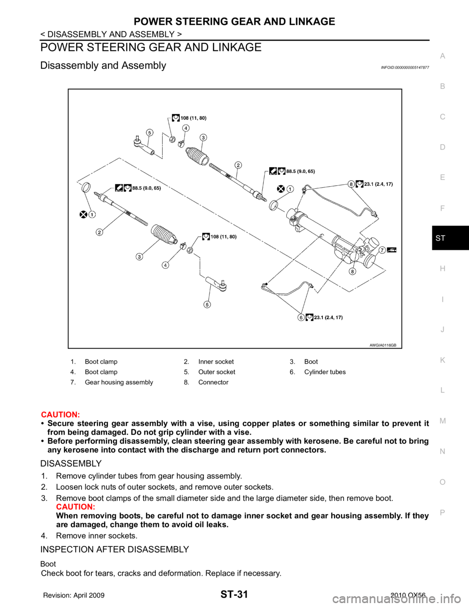
1. Remove cylinder tubes from gear housing assembly.
2. Loosen lock nuts of outer sockets, and remove outer sockets.
3. Remove boot clamps of the small diameter si de and the large diameter side, then remove boot.
CAUTION:
When removing boots, be careful not to damage inner socket and gear housing assembly. If they
are damaged, change th em to avoid oil leaks.
4. Remove inner sockets.
INSPECTION AFTER DISASSEMBLY
Boot
Check boot for tears, cracks and deformation. Replace if necessary.
1. Boot clamp 2. Inner socket3. Boot
4. Boot clamp 5. Outer socket6. Cylinder tubes
7. Gear housing assembly 8. Connector
AWGIA0116GB
Revision: April 20092010 QX56
Page 3672 of 4210
ST-34
< DISASSEMBLY AND ASSEMBLY >
POWER STEERING OIL PUMP
POWER STEERING OIL PUMP
Disassembly and AssemblyINFOID:0000000005147878
INSPECTION BEFORE DISASSEMBLY
Disassemble the power steering oil pump only if the following items are found.
• Deformed or damaged pulley, bracket, connector or suction pipe.
• Oil leakage from the suction pipe or connector.
DISASSEMBLY
NOTE:
Mount the power steering oil pump in a vise as needed.
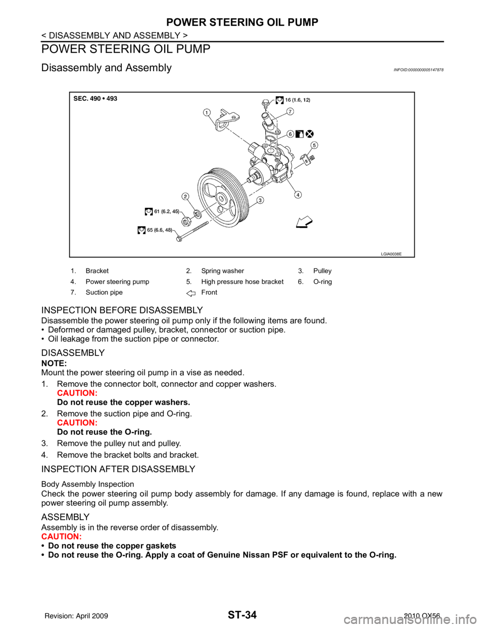
1. Remove the connector bolt, connector and copper washers. CAUTION:
Do not reuse the copper washers.
2. Remove the suction pipe and O-ring. CAUTION:
Do not reuse the O-ring.
3. Remove the pulley nut and pulley.
4. Remove the bracket bolts and bracket.
INSPECTION AFTER DISASSEMBLY
Body Assembly Inspection
Check the power steering oil pump body assembly fo r damage. If any damage is found, replace with a new
power steering oil pump assembly.
ASSEMBLY
Assembly is in the reverse order of disassembly.
CAUTION:
• Do not reuse the copper gaskets
• Do not reuse the O-ring. Apply a coat of Ge nuine Nissan PSF or equivalent to the O-ring.
1. Bracket 2. Spring washer3. Pulley
4. Power steering pump 5. High pressure hose bracket 6. O-ring
7. Suction pipe Front
LGIA0038E
Revision: April 20092010 QX56
Page 3675 of 4210
SERVICE DATA AND SPECIFICATIONS (SDS)ST-37
< SERVICE DATA AND SPECIFICATIONS (SDS)
C
DE
F
H I
J
K L
M A
B
ST
N
O P
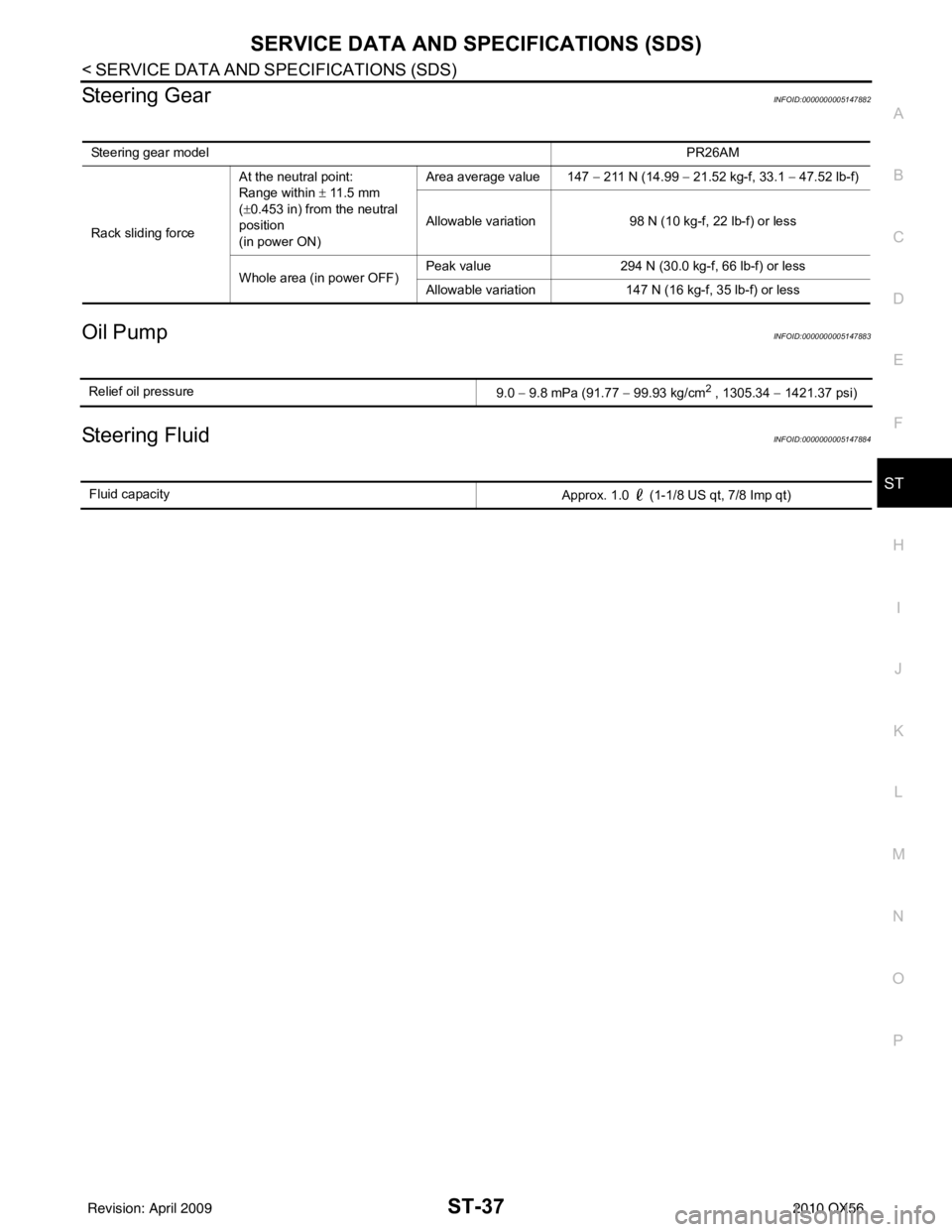
Steering GearINFOID:0000000005147882
Oil PumpINFOID:0000000005147883
Steering FluidINFOID:0000000005147884
Steering gear model PR26AM
Rack sliding force At the neutral point:
Range within ±
11.5 mm
(± 0.453 in) from the neutral
position
(in power ON) Area average value 147
− 211 N (14.99 − 21.52 kg-f, 33.1 − 47.52 lb-f)
Allowable variation 98 N (10 kg-f, 22 lb-f) or less
Whole area (in power OFF) Peak value
294 N (30.0 kg-f, 66 lb-f) or less
Allowable variation 147 N (16 kg-f, 35 lb-f) or less
Relief oil pressure
9.0 − 9.8 mPa (91.77 − 99.93 kg/cm2 , 1305.34 − 1421.37 psi)
Fluid capacity
Approx. 1.0 (1-1/8 US qt, 7/8 Imp qt)
Revision: April 20092010 QX56
Page 3699 of 4210

TM-4
STALL TEST ....................................................155
Inspection and Judgment .................................... ..155
LINE PRESSURE TEST ..................................157
Inspection and Judgment .................................... ..157
ROAD TEST .....................................................159
Description ........................................................... ..159
Check Before Engine Is Started ............................159
Check At Idle ....................................................... ..159
Cruise Test - Part 1 ...............................................160
Cruise Test - Part 2 ...............................................162
Cruise Test - Part 3 ...............................................162
Vehicle Speed When Shifting Gears .....................163
Vehicle Speed When Performing and Releasing
Complete Lock-up .................................................
163
A/T POSITION .................................................164
Adjustment of A/T Position .................................. ..164
Checking of A/T Position .......................................164
ON-VEHICLE REPAIR ...............................165
SHIFT CONTROL SYSTEM ........................... .165
A/T Shift Selector Removal and Installation ..........165
AIR BREATHER HOSE .................................. .166
Removal and Installation ..................................... ..166
OIL PAN ...........................................................170
Oil Pan ................................................................. ..170
CONTROL VALVE WITH TCM ........................172
Control Valve with TCM and A/T Fluid Tempera-
ture Sensor 2 and Plug ........................................ ..
172
REAR OIL SEAL ..............................................184
Rear Oil Seal ....................................................... ..184
FLUID COOLER SYSTEM ...............................185
Exploded View ..................................................... ..185
Removal and Installation .......................................185
REMOVAL AND INSTALLATION ..............186
TRANSMISSION ASSEMBLY ........................ .186
Removal and Installation (2WD) .......................... .186
Removal and Installation (4WD) ...........................188
DISASSEMBLY AND ASSEMBLY ...........192
OVERHAUL ......................................................192
Component .......................................................... .192
Oil Channel ...........................................................199
Location of Adjusting Shims, Needle Bearings,
Thrust Washers and Snap Rings ......................... .
201
DISASSEMBLY .............................................. ..204
Disassembly ......................................................... .204
REPAIR FOR COMPONENT PARTS ..............223
Oil Pump .............................................................. .223
Front Sun Gear, 3rd One-Way Clutch ...................225
Front Carrier, Input Clutch, Rear Internal Gear .....227
Mid Sun Gear, Rear Sun Gear, High and Low Re-
verse Clutch Hub ................................................. .
232
High and Low Reverse Clutch ..............................237
Direct Clutch .........................................................239
ASSEMBLY .................................................... ..242
Assembly (1) ........................................................ .242
Adjustment ............................................................255
Assembly (2) .........................................................257
SERVICE DATA AND SPECIFICATIONS
(SDS) ........ .................................................
265
SERVICE DATA AND SPECIFICATIONS
(SDS) .............................................................. ..
265
General Specification ........................................... .265
Vehicle Speed at Which Gear Shifting Occurs .....265
Vehicle Speed at Which Lock-up Occurs/Releas-
es ......................................................................... .
266
Stall Speed ............................................................266
Line Pressure ........................................................266
Input Speed Sensor ..............................................266
Output Speed Sensor ...........................................266
Reverse Brake ......................................................266
Total End Play .......................................................267
Torque Converter ..................................................267
Revision: April 20092010 QX56
Page 3703 of 4210
TM-8
< FUNCTION DIAGNOSIS >
A/T CONTROL SYSTEM
FUNCTION DIAGNOSIS
A/T CONTROL SYSTEM
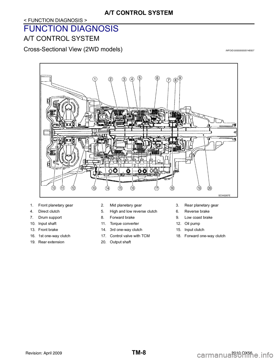
Cross-Sectional View (2WD models)INFOID:0000000005148507
1. Front planetary gear2. Mid planetary gear 3. Rear planetary gear
4. Direct clutch 5. High and low reverse clutch 6. Reverse brake
7. Drum support 8. Forward brake 9. Low coast brake
10. Input shaft 11. Torque converter 12. Oil pump
13. Front brake 14. 3rd one-way clutch 15. Input clutch
16. 1st one-way clutch 17. Control valve with TCM 18. Forward one-way clutch
19. Rear extension 20. Output shaft
SCIA5267E
Revision: April 20092010 QX56
Page 3704 of 4210

A/T CONTROL SYSTEMTM-9
< FUNCTION DIAGNOSIS >
CEF
G H
I
J
K L
M A
B
TM
N
O P
Cross-Sectional View (4WD models)INFOID:0000000005148508
Shift MechanismINFOID:0000000005148509
The automatic transmission uses compact triple planet ary gear systems to improve power-transmission effi-
ciency, simplify construction and reduce weight.
It also employs an optimum shift control and super wide gear ratios. They improve starting performance and
acceleration during medium and high-speed operation.
CONSTRUCTION
1. Front planetary gear 2. Mid planetary gear 3. Rear planetary gear
4. Direct clutch 5. High and low reverse clutch 6. Reverse brake
7. Drum support 8. Forward brake 9. Low coast brake
10. Input shaft 11. Torque converter 12. Oil pump
13. Front brake 14. 3rd one-way clutch 15. Input clutch
16. 1st one-way clutch 17. Control valve with TCM 18. Forward one-way clutch
19. Adapter case 20. Output shaft
SCIA5268E
Revision: April 20092010 QX56
Page 3718 of 4210
A/T CONTROL SYSTEMTM-23
< FUNCTION DIAGNOSIS >
CEF
G H
I
J
K L
M A
B
TM
N
O P
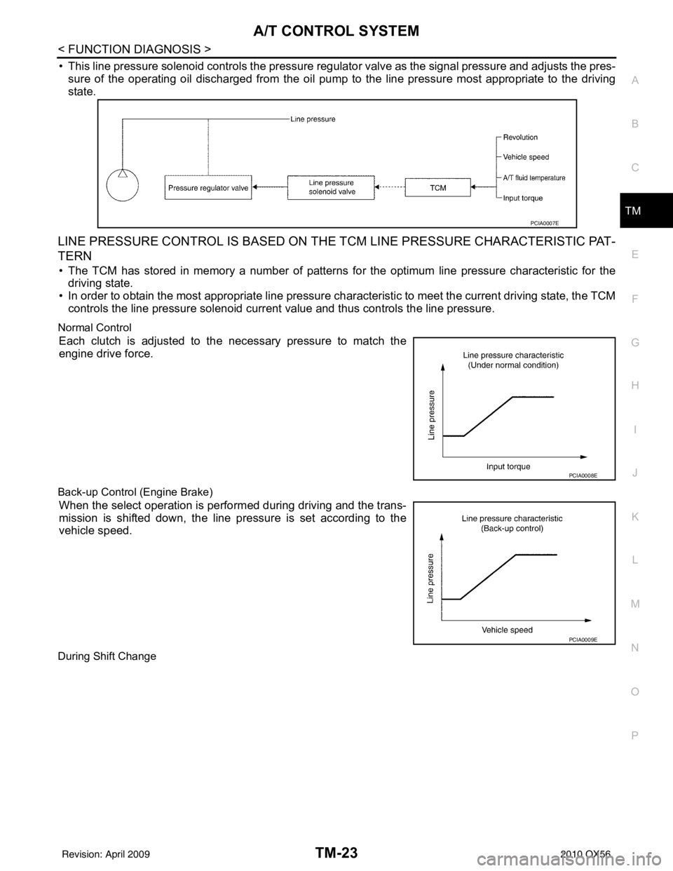
• This line pressure solenoid controls the pressure regulat or valve as the signal pressure and adjusts the pres-
sure of the operating oil discharged from the oil pump to the line pressure most appropriate to the driving
state.
LINE PRESSURE CONTROL IS BASED ON THE TCM LINE PRESSURE CHARACTERISTIC PAT-
TERN
• The TCM has stored in memory a number of patterns fo r the optimum line pressure characteristic for the
driving state.
• In order to obtain the most appropriate line pressure char acteristic to meet the current driving state, the TCM
controls the line pressure solenoid current value and thus controls the line pressure.
Normal Control
Each clutch is adjusted to the necessary pressure to match the
engine drive force.
Back-up Control (Engine Brake)
When the select operation is performed during driving and the trans-
mission is shifted down, the line pressure is set according to the
vehicle speed.
During Shift Change
PCIA0007E
PCIA0008E
PCIA0009E
Revision: April 20092010 QX56
Page 3719 of 4210

TM-24
< FUNCTION DIAGNOSIS >
A/T CONTROL SYSTEM
The necessary and adequate line pressure for shift change is set.
For this reason, line pressure pattern setting corresponds to input
torque and gearshift selection. Also, line pressure characteristic is
set according to engine speed, during engine brake operation.
At Low Fluid Temperature
When the A/T fluid temperature drops below the prescribed tempera-
ture, in order to speed up the action of each friction element, the line
pressure is set higher than the normal line pressure characteristic.
Shift ControlINFOID:0000000005148514
The clutch pressure control solenoid is controlled by the signals from the switches and sensors. Thus, the
clutch pressure is adjusted to be appropriate to the engine load state and vehicle driving state. It becomes
possible to finely control the clutch hydraulic pressure with high precision and a smoother shift change charac-
teristic is attained.
SHIFT CHANGE
The clutch is controlled with the optimum timing and oil pressure by the engine speed, engine torque informa-
tion, etc.
Shift Change System Diagram
PCIA0010E
PCIA0011E
PCIA0012E
Revision: April 20092010 QX56