Oil INFINITI QX56 2010 Factory Service Manual
[x] Cancel search | Manufacturer: INFINITI, Model Year: 2010, Model line: QX56, Model: INFINITI QX56 2010Pages: 4210, PDF Size: 81.91 MB
Page 3464 of 4210
![INFINITI QX56 2010 Factory Service Manual IPDM E/R (INTELLIGENT POWER DISTRIBUTION MODULE ENGINE ROOM)
SEC-113
< ECU DIAGNOSIS > [WITH INTELLIGENT KEY SYSTEM]
C
D
E
F
G H
I
J
L
M A
B
SEC
N
O P
*: When horn reminder is ON
Fail SafeINFOID:00000 INFINITI QX56 2010 Factory Service Manual IPDM E/R (INTELLIGENT POWER DISTRIBUTION MODULE ENGINE ROOM)
SEC-113
< ECU DIAGNOSIS > [WITH INTELLIGENT KEY SYSTEM]
C
D
E
F
G H
I
J
L
M A
B
SEC
N
O P
*: When horn reminder is ON
Fail SafeINFOID:00000](/img/42/57032/w960_57032-3463.png)
IPDM E/R (INTELLIGENT POWER DISTRIBUTION MODULE ENGINE ROOM)
SEC-113
< ECU DIAGNOSIS > [WITH INTELLIGENT KEY SYSTEM]
C
D
E
F
G H
I
J
L
M A
B
SEC
N
O P
*: When horn reminder is ON
Fail SafeINFOID:0000000005282721
CAN COMMUNICATION CONTROL
When CAN communication with ECM and BCM is impossible, IPDM E/R performs fail-s afe control. After CAN
communication recovers normally, it also returns to normal control.
If No CAN Communication Is Available With ECM
If No CAN Communication Is Available With BCM
IGNITION RELAY MALFUNCTION DETECTION FUNCTION
• IPDM E/R monitors the voltage at the contact circuit and excitation coil circuit of the ignition relay inside it.
• IPDM E/R judges the ignition relay error if the voltage differs between the contact circuit and the excitation coil circuit.
• If the ignition relay cannot turn OFF due to contact seizure, it activates the tail lamp relay for 10 minutes to
alert the user to the ignition relay malfunction when the ignition switch is turned OFF.
NOTE:
The tail lamp turns OFF when the ignition switch is turned ON.
FRONT WIPER CONTROL
IPDM E/R detects front wiper stop posit ion by a front wiper auto stop signal.
60 B/WRear window defog-
ger relay
OutputON or
START Rear defogger switch ON
Battery voltage
Rear defogger switch OFF 0V
61 BR Fuse 32
(With trailer tow) Output OFF
—Battery voltage
Te r m i n a l
Wire
color Signal name Signal
input/
output Measuring condition
Reference value(Approx.)
Igni-
tion
switch Operation or condition
Control part
Fail-safe in operation
Cooling fan • Turns ON the cooling fan relay when the ignition switch is turned ON
• Turns OFF the cooling fan relay when the ignition switch is turned OFF
Control part
Fail-safe in operation
Headlamp • Turns ON the headlamp low relay when the ignition switch is turned ON
• Turns OFF the headlamp low relay when the ignition switch is turned OFF
• Headlamp high LH/RH relays OFF
•Parking lamps
• License plate lamps
• Tail lamps • Turns ON the tail lamp relay when the ignition switch is turned ON
• Turns OFF the tail lamp relay when the ignition switch is turned OFF
Front wiper • The status just before activation of fail-safe control is maintained until the ignition
switch is turned OFF while the front wiper is operating at LO or HI speed.
• The wiper is operated at LO speed until the ignition switch is turned OFF if the fail-
safe control is activated while the front wipe r is set in the INT mode and the front wiper
motor is operating.
Rear window defogger Rear window defogger relay OFF
A/C compressor A/C relay OFF
Front fog lamps Front fog lamp relay OFF
Ignition switch Ignition relayTail lamp relay
ON ON —
OFF OFF —
Revision: April 20092010 QX56
Page 3529 of 4210

SR-6
< ON-VEHICLE REPAIR >
DRIVER AIR BAG MODULE
• Replace the air bag module if it has been dropped or sus-
tained an impact.
• Do not allow oil, grease or water to come in contact with the
air bag module.
INSTALLATION
Installation is in the reverse order of removal.
• If driver air bag module is being replaced due to deployment, spiral cable must also be replaced. Refer toSR-7, "
Removal and Installation".
• For removal/installation of the direct-connect SRS connectors, refer to SRC-9, "
Direct-connect SRS Compo-
nent Connectors".
• After the work is completed, perform self-diagnosis to check that no malfunction is detected. Refer to SRC-
13, "SRS Operation Check".
SBF814E
Revision: April 20092010 QX56
Page 3534 of 4210
FRONT PASSENGER AIR BAG MODULESR-11
< ON-VEHICLE REPAIR >
C
DE
F
G
I
J
K L
M A
B
SR
N
O P
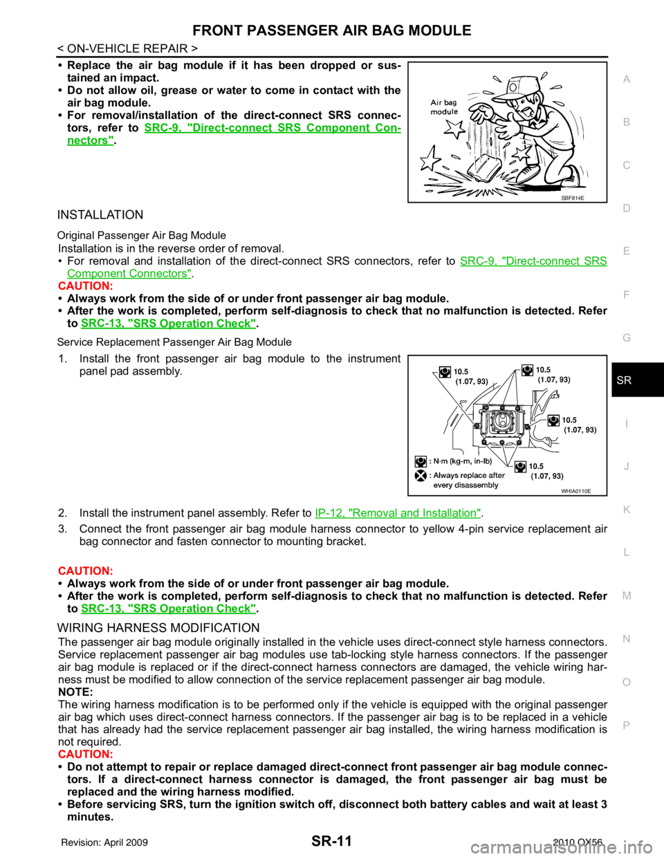
• Replace the air bag module if it has been dropped or sus-
tained an impact.
• Do not allow oil, grease or water to come in contact with the
air bag module.
• For removal/installation of the direct-connect SRS connec- tors, refer to SRC-9, "
Direct-connect SRS Component Con-
nectors".
INSTALLATION
Original Passenger Air Bag Module
Installation is in the reverse order of removal.
• For removal and installation of the direct-connect SRS connectors, refer to SRC-9, "
Direct-connect SRS
Component Connectors".
CAUTION:
• Always work from the side of or under front passenger air bag module.
• After the work is completed, perform self-diagnosi s to check that no malfunction is detected. Refer
to SRC-13, "
SRS Operation Check".
Service Replacement Passenger Air Bag Module
1. Install the front passenger air bag module to the instrument
panel pad assembly.
2. Install the instrument panel assembly. Refer to IP-12, "
Removal and Installation".
3. Connect the front passenger air bag module harness connector to yellow 4-pin service replacement air bag connector and fasten connector to mounting bracket.
CAUTION:
• Always work from the side of or under front passenger air bag module.
• After the work is completed, perform self-diagnosi s to check that no malfunction is detected. Refer
to SRC-13, "
SRS Operation Check".
WIRING HARNESS MODIFICATION
The passenger air bag module originally installed in t he vehicle uses direct-connect style harness connectors.
Service replacement passenger air bag modules use t ab-locking style harness connectors. If the passenger
air bag module is replaced or if the direct-connect harness connectors are damaged, the vehicle wiring har-
ness must be modified to allow connection of t he service replacement passenger air bag module.
NOTE:
The wiring harness modification is to be performed only if the vehicle is equipped with the original passenger
air bag which uses direct-connect harness connectors. If the passenger air bag is to be replaced in a vehicle
that has already had the service replacement passenger air bag installed, the wiring harness modification is
not required.
CAUTION:
• Do not attempt to repair or replace damaged dir ect-connect front passenger air bag module connec-
tors. If a direct-connect harness connector is damaged, the front passenger air bag must be
replaced and the wiri ng harness modified.
• Before servicing SRS, turn the igni tion switch off, disconnect both battery cables and wait at least 3
minutes.
SBF814E
WHIA0110E
Revision: April 20092010 QX56
Page 3536 of 4210
SIDE CURTAIN AIR BAG MODULESR-13
< ON-VEHICLE REPAIR >
C
DE
F
G
I
J
K L
M A
B
SR
N
O P
SIDE CURTAIN AIR BAG MODULE
Removal and InstallationINFOID:0000000005147760
REMOVAL
CAUTION:
• Do not attempt to repair or replace damaged direct-connect SRS component connectors. If a direct- connect harness connector is damage d, the harness must be replaced.
• Before servicing the SRS, turn the ignition switch off, disconnect both battery terminals and wait at
least three minutes.
• When servicing the SRS, do not work from directly in front of air bag module.
• Do not insert any foreign objects (screwdriver, etc.) into air bag module or harness connectors.
• Do not disassemble air bag module.
• Do not expose the air bag modu le to temperatures exceeding 90°C (194 °F).
• Replace side curtain air bag modu le if it has been dropped or
sustained an impact.
• Do not allow oil, grease or water to come in contact with the
air bag module.
1. Disconnect both the negative and positive battey terminals, then wait at least three minutes.
2. Remove headlining. Refer to INT-17, "
Removal and Installation".
3. Disconnect front and rear side curtain air bag module connec- tors.
• For removal/installation of the direct-connect SRS connectors,
refer to SRC-9, "
Direct-connect SRS Component Connectors".
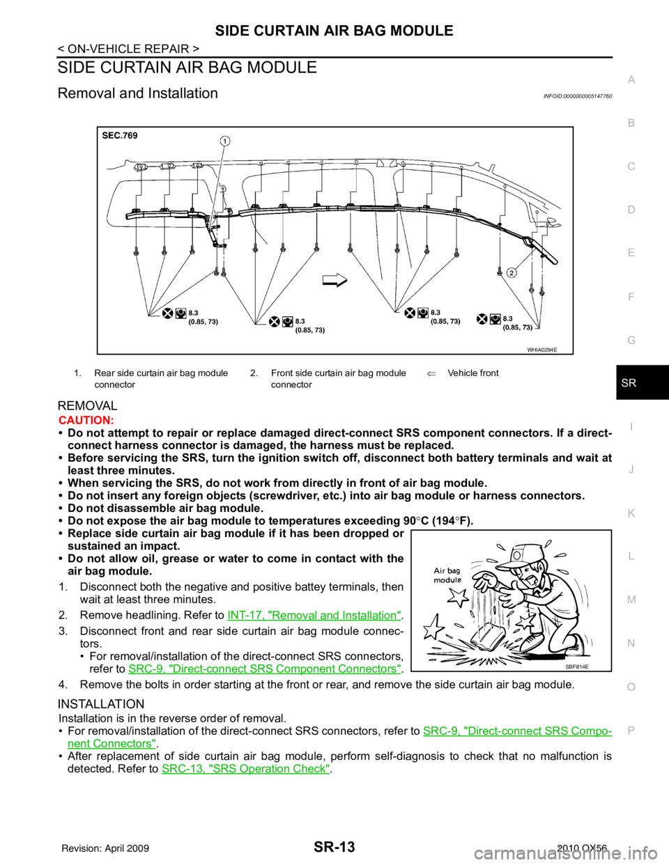
4. Remove the bolts in order starting at the front or rear, and remove the side curtain air bag module.
INSTALLATION
Installation is in the reverse order of removal.
• For removal/installation of the direct-connect SRS connectors, refer to SRC-9, "
Direct-connect SRS Compo-
nent Connectors".
• After replacement of side curtain air bag module, per form self-diagnosis to check that no malfunction is
detected. Refer to SRC-13, "
SRS Operation Check".
1. Rear side curtain air bag module
connector 2. Front side curtain air bag module
connector ⇐
Vehicle front
WHIA0294E
SBF814E
Revision: April 20092010 QX56
Page 3639 of 4210

ST-1
STEERING
C
DE
F
H I
J
K L
M
SECTION ST
A
B
ST
N
O P
CONTENTS
STEERING SYSTEM
PRECAUTION ....... ........................................3
PRECAUTIONS .............................................. .....3
Precaution for Supplemental Restraint System
(SRS) "AIR BAG" and "SEAT BELT PRE-TEN-
SIONER" ............................................................. ......
3
Precaution Necessary for Steering Wheel Rota-
tion After Battery Disconnect ............................... ......
3
PREPARATION ............................................5
PREPARATION .............................................. .....5
Special Service Tool ........................................... ......5
Commercial Service Tool ..........................................6
FUNCTION DIAGNOSIS ...............................7
HEATED STEERING WHEEL ........................ .....7
System Diagram .................................................. ......7
System Description ...................................................7
Component Parts Location ........................................7
Component Description .............................................8
COMPONENT DIAGNOSIS ..........................9
HEATED STEERING WHEEL ........................ .....9
Wiring Diagram ................................................... ......9
SYMPTOM DIAGNOSIS ..............................12
NOISE, VIBRATION AND HARSHNESS
(NVH) TROUBLESHOOTING ........................ ....
12
NVH Troubleshooting Chart ................................ ....12
ON-VEHICLE MAINTENANCE ....................13
POWER STEERING FLUID ........................... ....13
Checking Fluid Level ........................................... ....13
Checking Fluid Leakage ..........................................13
Air Bleeding Hydraulic System ................................13
ON-VEHICLE REPAIR .................................15
STEERING WHEEL ..........................................15
On-Vehicle Inspection and Service ..................... ....15
POWER STEERING OIL PUMP .......................17
On-Vehicle Inspection and Service .........................17
REMOVAL AND INSTALLATION ...............18
STEERING WHEEL ..........................................18
Removal and Installation ..................................... ....18
TILT SYSTEM ...................................................19
Removal and Installation .........................................19
STEERING COLUMN ........................................20
Removal and Installation .........................................20
POWER STEERING GEAR AND LINKAGE ....23
Removal and Installation .........................................23
POWER STEERING OIL PUMP .......................26
Removal and Installation .........................................26
HYDRAULIC LINE ............................................27
Removal and Installation .........................................27
DISASSEMBLY AND ASSEMBLY ..............29
STEERING COLUMN ........................................29
Disassembly and Assembly ................................. ....29
POWER STEERING GEAR AND LINKAGE ....31
Disassembly and Assembly .....................................31
POWER STEERING OIL PUMP .......................34
Disassembly and Assembly .....................................34
SERVICE DATA AND SPECIFICATIONS
(SDS) ............... .......................................... ...
35
SERVICE DATA AND SPECIFICATIONS
(SDS) .................................................................
35
Steering Wheel .................................................... ....35
Revision: April 20092010 QX56
Page 3640 of 4210

ST-2
Steering Column .....................................................35
Steering Outer Socket and Inner Socket ................36
Steering Gear .........................................................37
Oil Pump .............................................................. ...37
Steering Fluid ..........................................................37
Revision: April 20092010 QX56
Page 3643 of 4210

PREPARATIONST-5
< PREPARATION >
C
DE
F
H I
J
K L
M A
B
ST
N
O P
PREPARATION
PREPARATION
Special Service ToolINFOID:0000000005147857
The actual shapes of Kent-Moore tools may differ from those of special service tools illustrated here.
Tool number
(Kent-Moore No.)
Tool name Description
HT72520000
(J-25730-A)
Ball joint remover Removing ball joint
KV40107300
(—)
Band clamp pliers Crimping boot clamps
1. KV48105300-4 and 5295262U10
(—
Connector A and O-ring
2. KV48105300-3 and 5295262U00
(—)
Eye-bolt and O-ring
3. KV48103500
(J-26357 and J-26357-10)
Pressure gauge and shut-off valve
4. KV48105300-1 and 5295262U00
(—)
Connector B and O-ring
5. KV48105300-2 —— )
Nut Measuring oil pump relief pressure
ST27180001
(J-25726-A)
Steering wheel puller Removing steering wheel
NT146
ZZA1229D
SGIA0427E
ZZA0819D
Revision: April 20092010 QX56
Page 3651 of 4210
POWER STEERING FLUIDST-13
< ON-VEHICLE MAINTENANCE >
C
DE
F
H I
J
K L
M A
B
ST
N
O P
ON-VEHICLE MAINTENANCE
POWER STEERING FLUID
Checking Fluid LevelINFOID:0000000005147865
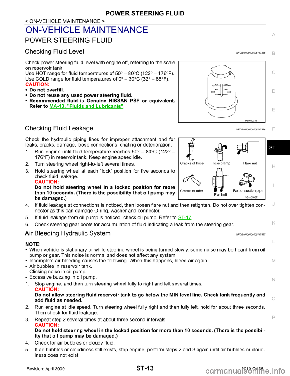
Check power steering fluid level with engine off, referring to the scale
on reservoir tank.
Use HOT range for fluid temperatures of 50 ° – 80 °C (122 ° – 176 °F).
Use COLD range for fluid temperatures of 0 ° – 30 °C (32° – 86°F).
CAUTION:
• Do not overfill.
• Do not reuse any used power steering fluid.
• Recommended fluid is Genuine NISSAN PSF or equivalent. Refer to MA-13, "
Fluids and Lubricants".
Checking Fluid LeakageINFOID:0000000005147866
Check the hydraulic piping lines for improper attachment and for
leaks, cracks, damage, loose connec tions, chafing or deterioration.
1. Run engine until fluid temperature reaches 50 ° – 80° C (122° –
176° F) in reservoir tank. Keep engine speed idle.
2. Turn steering wheel right-to-left several times.
3. Hold steering wheel at each “lock” position for five seconds to check fluid leakage.
CAUTION:
Do not hold steering wheel in a locked position for more
than 10 seconds. (There is the possibility that oil pump may
be damaged.)
4. If fluid leakage at connections is noticed, then loosen flare nut and then retighten. Do not over tighten con- nector as this can damage O-ring, washer and connector.
5. If fluid leakage from oil pump is noticed, check oil pump. Refer to ST-17
.
6. Check steering gear boots for accumulation of fluid indicating a leak from the steering gear.
Air Bleeding Hydraulic SystemINFOID:0000000005147867
NOTE:
• When vehicle is stationary or while steering wheel is being turned slowly, some noise may be heard from oil pump or gear. This noise is normal and does not affect any system.
• Incomplete air bleeding causes the fo llowing. When this happens, bleed air again.
- Air bubbles in reservoir tank.
- Clicking noise in oil pump.
- Excessive buzzing in oil pump.
1. Stop engine, and then turn steering wheel fully to right and left several times. CAUTION:
Do not allow steering fluid reservoir tank to go below the MIN level line. Check tank frequently and
add fluid as needed.
2. Run engine at idle speed. Turn steering wheel fully right and then fully left, hold for about three seconds.
Then check for fluid leakage.
3. Repeat step 2 several times at about three second intervals. CAUTION:
Do not hold steeri ng wheel in the locked position for more than 10 seconds. (There is the possibil-
ity that oil pump may be damaged.)
4. Check for air bubbles or cloudy fluid.
5. If air bubbles or cloudiness still exists, stop engine, perform steps 2 and 3 again until air bubbles or cloud-
iness does not exist.
LGIA0021E
SGIA0506E
Revision: April 20092010 QX56
Page 3655 of 4210
POWER STEERING OIL PUMPST-17
< ON-VEHICLE REPAIR >
C
DE
F
H I
J
K L
M A
B
ST
N
O P
POWER STEERING OIL PUMP
On-Vehicle Inspection and ServiceINFOID:0000000005147869
CHECKING RELIEF OIL PRESSURE
CAUTION:
Before starting work, confirm belt tension is proper.
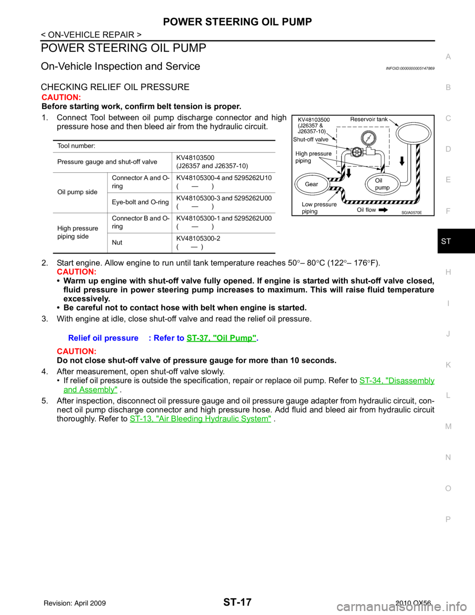
1. Connect Tool between oil pump discharge connector and high pressure hose and then bleed air from the hydraulic circuit.
2. Start engine. Allow engine to run until tank temperature reaches 50 °– 80° C (122° – 176°F).
CAUTION:
• Warm up engine with shut-off valve fully opened. If engine is started with shut-off valve closed,
fluid pressure in power steering pump increases to maximum. This will raise fluid temperature
excessively.
• Be careful not to contact hose with belt when engine is started.
3. With engine at idle, close shut-off valve and read the relief oil pressure.
CAUTION:
Do not close shut-off valve of pressure gauge for more than 10 seconds.
4. After measurement, open shut-off valve slowly. • If relief oil pressure is outside the specification, repair or replace oil pump. Refer to ST-34, "
Disassembly
and Assembly" .
5. After inspection, disconnect oil pressure gauge and oil pressure gauge adapter from hydraulic circuit, con-
nect oil pump discharge connector and high pressure hose. Add fluid and bleed air from hydraulic circuit
thoroughly. Refer to ST-13, "
Air Bleeding Hydraulic System" .
Tool number:
Pressure gauge and shut-off valve KV48103500
(J26357 and J26357-10)
Oil pump side Connector A and O-
ring
KV48105300-4 and 5295262U10
(—)
Eye-bolt and O-ring KV48105300-3 and 5295262U00
(—)
High pressure
piping side Connector B and O-
ring
KV48105300-1 and 5295262U00
(—)
Nut KV48105300-2
( — )
SGIA0570E
Relief oil pressure : Refer to
ST-37, "Oil Pump".
Revision: April 20092010 QX56
Page 3662 of 4210
ST-24
< REMOVAL AND INSTALLATION >
POWER STEERING GEAR AND LINKAGE
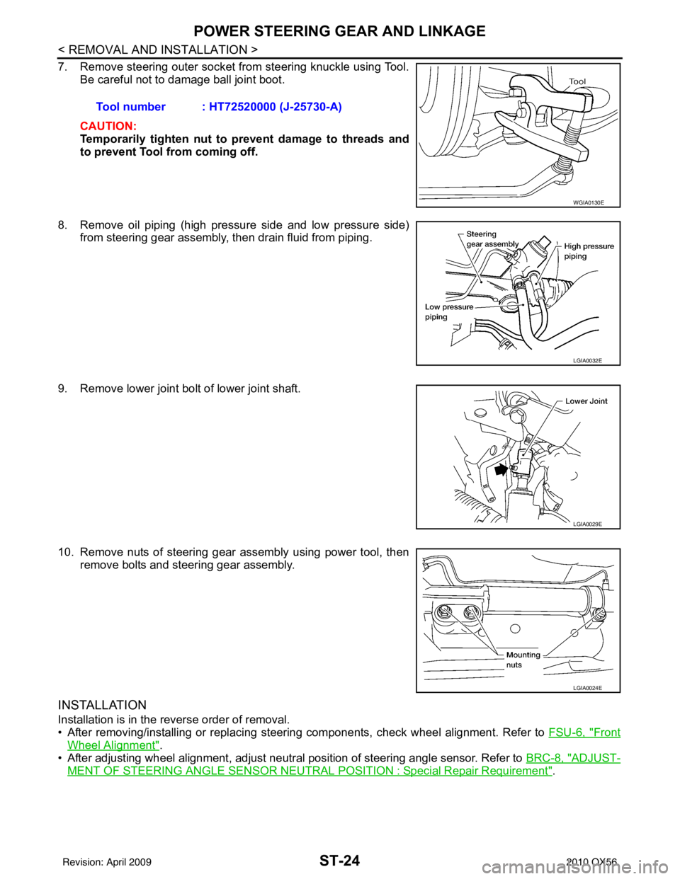
7. Remove steering outer socket from steering knuckle using Tool.Be careful not to damage ball joint boot.
CAUTION:
Temporarily tighten nut to prevent damage to threads and
to prevent Tool from coming off.
8. Remove oil piping (high pressure side and low pressure side) from steering gear assembly, then drain fluid from piping.
9. Remove lower joint bolt of lower joint shaft.
10. Remove nuts of steering gear assembly using power tool, then remove bolts and steering gear assembly.
INSTALLATION
Installation is in the reverse order of removal.
• After removing/installing or replacing steering components, check wheel alignment. Refer to FSU-6, "
Front
Wheel Alignment".
• After adjusting wheel alignment, adjust neutral position of steering angle sensor. Refer to BRC-8, "
ADJUST-
MENT OF STEERING ANGLE SENSOR NEUTRAL POSITION : Special Repair Requirement".
Tool number : HT72520000 (J-25730-A)
WGIA0130E
LGIA0032E
LGIA0029E
LGIA0024E
Revision: April 20092010 QX56