cooling INFINITI QX56 2010 Factory Workshop Manual
[x] Cancel search | Manufacturer: INFINITI, Model Year: 2010, Model line: QX56, Model: INFINITI QX56 2010Pages: 4210, PDF Size: 81.91 MB
Page 1920 of 4210
CYLINDER HEADEM-69
< ON-VEHICLE REPAIR >
C
DE
F
G H
I
J
K L
M A
EM
NP
O
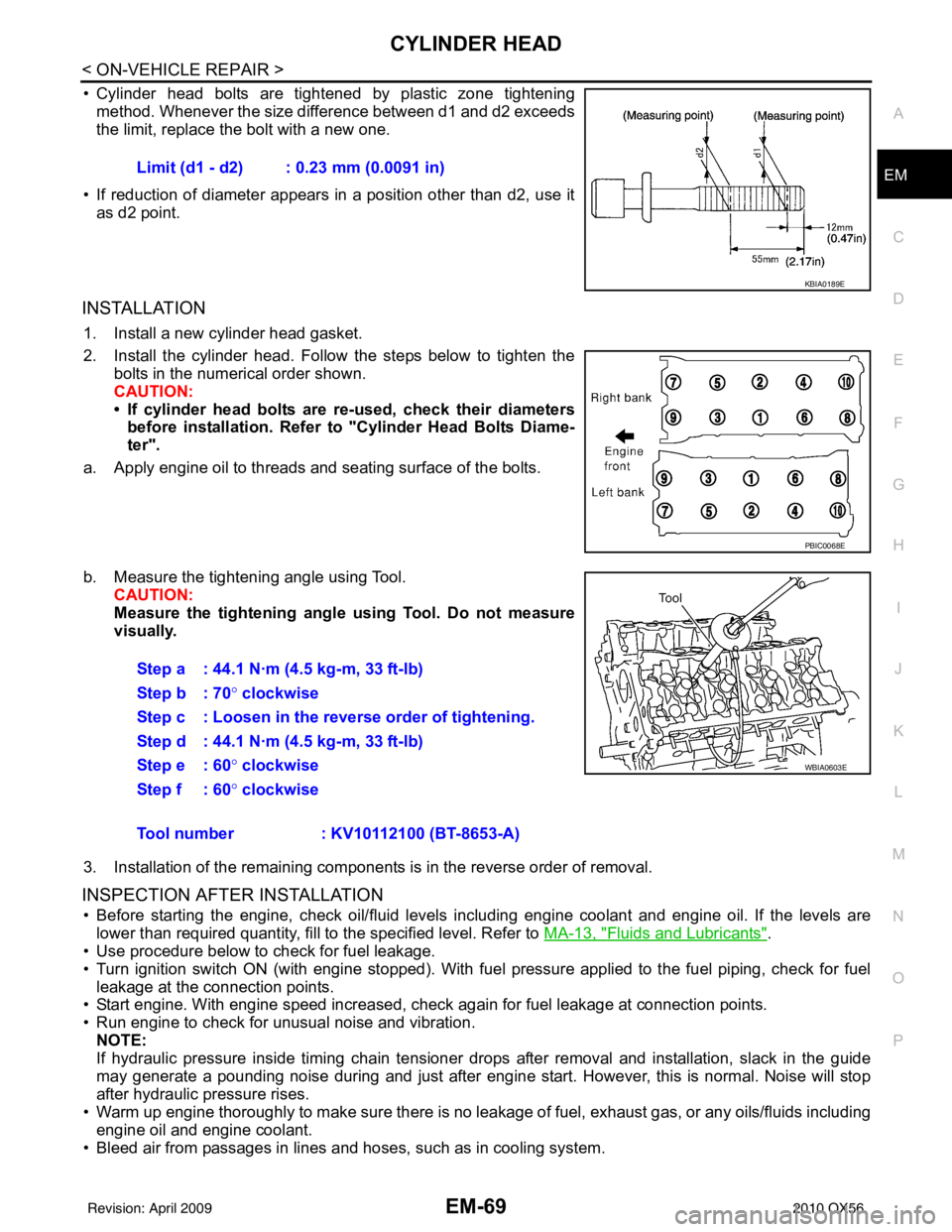
• Cylinder head bolts are tightened by plastic zone tightening
method. Whenever the size difference between d1 and d2 exceeds
the limit, replace the bolt with a new one.
• If reduction of diameter appears in a position other than d2, use it as d2 point.
INSTALLATION
1. Install a new cylinder head gasket.
2. Install the cylinder head. Follow the steps below to tighten the bolts in the numerical order shown.
CAUTION:
• If cylinder head bolts are re-used, check their diameters
before installation. Refer to "Cylinder Head Bolts Diame-
ter".
a. Apply engine oil to threads and seating surface of the bolts.
b. Measure the tightening angle using Tool. CAUTION:
Measure the tightening angl e using Tool. Do not measure
visually.
3. Installation of the remaining components is in the reverse order of removal.
INSPECTION AFTER INSTALLATION
• Before starting the engine, check oil/fluid levels including engine coolant and engine oil. If the levels are lower than required quantity, fill to the specified level. Refer to MA-13, "
Fluids and Lubricants".
• Use procedure below to check for fuel leakage.
• Turn ignition switch ON (with engine stopped). With fuel pressure applied to the fuel piping, check for fuel
leakage at the connection points.
• Start engine. With engine speed increased, check again for fuel leakage at connection points.
• Run engine to check for unusual noise and vibration.
NOTE:
If hydraulic pressure inside timing chain tensioner drops after removal and installation, slack in the guide
may generate a pounding noise during and just after engine start. However, this is normal. Noise will stop
after hydraulic pressure rises.
• Warm up engine thoroughly to make sure there is no leakage of fuel, exhaust gas, or any oils/fluids including
engine oil and engine coolant.
• Bleed air from passages in lines and hoses, such as in cooling system. Limit (d1 - d2) : 0.23 mm (0.0091 in)
KBIA0189E
PBIC0068E
Step a : 44.1 N·m (4.5 kg-m, 33 ft-lb)
Step b : 70°
clockwise
Step c : Loosen in the reverse order of tightening.
Step d : 44.1 N·m (4.5 kg-m, 33 ft-lb)
Step e : 60 ° clockwise
Step f : 60° clockwise
Tool number : KV10112100 (BT-8653-A)
WBIA0603E
Revision: April 20092010 QX56
Page 1921 of 4210
EM-70
< ON-VEHICLE REPAIR >
CYLINDER HEAD
• After cooling down the engine, again check oil/fluid levels including engine oil and engine coolant. Refill tospecified level if necessary.
• Summary of the inspection items:
*Transmission/transaxle/CVT fluid, power steering fluid, brake fluid, etc.
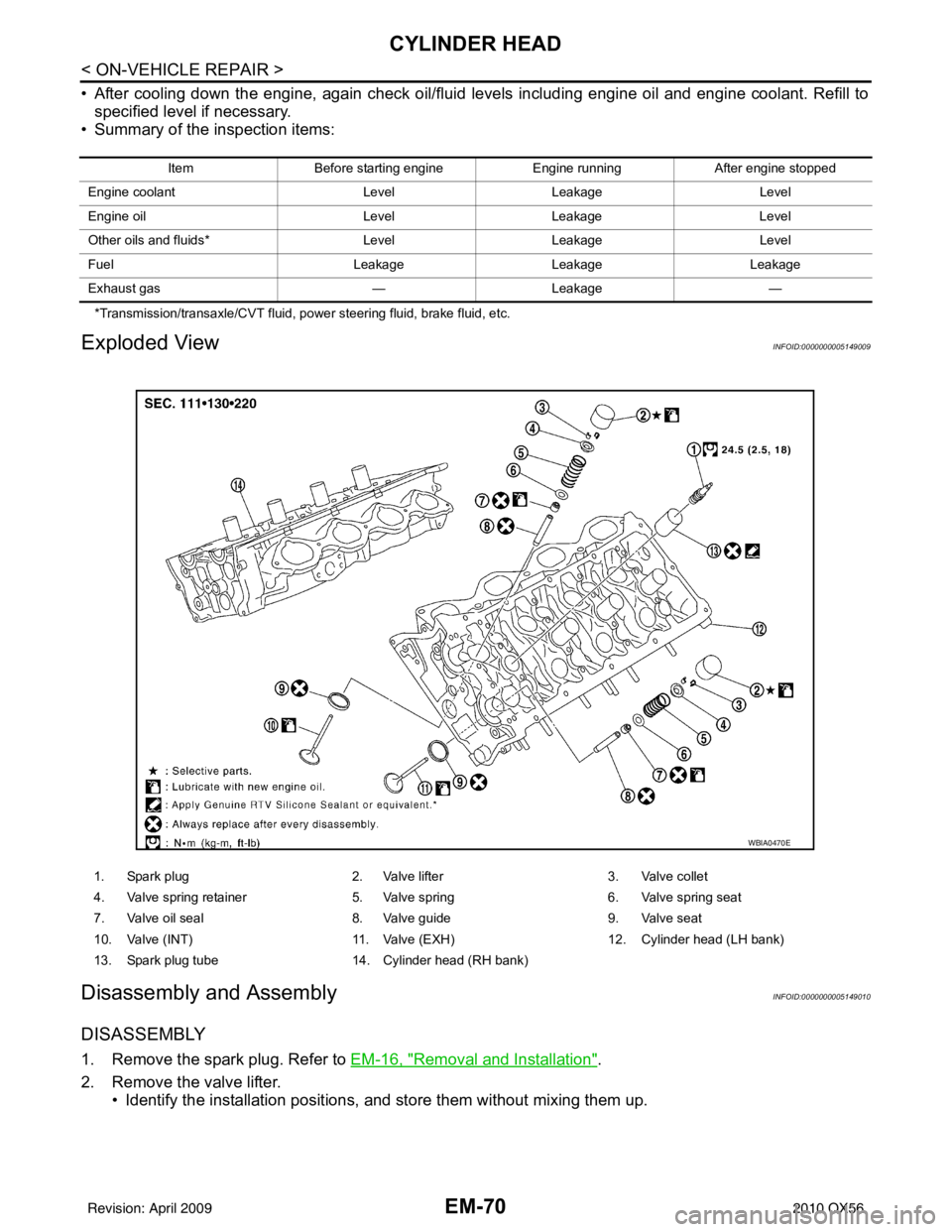
Exploded ViewINFOID:0000000005149009
Disassembly and AssemblyINFOID:0000000005149010
DISASSEMBLY
1. Remove the spark plug. Refer to EM-16, "Removal and Installation".
2. Remove the valve lifter. • Identify the installation positions, and store them without mixing them up.
Item Before starting engine Engine runningAfter engine stopped
Engine coolant LevelLeakage Level
Engine oil LevelLeakage Level
Other oils and fluids* LevelLeakage Level
Fuel LeakageLeakageLeakage
Exhaust gas —Leakage —
1. Spark plug 2. Valve lifter3. Valve collet
4. Valve spring retainer 5. Valve spring6. Valve spring seat
7. Valve oil seal 8. Valve guide9. Valve seat
10. Valve (INT) 11. Valve (EXH)12. Cylinder head (LH bank)
13. Spark plug tube 14. Cylinder head (RH bank)
WBIA0470E
Revision: April 20092010 QX56
Page 1932 of 4210
ENGINE ASSEMBLYEM-81
< REMOVAL AND INSTALLATION >
C
DE
F
G H
I
J
K L
M A
EM
NP
O
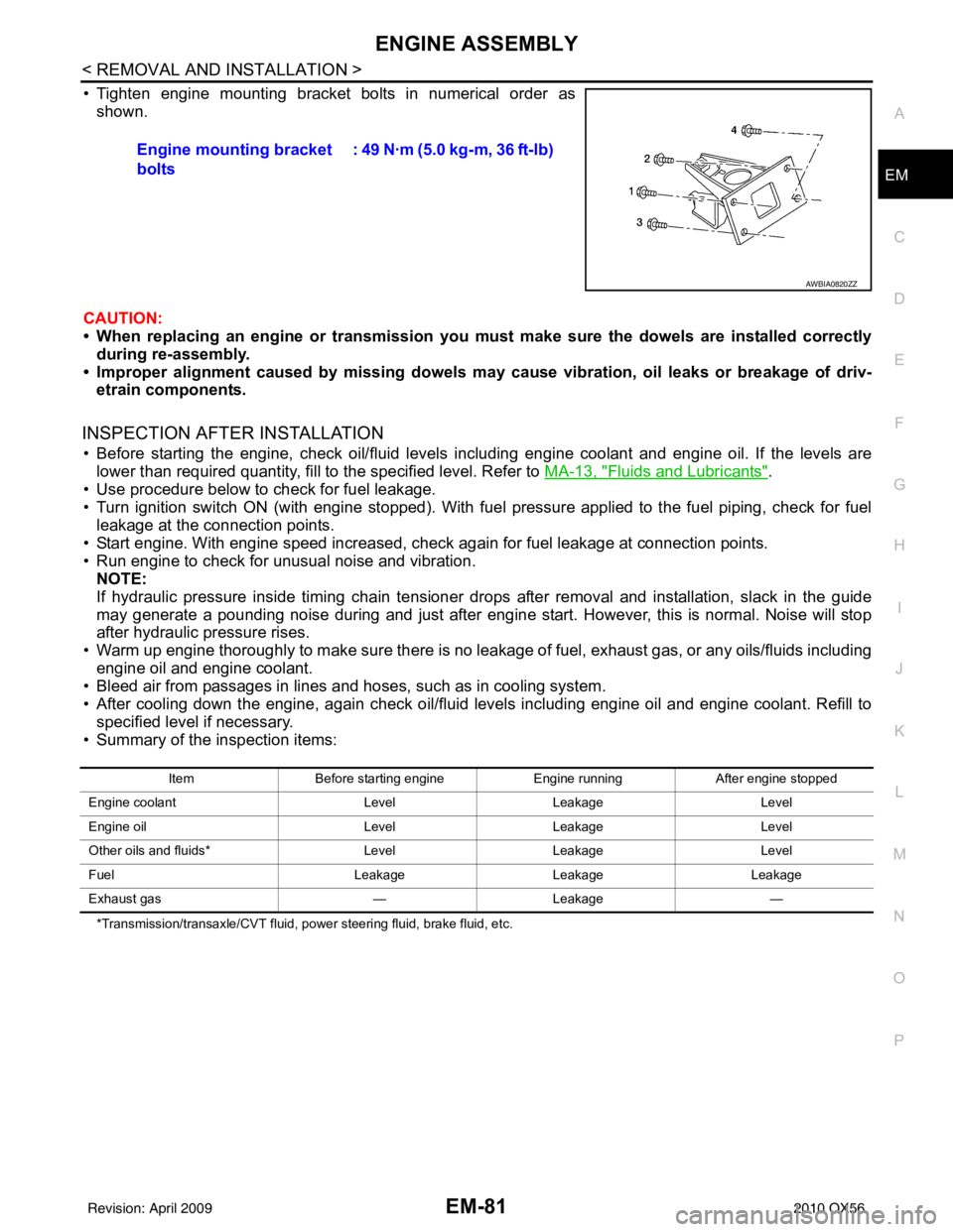
• Tighten engine mounting bracket bolts in numerical order as
shown.
CAUTION:
• When replacing an engine or tr ansmission you must make sure the dowels are installed correctly
during re-assembly.
• Improper alignment caused by missing dowels m ay cause vibration, oil leaks or breakage of driv-
etrain components.
INSPECTION AFTER INSTALLATION
• Before starting the engine, check oil/fluid levels including engine coolant and engine oil. If the levels are
lower than required quantity, fill to the specified level. Refer to MA-13, "
Fluids and Lubricants".
• Use procedure below to check for fuel leakage.
• Turn ignition switch ON (with engine stopped). With fuel pressure applied to the fuel piping, check for fuel leakage at the connection points.
• Start engine. With engine speed increased, check again for fuel leakage at connection points.
• Run engine to check for unusual noise and vibration. NOTE:
If hydraulic pressure inside timing chain tensioner drops after removal and installation, slack in the guide
may generate a pounding noise during and just after engine start. However, this is normal. Noise will stop
after hydraulic pressure rises.
• Warm up engine thoroughly to make sure there is no leakage of fuel, exhaust gas, or any oils/fluids including engine oil and engine coolant.
• Bleed air from passages in lines and hoses, such as in cooling system.
• After cooling down the engine, again check oil/fluid levels including engine oil and engine coolant. Refill to
specified level if necessary.
• Summary of the inspection items:
*Transmission/transaxle/CVT fluid, power steering fluid, brake fluid, etc.
Engine mounting bracket
bolts : 49 N·m (5.0 kg-m, 36 ft-lb)
AWBIA0820ZZ
Item
Before starting engine Engine runningAfter engine stopped
Engine coolant LevelLeakage Level
Engine oil LevelLeakage Level
Other oils and fluids* LevelLeakage Level
Fuel LeakageLeakage Leakage
Exhaust gas —Leakage —
Revision: April 20092010 QX56
Page 1998 of 4210
EXL-22
< FUNCTION DIAGNOSIS >
DIAGNOSIS SYSTEM (IPDM E/R)
DIAGNOSIS SYSTEM (IPDM E/R)
Diagnosis DescriptionINFOID:0000000005369886
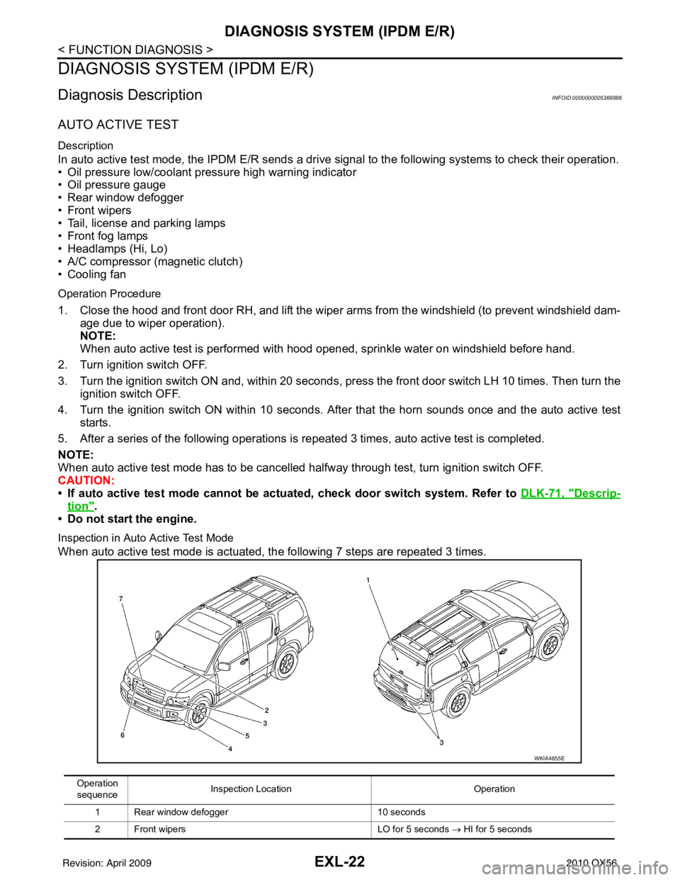
AUTO ACTIVE TEST
Description
In auto active test mode, the IPDM E/R sends a drive signal to the follo wing systems to check their operation.
• Oil pressure low/coolant pressure high warning indicator
• Oil pressure gauge
• Rear window defogger
• Front wipers
• Tail, license and parking lamps
• Front fog lamps
• Headlamps (Hi, Lo)
• A/C compressor (magnetic clutch)
• Cooling fan
Operation Procedure
1. Close the hood and front door RH, and lift the wiper a rms from the windshield (to prevent windshield dam-
age due to wiper operation).
NOTE:
When auto active test is performed with hood opened, sprinkle water on windshield before hand.
2. Turn ignition switch OFF.
3. Turn the ignition switch ON and, within 20 seconds, press the front door switch LH 10 times. Then turn the ignition switch OFF.
4. Turn the ignition switch ON within 10 seconds. Af ter that the horn sounds once and the auto active test
starts.
5. After a series of the following operations is repeated 3 times, auto active test is completed.
NOTE:
When auto active test mode has to be cancelled halfway through test, turn ignition switch OFF.
CAUTION:
• If auto active test mode cannot be actuated, check door switch system. Refer to DLK-71, "
Descrip-
tion".
• Do not start the engine.
Inspection in Auto Active Test Mode
When auto active test mode is actuated, the following 7 steps are repeated 3 times.
Operation
sequence Inspection Location
Operation
1 Rear window defogger 10 seconds
2 Front wipers LO for 5 seconds → HI for 5 seconds
WKIA4655E
Revision: April 20092010 QX56
Page 1999 of 4210
DIAGNOSIS SYSTEM (IPDM E/R)EXL-23
< FUNCTION DIAGNOSIS >
C
DE
F
G H
I
J
K
M A
B
EXL
N
O P
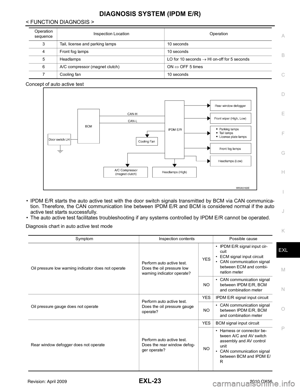
Concept of auto active test
• IPDM E/R starts the auto active test with the door
switch signals transmitted by BCM via CAN communica-
tion. Therefore, the CAN communication line between IPDM E/R and BCM is considered normal if the auto
active test starts successfully.
• The auto active test facilitates troubleshooting if any systems controlled by IPDM E/R cannot be operated.
Diagnosis chart in auto active test mode
3 Tail, license and parking lamps 10 seconds
4 Front fog lamps 10 seconds
5 Headlamps LO for 10 seconds → HI on-off for 5 seconds
6 A/C compressor (magnet clutch) ON ⇔ OFF 5 times
7 Cooling fan 10 seconds
Operation
sequence Inspection Location
Operation
WKIA5163E
SymptomInspection contentsPossible cause
Oil pressure low warning indicator does not operate Perform auto active test.
Does the oil pressure low
warning indicator operate?YES
• IPDM E/R signal input cir-
cuit
• ECM signal input circuit
• CAN communication signal
between ECM and combi-
nation meter
NO • CAN communication signal
between IPDM E/R, BCM
and combination meter
Oil pressure gauge does not operate Perform auto active test.
Does the oil pressure gauge
operate?YES IPDM E/R signal input circuit
NO • CAN communication signal
between IPDM E/R, BCM
and combination meter
Rear window defogger does not operate Perform auto active test.
Does the rear window defog-
ger operate?YES BCM signal input circuit
NO • Harness or connector be-
tween A/C and AV switch
assembly and AV control
unit
• CAN communication signal between BCM and IPDM E/
R
Revision: April 20092010 QX56
Page 2000 of 4210

EXL-24
< FUNCTION DIAGNOSIS >
DIAGNOSIS SYSTEM (IPDM E/R)
CONSULT - III Func tion (IPDM E/R)
INFOID:0000000005369887
APPLICATION ITEM
CONSULT-III performs the following functi ons via CAN communication with IPDM E/R.
SELF DIAGNOSTIC
Refer to PCS-32, "DTCIndex".
DATA MONITOR
Monitor item
Any of the following components do not operate
• Front wipers
•Tail lamps
• License plate lamps
• Parking lamps
•Front fog lamps
• Headlamps (Hi, Lo) Perform auto active test.
Does the applicable system
operate?YES BCM signal input system
NO • Lamp or front wiper motor
malfunction
• Lamp or front wiper motor ground circuit
• Harness or connector be-
tween IPDM E/R and appli-
cable system
• IPDM E/R (integrated relay
malfunction)
A/C compressor does not operate Perform auto active test.
Does the A/C compressor op-
erate?YES
• BCM signal input circuit
• CAN communication signal
between BCM and ECM
• CAN communication signal between ECM and IPDM E/
R
NO • Magnetic clutch malfunction
• Harness or connector be-
tween IPDM E/R and mag-
netic clutch
• IPDM E/R (integrated relay malfunction)
Cooling fan does not operate Perform auto active test.
Does the cooling fan operate?YES
• ECM signal input circuit
• CAN communication signal
between ECM and IPDM E/
R
NO • Cooling fan motor malfunc-
tion
• Harness or connector be- tween IPDM E/R and cool-
ing fan
• IPDM E/R (integrated relay malfunction)
Symptom
Inspection contentsPossible cause
Diagnosis mode Description
Self Diagnostic Result Displays the diagnosis results judged by IPDM E/R.
Data Monitor Displays the real-time input/output data from IPDM E/R input/output data.
Active Test IPDM E/R can provide a drive signal to electronic components to check their operations.
CAN Diag Support Monitor The results of transmit/receive diagnosis of CAN communication can be read.
Monitor Item
[Unit] MAIN SIG-
NALS Description
MOTOR FAN REQ
[1/2/3/4] ×
Displays the status of the cooling fan speed request signal received from ECM via
CAN communication.
A/C COMP REQ
[OFF/ON] ×Displays the status of the A/C request signal received from AV control unit via
CAN communication.
Revision: April 20092010 QX56
Page 2001 of 4210
![INFINITI QX56 2010 Factory Workshop Manual DIAGNOSIS SYSTEM (IPDM E/R)EXL-25
< FUNCTION DIAGNOSIS >
C
DE
F
G H
I
J
K
M A
B
EXL
N
O P
ACTIVE TEST
Te s t i t e m
TAIL&CLR REQ
[OFF/ON] ×Displays the status of the position light request signal r INFINITI QX56 2010 Factory Workshop Manual DIAGNOSIS SYSTEM (IPDM E/R)EXL-25
< FUNCTION DIAGNOSIS >
C
DE
F
G H
I
J
K
M A
B
EXL
N
O P
ACTIVE TEST
Te s t i t e m
TAIL&CLR REQ
[OFF/ON] ×Displays the status of the position light request signal r](/img/42/57032/w960_57032-2000.png)
DIAGNOSIS SYSTEM (IPDM E/R)EXL-25
< FUNCTION DIAGNOSIS >
C
DE
F
G H
I
J
K
M A
B
EXL
N
O P
ACTIVE TEST
Te s t i t e m
TAIL&CLR REQ
[OFF/ON] ×Displays the status of the position light request signal received from BCM via CAN
communication.
HL LO REQ
[OFF/ON] ×
Displays the status of the low beam request signal received from BCM via CAN
communication.
HL HI REQ
[OFF/ON] ×Displays the status of the high beam request signal received from BCM via CAN
communication.
FR FOG REQ
[OFF/ON] ×Displays the status of the front fog lamp request signal received from BCM via
CAN communication.
FR WIP REQ
[STOP/1LOW/LOW/HI] ×
Displays the status of the front wiper request signal received from BCM via CAN
communication.
WIP AUTO STOP
[STOP P/ACT P] ×
Displays the status of the front wiper auto stop signal judged by IPDM E/R.
WIP PROT
[OFF/Block] ×
Displays the status of the front wiper fail-safe operation judged by IPDM E/R.
ST RLY REQ
[OFF/ON] Displays the status of the starter request signal received from ECM via CAN com-
munication.
IGN RLY
[OFF/ON] ×
Displays the status of the ignition relay judged by IPDM E/R.
RR DEF REQ
[OFF/ON] ×Displays the status of the rear defogger request signal received from AV control
unit via CAN communication.
OIL P SW
[OPEN/CLOSE] Displays the status of the oil pressure switch judged by IPDM E/R.
DTRL REQ
[OFF] Displays the status of the daytime light request signal received from BCM via CAN
communication.
HOOD SW
[OPEN/CLOSE] Displays the status of the hood switch judged by IPDM E/R.
THFT HRN REQ
[OFF/ON] Displays the status of the theft warning horn request signal received from BCM
via CAN communication.
HORN CHIRP
[OFF/ON] Displays the status of the horn reminder signal received from BCM via CAN com-
munication.
Monitor Item
[Unit] MAIN SIG-
NALS Description
Test item
Operation Description
REAR DEFOGGER OFF
OFF
ON Operates rear window defogger relay.
FRONT WIPER OFF
OFF
LO Operates the front wiper relay.
HI Operates the front wiper relay and front wiper high relay.
MOTOR FAN 1O
FF
2O FF
3 Operates the cooling fan relay.
4 Operates the cooling fan relay.
Revision: April 20092010 QX56
Page 2102 of 4210

EXL-126
< ECU DIAGNOSIS >
IPDM E/R (INTELLIGENT POWER DISTRIBUTION MODULE ENGINE ROOM)
Te r m i n a lWire
color Signal name Signal
input/
output Measuring condition
Reference value(Approx.)
Igni-
tion
switch Operation or condition
1 B/Y Battery power supply Input OFF —Battery voltage
2 R Battery power supply Input OFF —Battery voltage
3 BR ECM relay Output —Ignition switch ON or START
Battery voltage
Ignition switch OFF or ACC 0V
4 W/L ECM relay Output —Ignition switch ON or START
Battery voltage
Ignition switch OFF or ACC 0V
6L Throttle control motor
relay Output —Ignition switch ON or START
Battery voltage
Ignition switch OFF or ACC 0V
7 W/B ECM relay control Input — Ignition switch ON or START
0V
Ignition switch OFF or ACC Battery voltage
8 R/B Fuse 54 Output —Ignition switch ON or START
Battery voltage
Ignition switch OFF or ACC 0V
10 G Fuse 45
(Canada only) Output ONDaytime light system active
0V
Daytime light system inactive Battery voltage
11 Y/B A/C compressor Output ON or
START A/C switch ON or defrost A/C
switch
Battery voltage
A/C switch OFF or defrost A/C
switch 0V
12 L/W Ignition switch sup-
plied power Input —OFF or ACC
0V
ON or START Battery voltage
13 B/Y Fuel pump relay Output — Ignition switch ON or START
Battery voltage
Ignition switch OFF or ACC 0V
14 Y/R Fuse 49 Output —Ignition switch ON or START
Battery voltage
Ignition switch OFF or ACC 0V
15 LG/B Fuse 50 Output —Ignition switch ON or START
Battery voltage
Ignition switch OFF or ACC 0V
16 G Fuse 51 Output —Ignition switch ON or START
Battery voltage
Ignition switch OFF or ACC 0V
17 W Fuse 55 Output —Ignition switch ON or START
Battery voltage
Ignition switch OFF or ACC 0V
19 W/R Starter motor Output START—Battery voltage
21 BR Ignition switch sup-
plied power
Input —OFF or ACC
0V
START Battery voltage
22 G Battery power supply Output OFF —Battery voltage
23 GR/W Door mirror defogger
output signal Output —When rear defogger switch is
ON
Battery voltage
When raker defogger switch is
OFF 0V
24 L Cooling fan relay Output — Conditions correct for cooling
fan operation
Battery voltage
Conditions not correct for
cooling fan operation 0V
Revision: April 20092010 QX56
Page 2110 of 4210

EXL-134
< ECU DIAGNOSIS >
IPDM E/R (INTELLIGENT POWER DISTRIBUTION MODULE ENGINE ROOM)
If No CAN Communication Is Available With BCM
IGNITION RELAY MALFUNCTION DETECTION FUNCTION
• IPDM E/R monitors the voltage at the contact circuit and excitation coil circuit of the ignition relay inside it.
• IPDM E/R judges the ignition relay error if the voltage differs between the contact circuit and the excitation
coil circuit.
• If the ignition relay cannot turn OFF due to contact seizure, it activates the tail lamp relay for 10 minutes to alert the user to the ignition relay malfunction when the ignition switch is turned OFF.
NOTE:
The tail lamp turns OFF when the ignition switch is turned ON.
FRONT WIPER CONTROL
IPDM E/R detects front wiper stop posit ion by a front wiper auto stop signal.
When a front wiper auto stop signal is in the conditions listed below, IPDM E/R stops power supply to wiper
after repeating a front wiper 10 second activation and 20 second stop five times.
NOTE:
This operation status can be confirmed on the IPDM E/R “DATA MONITOR” that displays “Block” for the item
“WIP PROT” while the wiper is stopped.
STARTER MOTOR PROTECTION FUNCTION
IPDM E/R turns OFF the starter control relay to protect the starter motor when the starter control relay remains
active for 90 seconds.
Control part Fail-safe in operation
Cooling fan • Turns ON the cooling fan relay when the ignition switch is turned ON
• Turns OFF the cooling fan relay when the ignition switch is turned OFF
Control part
Fail-safe in operation
Headlamp • Turns ON the headlamp low relay when the ignition switch is turned ON
• Turns OFF the headlamp low relay when the ignition switch is turned OFF
• Headlamp high LH/RH relays OFF
•Parking lamps
• License plate lamps
• Tail lamps • Turns ON the tail lamp relay when the ignition switch is turned ON
• Turns OFF the tail lamp relay when the ignition switch is turned OFF
Front wiper • The status just before activation of fail-safe control is maintained until the ignition
switch is turned OFF while the front wiper is operating at LO or HI speed.
• The wiper is operated at LO speed until the ignition switch is turned OFF if the fail- safe control is activated while the front wipe r is set in the INT mode and the front wiper
motor is operating.
Rear window defogger Rear window defogger relay OFF
A/C compressor A/C relay OFF
Front fog lamps Front fog lamp relay OFF
Ignition switch Ignition relayTail lamp relay
ON ON —
OFF OFF —
Ignition switchFront wiper switch Auto stop signal
ON OFF
Front wiper stop position signal cannot be
input 10 seconds.
ON The signal does not change for 10 seconds.
Revision: April 20092010 QX56
Page 2256 of 4210
TOW TRUCK TOWINGGI-33
< PRECAUTION >
C
DE
F
G H
I
J
K L
M B
GI
N
O P
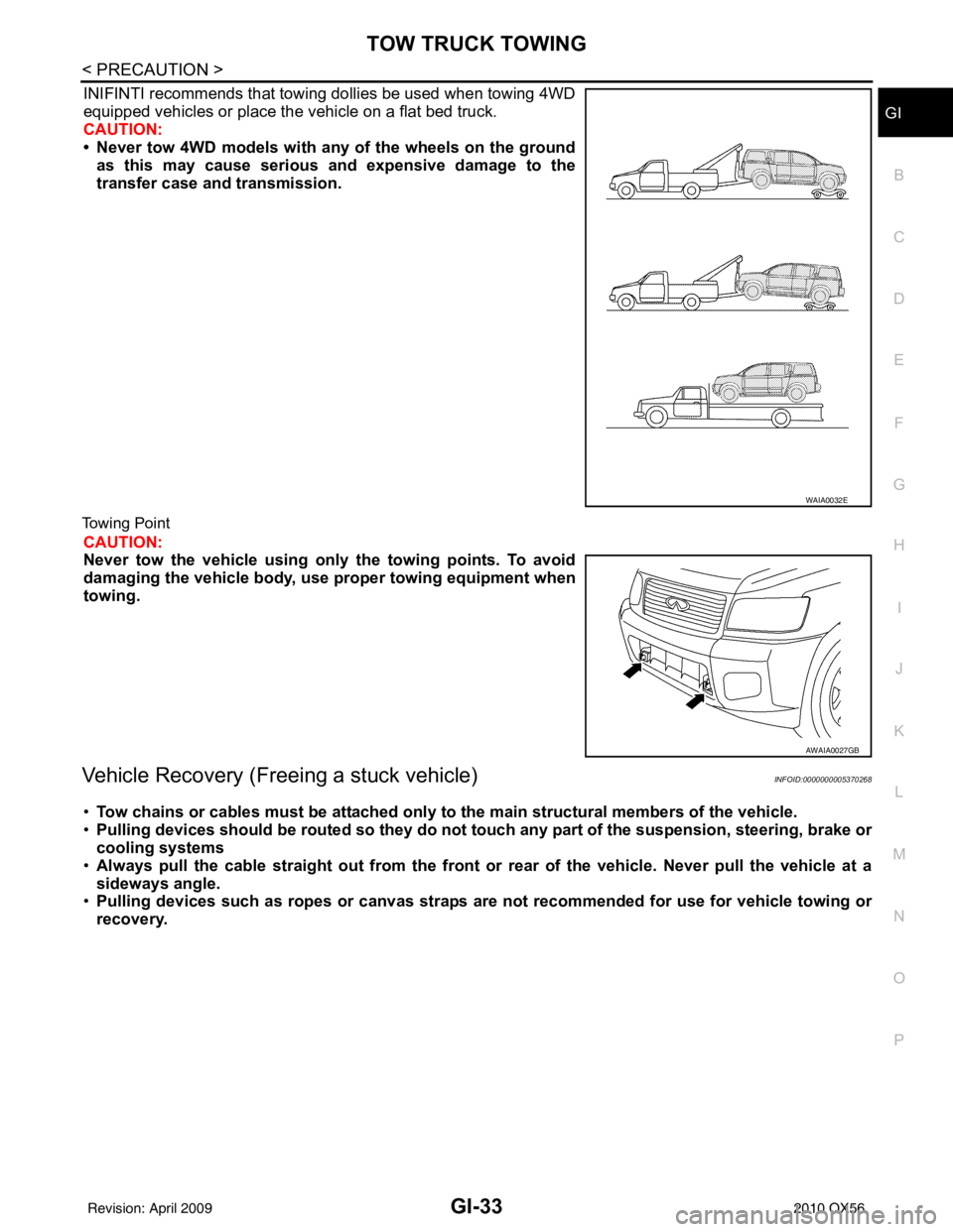
INIFINTI recommends that towing dollies be used when towing 4WD
equipped vehicles or place the vehicle on a flat bed truck.
CAUTION:
• Never tow 4WD models with any of the wheels on the ground as this may cause serious and expensive damage to the
transfer case and transmission.
Towing Point
CAUTION:
Never tow the vehicle using only the towing points. To avoid
damaging the vehicle body, use proper towing equipment when
towing.
Vehicle Recovery (Freeing a stuck vehicle)INFOID:0000000005370268
•Tow chains or cables must be attached only to the main structural members of the vehicle.
• Pulling devices should be routed so they do not touch any part of the suspension, steering, brake or
cooling systems
• Always pull the cable straight out from the front or rear of the vehicle. Never pull the vehicle at a
sideways angle.
• Pulling devices such as ropes or canvas straps are not recommended for use for vehicle towing or
recovery.
WAIA0032E
AWAIA0027GB
Revision: April 20092010 QX56