clock INFINITI QX56 2010 Factory Manual Online
[x] Cancel search | Manufacturer: INFINITI, Model Year: 2010, Model line: QX56, Model: INFINITI QX56 2010Pages: 4210, PDF Size: 81.91 MB
Page 3172 of 4210
RF-44
< SYMPTOM DIAGNOSIS >
SQUEAK AND RATTLE TROUBLE DIAGNOSES
SQUEAK AND RATTLE TROUBLE DIAGNOSES
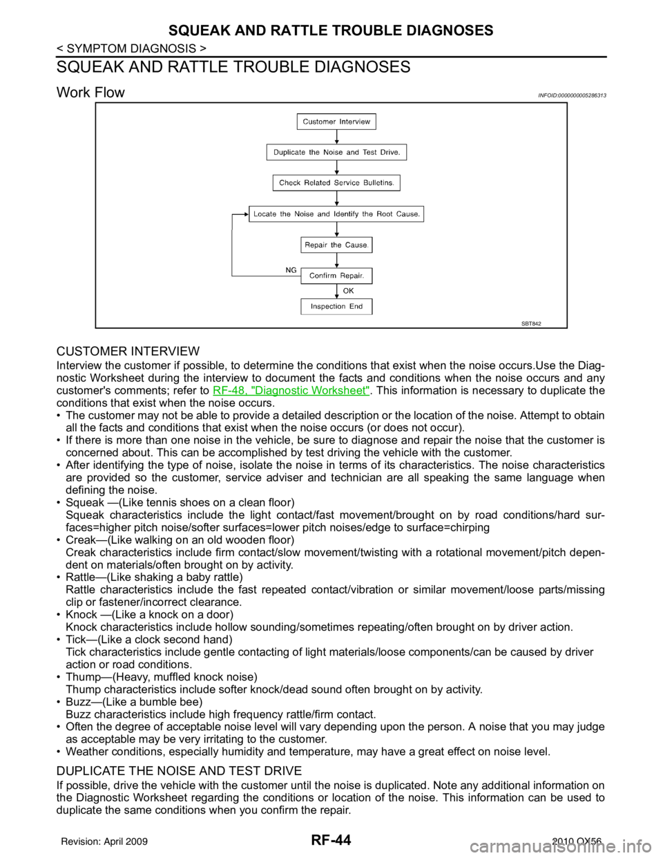
Work FlowINFOID:0000000005286313
CUSTOMER INTERVIEW
Interview the customer if possible, to determine the conditions that exist when the noise occurs.Use the Diag-
nostic Worksheet during the interview to document the facts and conditions when the noise occurs and any
customer's comments; refer to RF-48, "
Diagnostic Worksheet". This information is necessary to duplicate the
conditions that exist when the noise occurs.
• The customer may not be able to provide a detailed description or the location of the noise. Attempt to obtain all the facts and conditions that exist w hen the noise occurs (or does not occur).
• If there is more than one noise in the vehicle, be sure to diagnose and repair the noise that the customer is
concerned about. This can be accomplished by test driving the vehicle with the customer.
• After identifying the type of noise, isolate the noise in terms of its characteristics. The noise characteristics
are provided so the customer, service adviser and technician are all speaking the same language when
defining the noise.
• Squeak —(Like tennis shoes on a clean floor)
Squeak characteristics include the light contact/fa st movement/brought on by road conditions/hard sur-
faces=higher pitch noise/softer surfaces=l ower pitch noises/edge to surface=chirping
• Creak—(Like walking on an old wooden floor)
Creak characteristics include firm contact/slow mo vement/twisting with a rotational movement/pitch depen-
dent on materials/often brought on by activity.
• Rattle—(Like shaking a baby rattle)
Rattle characteristics include the fast repeated contac t/vibration or similar movement/loose parts/missing
clip or fastener/incorrect clearance.
• Knock —(Like a knock on a door)
Knock characteristics include hollow sounding/someti mes repeating/often brought on by driver action.
• Tick—(Like a clock second hand) Tick characteristics include gentle contacting of light materials/loose components/can be caused by driver
action or road conditions.
• Thump—(Heavy, muffled knock noise) Thump characteristics include softer k nock/dead sound often brought on by activity.
• Buzz—(Like a bumble bee)
Buzz characteristics include hi gh frequency rattle/firm contact.
• Often the degree of acceptable noise level will vary depending upon the person. A noise that you may judge as acceptable may be very irritating to the customer.
• Weather conditions, especially humidity and temperat ure, may have a great effect on noise level.
DUPLICATE THE NOISE AND TEST DRIVE
If possible, drive the vehicle with the customer until the noise is duplicated. Note any additional information on
the Diagnostic Worksheet regarding the conditions or lo cation of the noise. This information can be used to
duplicate the same conditions when you confirm the repair.
SBT842
Revision: April 20092010 QX56
Page 3292 of 4210
SE-20
< COMPONENT DIAGNOSIS >
THIRD SEAT
Do all terminals have ground?
YES >> Inspection End.
NO >> Check harness for ground.
Third Row Power Folding Seat SwitchINFOID:0000000005147388
1.CHECK THIRD ROW POWER FOLDING SEAT SWITCH OPERATION
1. Turn ignition switch OFF.
2. Disconnect third row power folding seat switch.
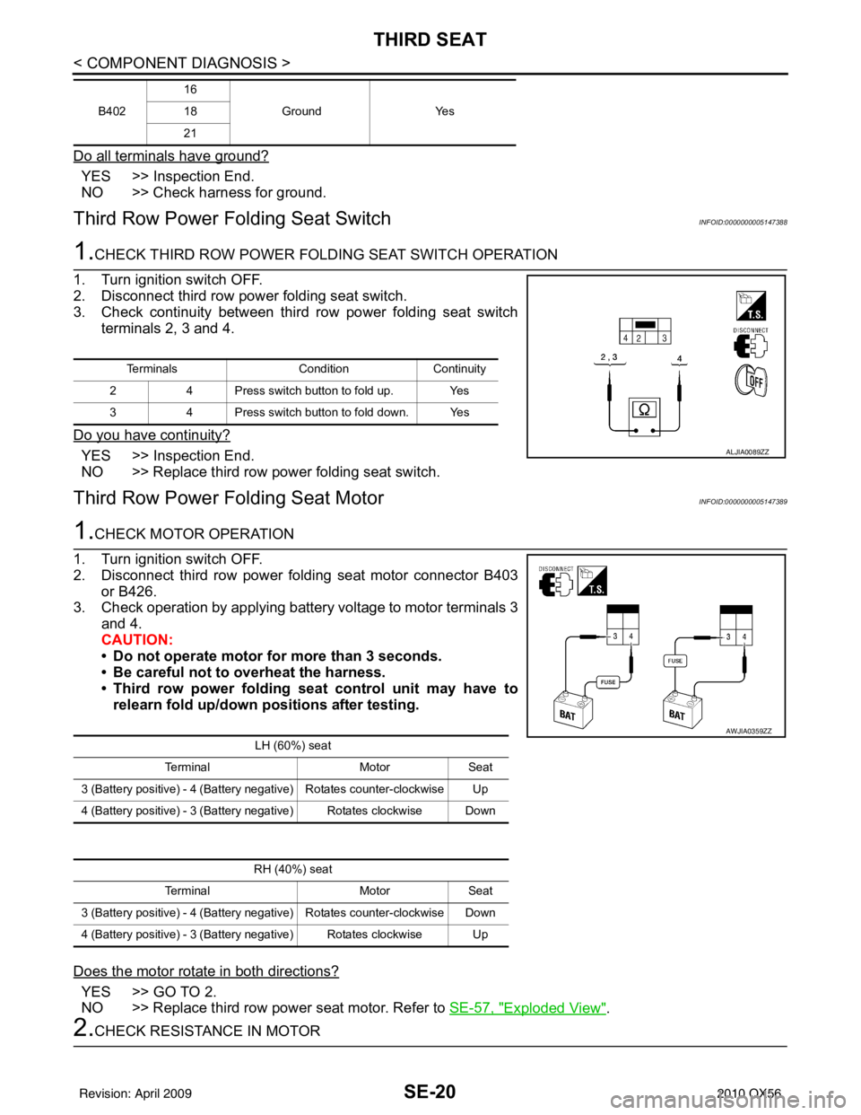
3. Check continuity between third row power folding seat switch terminals 2, 3 and 4.
Do you have continuity?
YES >> Inspection End.
NO >> Replace third row power folding seat switch.
Third Row Power Folding Seat MotorINFOID:0000000005147389
1.CHECK MOTOR OPERATION
1. Turn ignition switch OFF.
2. Disconnect third row power folding seat motor connector B403 or B426.
3. Check operation by applying battery voltage to motor terminals 3
and 4.
CAUTION:
• Do not operate motor for more than 3 seconds.
• Be careful not to overheat the harness.
• Third row power folding seat control unit may have to
relearn fold up/down positions after testing.
Does the motor rotate in both directions?
YES >> GO TO 2.
NO >> Replace third row power seat motor. Refer to SE-57, "
Exploded View".
2.CHECK RESISTANCE IN MOTOR
B40216
Ground Yes
18
21
Terminals Condition Continuity
2 4 Press switch button to fold up. Yes
3 4 Press switch button to fold down. Yes
ALJIA0089ZZ
LH (60%) seat
Terminal MotorSeat
3 (Battery positive) - 4 (Battery negative) Rotates counter-clockwise Up
4 (Battery positive) - 3 (Battery negative) Rotates clockwise Down
AWJIA0359ZZ
RH (40%) seat
Terminal MotorSeat
3 (Battery positive) - 4 (Battery negative) Rotates counter-clockwise Down
4 (Battery positive) - 3 (Battery negative) Rotates clockwise Up
Revision: April 20092010 QX56
Page 3311 of 4210
SQUEAK AND RATTLE TROUBLE DIAGNOSESSE-39
< SYMPTOM DIAGNOSIS >
C
DE
F
G H
I
K L
M A
B
SE
N
O P
SQUEAK AND RATTLE TROUBLE DIAGNOSES
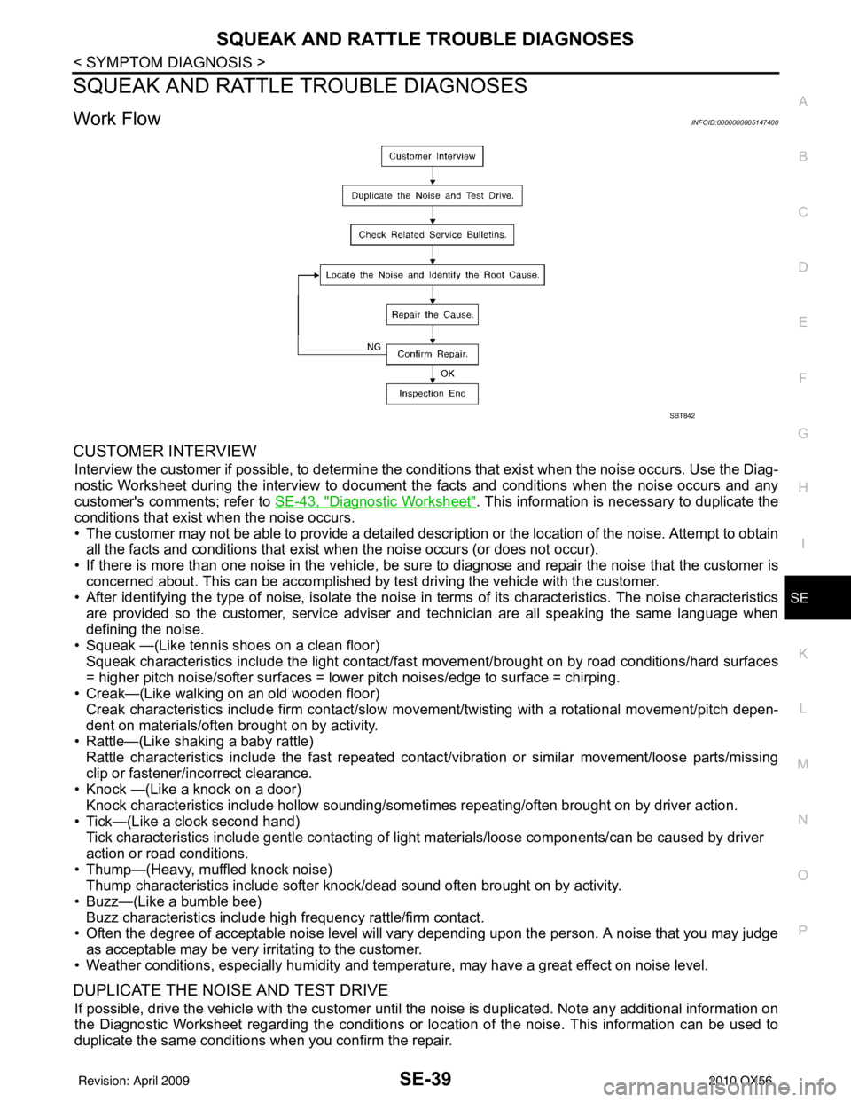
Work FlowINFOID:0000000005147400
CUSTOMER INTERVIEW
Interview the customer if possible, to determine the conditions that exist when the noise occurs. Use the Diag-
nostic Worksheet during the interv iew to document the facts and conditions when the noise occurs and any
customer's comments; refer to SE-43, "
Diagnostic Worksheet". This information is necessary to duplicate the
conditions that exist when the noise occurs.
• The customer may not be able to provide a detailed descr iption or the location of the noise. Attempt to obtain
all the facts and conditions that exist when the noise occurs (or does not occur).
• If there is more than one noise in the vehicle, be sure to diagnose and repair the noise that the customer is
concerned about. This can be accomplished by test driving the vehicle with the customer.
• After identifying the type of noise, isolate the noise in terms of its characteristics. The noise characteristics
are provided so the customer, service adviser and technician are all speaking the same language when
defining the noise.
• Squeak —(Like tennis shoes on a clean floor)
Squeak characteristics include the light contact/fast movement/brought on by road conditions/hard surfaces
= higher pitch noise/softer surfaces = lower pitch noises/edge to surface = chirping.
• Creak—(Like walking on an old wooden floor)
Creak characteristics include firm contact/slow mo vement/twisting with a rotational movement/pitch depen-
dent on materials/often brought on by activity.
• Rattle—(Like shaking a baby rattle)
Rattle characteristics include the fast repeated contac t/vibration or similar movement/loose parts/missing
clip or fastener/incorrect clearance.
• Knock —(Like a knock on a door)
Knock characteristics include hollow sounding/someti mes repeating/often brought on by driver action.
• Tick—(Like a clock second hand) Tick characteristics include gentle contacting of li ght materials/loose components/can be caused by driver
action or road conditions.
• Thump—(Heavy, muffled knock noise) Thump characteristics include softer k nock/dead sound often brought on by activity.
• Buzz—(Like a bumble bee)
Buzz characteristics include high frequency rattle/firm contact.
• Often the degree of acceptable noise level will vary depending upon the person. A noise that you may judge as acceptable may be very irritating to the customer.
• Weather conditions, especially humidity and temperature, may have a great effect on noise level.
DUPLICATE THE NOISE AND TEST DRIVE
If possible, drive the vehicle with the customer until the noise is duplicated. Note any additional information on
the Diagnostic Worksheet regarding the conditions or lo cation of the noise. This information can be used to
duplicate the same conditions when you confirm the repair.
SBT842
Revision: April 20092010 QX56
Page 3416 of 4210
![INFINITI QX56 2010 Factory Manual Online BCM (BODY CONTROL MODULE)SEC-65
< ECU DIAGNOSIS > [WITH INTELLIGENT KEY SYSTEM]
C
D
E
F
G H
I
J
L
M A
B
SEC
N
O P
19 V/W Remote keyless entry
receiver (power sup-
ply) Output OFF Ignition switch OFF
INFINITI QX56 2010 Factory Manual Online BCM (BODY CONTROL MODULE)SEC-65
< ECU DIAGNOSIS > [WITH INTELLIGENT KEY SYSTEM]
C
D
E
F
G H
I
J
L
M A
B
SEC
N
O P
19 V/W Remote keyless entry
receiver (power sup-
ply) Output OFF Ignition switch OFF](/img/42/57032/w960_57032-3415.png)
BCM (BODY CONTROL MODULE)SEC-65
< ECU DIAGNOSIS > [WITH INTELLIGENT KEY SYSTEM]
C
D
E
F
G H
I
J
L
M A
B
SEC
N
O P
19 V/W Remote keyless entry
receiver (power sup-
ply) Output OFF Ignition switch OFF
20 G/W Remote keyless entry
receiver (signal) Input OFFStand-by (keyfob buttons re-
leased)
When remote keyless entry
receiver receives signal from
keyfob (keyfob buttons
pressed)
21 G NATS antenna amp. Input OFF
→
ON Ignition switch (OFF → ON) Just after turning ignition switch
ON: Pointer of tester should
move for approx. 1 second, then return to battery voltage.
22 W/V BUS — —Ignition switch ON or power
window timer operates
23 G/O Security indicator
lamp Output OFF
Goes OFF
→ illuminates (Ev-
ery 2.4 seconds) Battery voltage
→ 0V
25 BR NATS antenna amp. Input OFF
→
ON Ignition switch (OFF → ON) Just after turning ignition switch
ON: Pointer of tester should
move for approx. 1 second, then return to battery voltage.
26 Y/L Rear wiper auto stop
switch 2 Input ONRise up position (rear wiper
arm on stopper)
0V
A Position (full clockwise stop
position) 0V
Forward sweep (counterclock-
wise direction) Fluctuating
B Position (full counterclock-
wise stop position) Battery voltage
Reverse sweep (clockwise di-
rection) Fluctuating
27 W/R Compressor ON sig-
nal Input ONA/C switch OFF
5V
A/C switch ON 0V
Te r m i n a l
Wire
color Signal name Signal
input/
output Measuring condition
Reference value or waveform
(Approx.)
Ignition
switch Operation or condition
LIIA1893E
LIIA1894E
LIIA1895E
PIIA2344E
Revision: April 20092010 QX56
Page 3418 of 4210
![INFINITI QX56 2010 Factory Manual Online BCM (BODY CONTROL MODULE)SEC-67
< ECU DIAGNOSIS > [WITH INTELLIGENT KEY SYSTEM]
C
D
E
F
G H
I
J
L
M A
B
SEC
N
O P
44 O Rear wiper auto stop
switch 1 Input ONRise up position (rear wiper
arm on stopp INFINITI QX56 2010 Factory Manual Online BCM (BODY CONTROL MODULE)SEC-67
< ECU DIAGNOSIS > [WITH INTELLIGENT KEY SYSTEM]
C
D
E
F
G H
I
J
L
M A
B
SEC
N
O P
44 O Rear wiper auto stop
switch 1 Input ONRise up position (rear wiper
arm on stopp](/img/42/57032/w960_57032-3417.png)
BCM (BODY CONTROL MODULE)SEC-67
< ECU DIAGNOSIS > [WITH INTELLIGENT KEY SYSTEM]
C
D
E
F
G H
I
J
L
M A
B
SEC
N
O P
44 O Rear wiper auto stop
switch 1 Input ONRise up position (rear wiper
arm on stopper)
0V
A Position (full clockwise stop
position) Battery voltage
Forward sweep (counterclock-
wise direction) Fluctuating
B Position (full counterclock-
wise stop position) 0V
Reverse sweep (clockwise di-
rection) Fluctuating
47 SB Front door switch LH Input OFF ON (open)
0V
OFF (closed) Battery voltage
48 R/Y Rear door switch LH Input OFF ON (open)
0V
OFF (closed) Battery voltage
49 R Cargo lamp Output OFFAny door open (ON)
0V
All doors closed (OFF) Battery voltage
51 G/Y Trailer turn signal
(right) Output ON Turn right ON
52 G/B Trailer turn signal (left) Output ON Turn left ON
53 L/W Glass hatch lock actu-
ator
Output OFFGlass hatch switch released
0V
Glass hatch switch pressed Battery voltage
54 Y Rear wiper output cir-
cuit 2 Input ONRise up position (rear wiper
arm on stopper)
0V
A Position (full clockwise stop
position) 0V
Forward sweep (counterclock-
wise direction) 0V
B Position (full counterclock-
wise stop position) Battery voltage
Reverse sweep (clockwise di-
rection) Battery voltage
55 SB Rear wiper output cir-
cuit 1 Output ONOFF
0V
ON Battery voltage
56 R/G Battery saver output Output OFF
30 minutes after ignition
switch is turned OFF 0V
ON — Battery voltage
57 Y/R Battery power supply Input OFF —Battery voltage
Te r m i n a l
Wire
color Signal name Signal
input/
output Measuring condition
Reference value or waveform
(Approx.)
Ignition
switch Operation or condition
SKIA3009J
SKIA3009J
Revision: April 20092010 QX56
Page 3531 of 4210
SR-8
< ON-VEHICLE REPAIR >
SPIRAL CABLE
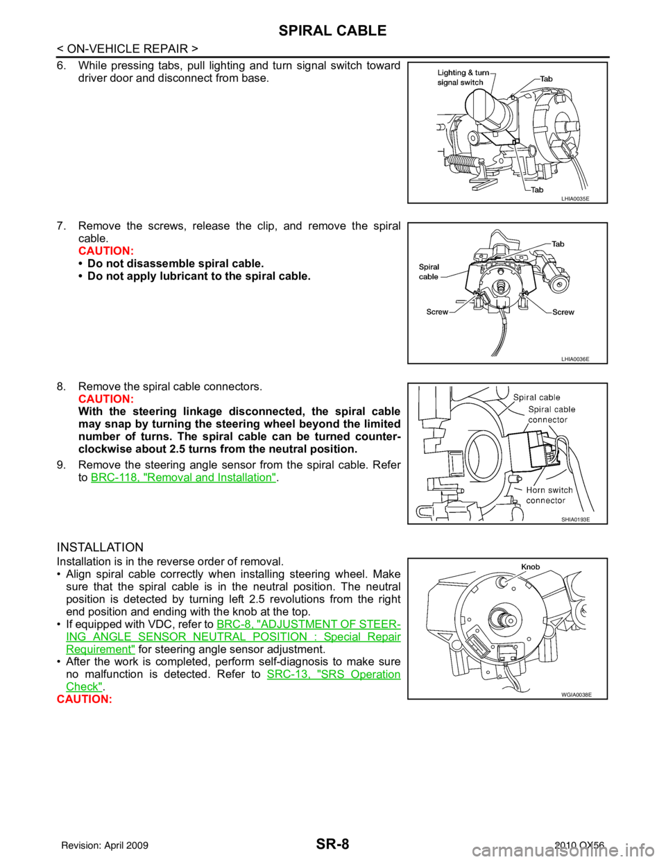
6. While pressing tabs, pull lighting and turn signal switch towarddriver door and disconnect from base.
7. Remove the screws, release the clip, and remove the spiral cable.
CAUTION:
• Do not disassemble spiral cable.
• Do not apply lubricant to the spiral cable.
8. Remove the spiral cable connectors. CAUTION:
With the steering linkage di sconnected, the spiral cable
may snap by turning the steer ing wheel beyond the limited
number of turns. The spiral cable can be turned counter-
clockwise about 2.5 turns fr om the neutral position.
9. Remove the steering angle sensor from the spiral cable. Refer to BRC-118, "
Removal and Installation".
INSTALLATION
Installation is in the reverse order of removal.
• Align spiral cable correctly when installing steering wheel. Make
sure that the spiral cable is in the neutral position. The neutral
position is detected by turning left 2.5 revolutions from the right
end position and ending with the knob at the top.
• If equipped with VDC, refer to BRC-8, "
ADJUSTMENT OF STEER-
ING ANGLE SENSOR NEUTRAL POSITION : Special Repair
Requirement" for steering angle sensor adjustment.
• After the work is completed, perform self-diagnosis to make sure no malfunction is detected. Refer to SRC-13, "
SRS Operation
Check".
CAUTION:
LHIA0035E
LHIA0036E
SHIA0193E
WGIA0038E
Revision: April 20092010 QX56
Page 3532 of 4210
SPIRAL CABLESR-9
< ON-VEHICLE REPAIR >
C
DE
F
G
I
J
K L
M A
B
SR
N
O P
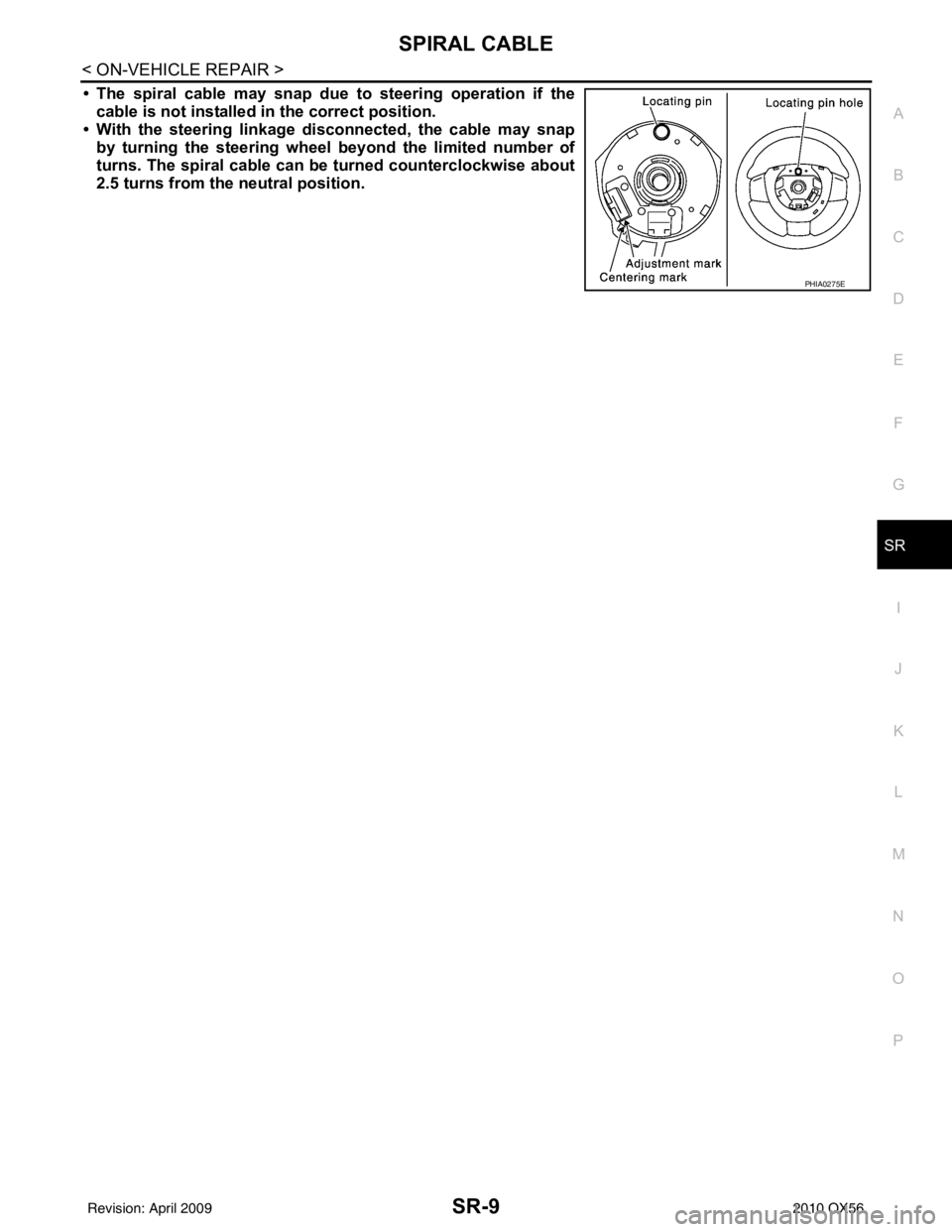
• The spiral cable may snap du e to steering operation if the
cable is not installed in the correct position.
• With the steering linkage disconnected, the cable may snap
by turning the steering wheel beyond the limited number of
turns. The spiral cable can be turned counterclockwise about
2.5 turns from the neutral position.
PHIA0275E
Revision: April 20092010 QX56
Page 3656 of 4210
ST-18
< REMOVAL AND INSTALLATION >
STEERING WHEEL
REMOVAL AND INSTALLATION
STEERING WHEEL
Removal and InstallationINFOID:0000000005147870
REMOVAL
1. Set the front wheels in the straight-ahead position.
2. Remove the driver air bag module. Refer to SR-5, "
Removal and Installation".
3. Disconnect steering wheel switches.
4. Remove the steering wheel center nut.
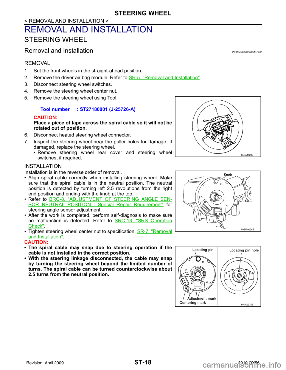
5. Remove the steering wheel using Tool.
CAUTION:
Place a piece of tape across the sp iral cable so it will not be
rotated out of position.
6. Disconnect heated steering wheel connector.
7. Inspect the steering wheel near the puller holes for damage. If damaged, replace the steering wheel.
• Remove steering wheel rear cover and steering wheelswitches, if required.
INSTALLATION
Installation is in the reverse order of removal.
• Align spiral cable correctly when installing steering wheel. Makesure that the spiral cable is in the neutral position. The neutral
position is detected by turning left 2.5 revolutions from the right
end position and ending with the knob at the top.
• Refer to BRC-8, "
ADJUSTMENT OF STEERING ANGLE SEN-
SOR NEUTRAL POSITION : Special Repair Requirement" for
steering angle sensor adjustment.
• After the work is completed, perform self-diagnosis to make sure no malfunction is detected. Refer to SRC-13, "
SRS Operation
Check".
• Tighten steering wheel center nut to specification. SR-7, "
Removal
and Installation".
CAUTION:
• The spiral cable may snap due to steering operation if the
cable is not installed in the correct position.
• With the steering linkage di sconnected, the cable may snap
by turning the steering wheel beyond the limited number of
turns. The spiral cable can be turned counterclockwise about
2.5 turns from the neutral position. Tool number : ST27180001 (J-25726-A)
SGIA1524J
WGIA0038E
PHIA0275E
Revision: April 20092010 QX56
Page 3882 of 4210
TRANSMISSION ASSEMBLYTM-187
< REMOVAL AND INSTALLATION >
CEF
G H
I
J
K L
M A
B
TM
N
O P
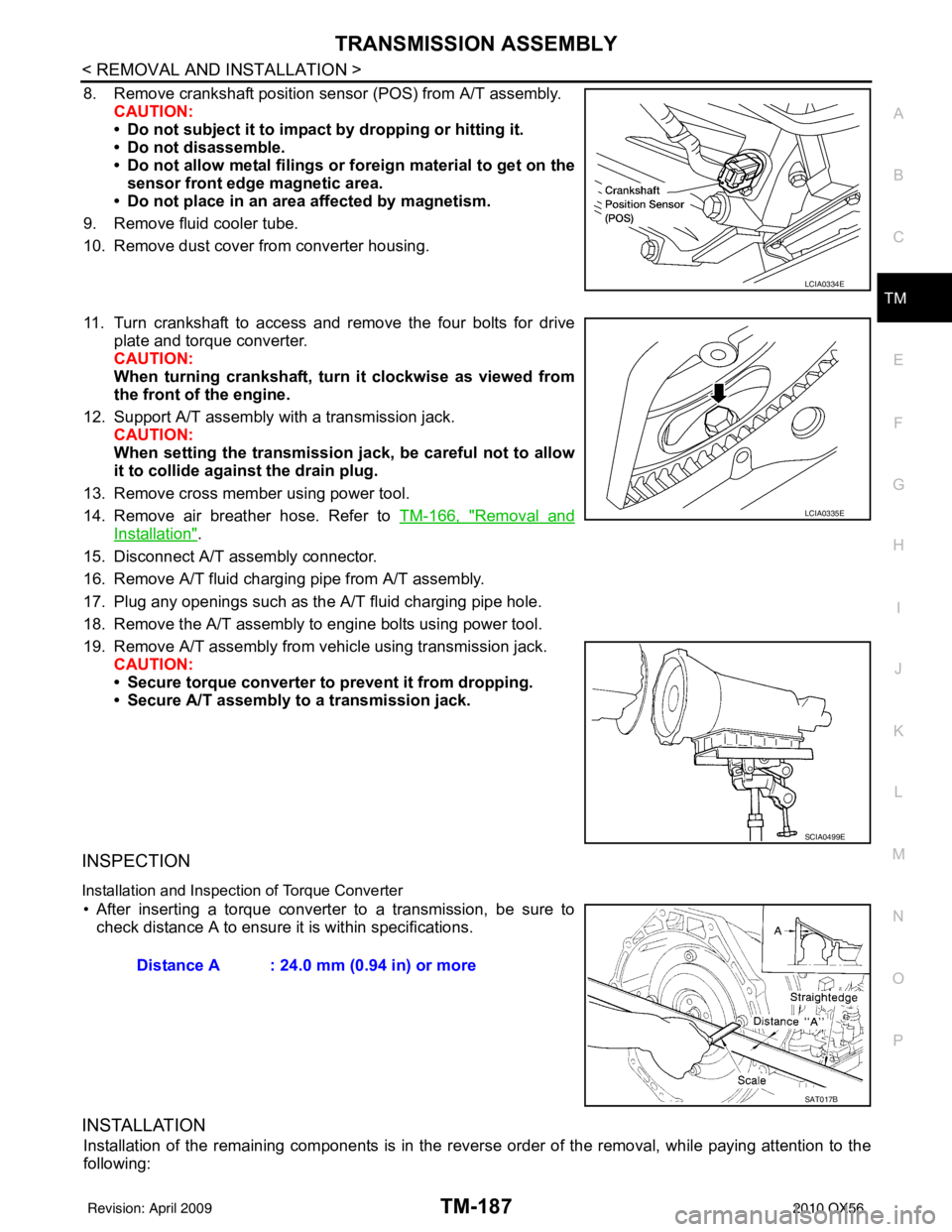
8. Remove crankshaft position sens or (POS) from A/T assembly.
CAUTION:
• Do not subject it to impact by dropping or hitting it.
• Do not disassemble.
• Do not allow metal filings or foreign material to get on the
sensor front edge magnetic area.
• Do not place in an area affected by magnetism.
9. Remove fluid cooler tube.
10. Remove dust cover from converter housing.
11. Turn crankshaft to access and remove the four bolts for drive plate and torque converter.
CAUTION:
When turning crankshaft, turn it clockwise as viewed from
the front of the engine.
12. Support A/T assembly with a transmission jack. CAUTION:
When setting the transmission jack, be careful not to allow
it to collide agai nst the drain plug.
13. Remove cross member using power tool.
14. Remove air breather hose. Refer to TM-166, "
Removal and
Installation".
15. Disconnect A/T assembly connector.
16. Remove A/T fluid charging pipe from A/T assembly.
17. Plug any openings such as the A/T fluid charging pipe hole.
18. Remove the A/T assembly to engine bolts using power tool.
19. Remove A/T assembly from vehicle using transmission jack. CAUTION:
• Secure torque converter to prevent it from dropping.
• Secure A/T assembly to a transmission jack.
INSPECTION
Installation and Inspection of Torque Converter
• After inserting a torque converter to a transmission, be sure to check distance A to ensure it is within specifications.
INSTALLATION
Installation of the remaining components is in the revers e order of the removal, while paying attention to the
following:
LCIA0334E
LCIA0335E
SCIA0499E
Distance A : 24.0 mm (0.94 in) or more
SAT017B
Revision: April 20092010 QX56
Page 3883 of 4210
TM-188
< REMOVAL AND INSTALLATION >
TRANSMISSION ASSEMBLY
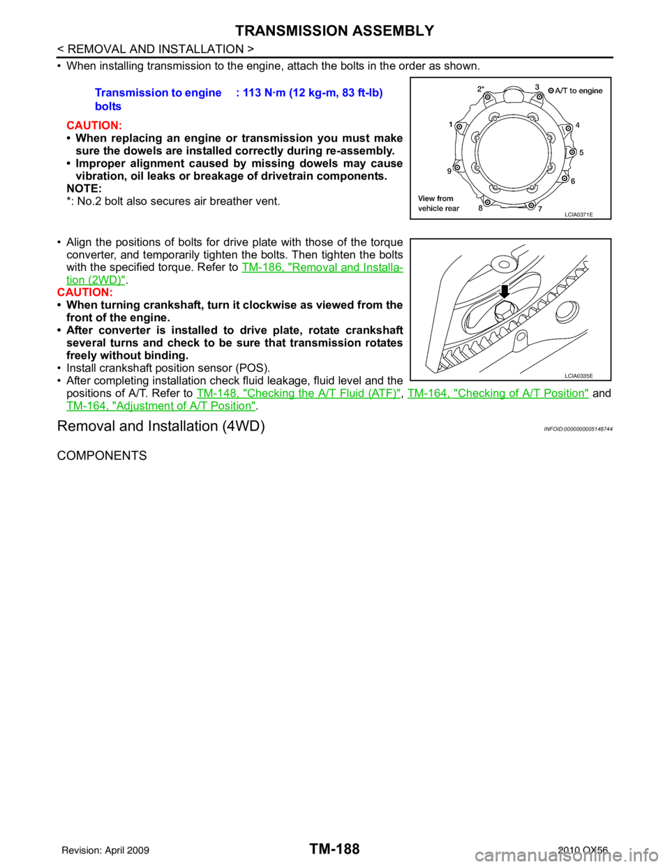
• When installing transmission to the engine, attach the bolts in the order as shown.CAUTION:
• When replacing an engine or transmission you must make
sure the dowels are installe d correctly during re-assembly.
• Improper alignment caused by missing dowels may cause
vibration, oil leaks or breakage of drivetrain components.
NOTE:
*: No.2 bolt also secures air breather vent.
• Align the positions of bolts for drive plate with those of the torque converter, and temporarily tighten the bolts. Then tighten the bolts
with the specified torque. Refer to TM-186, "
Removal and Installa-
tion (2WD)".
CAUTION:
• When turning crankshaft, turn it clockwise as viewed from the front of the engine.
• After converter is installed to drive plate, rotate crankshaft
several turns and check to be sure that transmission rotates
freely without binding.
• Install crankshaft pos ition sensor (POS).
• After completing installation check fluid leakage, fluid level and the
positions of A/T. Refer to TM-148, "
Checking the A/T Fluid (ATF)", TM-164, "Checking of A/T Position" and
TM-164, "
Adjustment of A/T Position".
Removal and Installation (4WD)INFOID:0000000005148744
COMPONENTS
Transmission to engine
bolts : 113 N·m (12 kg-m, 83 ft-lb)
LCIA0371E
LCIA0335E
Revision: April 20092010 QX56