clock INFINITI QX56 2010 Factory Service Manual
[x] Cancel search | Manufacturer: INFINITI, Model Year: 2010, Model line: QX56, Model: INFINITI QX56 2010Pages: 4210, PDF Size: 81.91 MB
Page 172 of 4210
ADP-158
< ECU DIAGNOSIS >
BCM (BODY CONTROL MODULE)
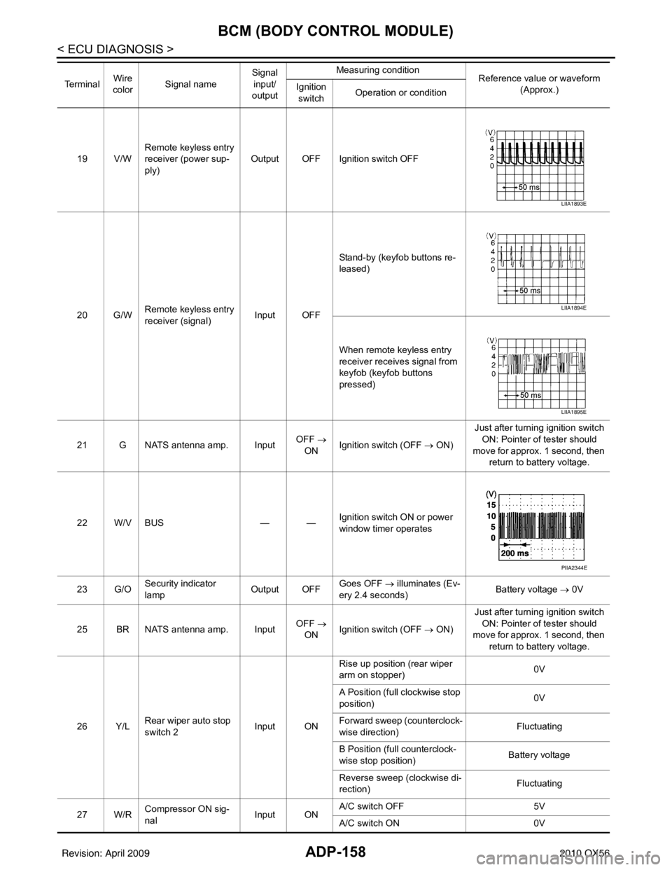
19 V/WRemote keyless entry
receiver (power sup-
ply) Output OFF Ignition switch OFF
20 G/W Remote keyless entry
receiver (signal) Input OFFStand-by (keyfob buttons re-
leased)
When remote keyless entry
receiver receives signal from
keyfob (keyfob buttons
pressed)
21 G NATS antenna amp. Input OFF
→
ON Ignition switch (OFF
→ ON)Just after turning ignition switch
ON: Pointer of tester should
move for approx. 1 second, then return to battery voltage.
22 W/V BUS — —Ignition switch ON or power
window timer operates
23 G/O Security indicator
lamp Output OFF
Goes OFF
→ illuminates (Ev-
ery 2.4 seconds) Battery voltage
→ 0V
25 BR NATS antenna amp. Input OFF
→
ON Ignition switch (OFF
→ ON)Just after turning ignition switch
ON: Pointer of tester should
move for approx. 1 second, then return to battery voltage.
26 Y/L Rear wiper auto stop
switch 2 Input ONRise up position (rear wiper
arm on stopper)
0V
A Position (full clockwise stop
position) 0V
Forward sweep (counterclock-
wise direction) Fluctuating
B Position (full counterclock-
wise stop position) Battery voltage
Reverse sweep (clockwise di-
rection) Fluctuating
27 W/R Compressor ON sig-
nal Input ONA/C switch OFF
5V
A/C switch ON 0V
Te r m i n a l
Wire
color Signal name Signal
input/
output Measuring condition
Reference value or waveform
(Approx.)
Ignition
switch Operation or condition
LIIA1893E
LIIA1894E
LIIA1895E
PIIA2344E
Revision: April 20092010 QX56
Page 174 of 4210
ADP-160
< ECU DIAGNOSIS >
BCM (BODY CONTROL MODULE)
44 ORear wiper auto stop
switch 1 Input ONRise up position (rear wiper
arm on stopper)
0V
A Position (full clockwise stop
position) Battery voltage
Forward sweep (counterclock-
wise direction) Fluctuating
B Position (full counterclock-
wise stop position) 0V
Reverse sweep (clockwise di-
rection) Fluctuating
47 SB Front door switch LH Input OFF ON (open)
0V
OFF (closed) Battery voltage
48 R/Y Rear door switch LH Input OFF ON (open)
0V
OFF (closed) Battery voltage
49 R Cargo lamp Output OFFAny door open (ON)
0V
All doors closed (OFF) Battery voltage
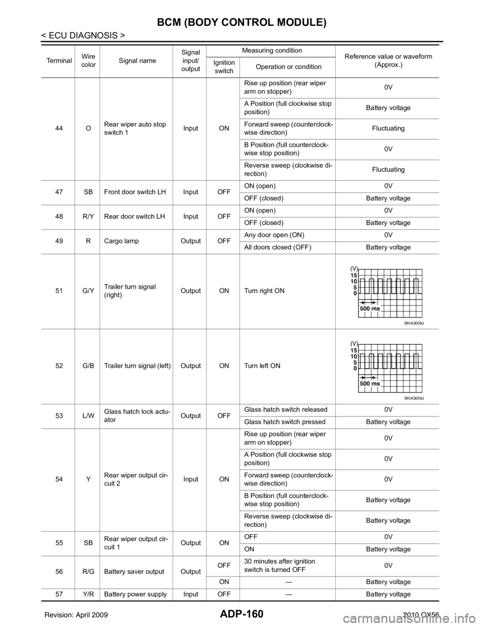
51 G/Y Trailer turn signal
(right) Output ON Turn right ON
52 G/B Trailer turn signal (l eft) Output ON Turn left ON
53 L/W Glass hatch lock actu-
ator
Output OFFGlass hatch switch released
0V
Glass hatch switch pressed Battery voltage
54 Y Rear wiper output cir-
cuit 2 Input ONRise up position (rear wiper
arm on stopper)
0V
A Position (full clockwise stop
position) 0V
Forward sweep (counterclock-
wise direction) 0V
B Position (full counterclock-
wise stop position) Battery voltage
Reverse sweep (clockwise di-
rection) Battery voltage
55 SB Rear wiper output cir-
cuit 1 Output ONOFF
0V
ON Battery voltage
56 R/G Battery saver output Output OFF
30 minutes after ignition
switch is turned OFF 0V
ON — Battery voltage
57 Y/R Battery power supply Input OFF —Battery voltage
Te r m i n a l
Wire
color Signal name Signal
input/
output Measuring condition
Reference value or waveform
(Approx.)
Ignition
switch Operation or condition
SKIA3009J
SKIA3009J
Revision: April 20092010 QX56
Page 225 of 4210
![INFINITI QX56 2010 Factory Service Manual AV-28
< FUNCTION DIAGNOSIS >[AUDIO SYSTEM]
DIAGNOSIS SYSTEM (AV CONTROL UNIT)
OPERATION PROCEDURE
1. Start the engine.
2. Turn the audio system off.
3. While pressing the “SETTING” button, turn t INFINITI QX56 2010 Factory Service Manual AV-28
< FUNCTION DIAGNOSIS >[AUDIO SYSTEM]
DIAGNOSIS SYSTEM (AV CONTROL UNIT)
OPERATION PROCEDURE
1. Start the engine.
2. Turn the audio system off.
3. While pressing the “SETTING” button, turn t](/img/42/57032/w960_57032-224.png)
AV-28
< FUNCTION DIAGNOSIS >[AUDIO SYSTEM]
DIAGNOSIS SYSTEM (AV CONTROL UNIT)
OPERATION PROCEDURE
1. Start the engine.
2. Turn the audio system off.
3. While pressing the “SETTING” button, turn the volume control
dial counterclockwise 30 clicks or more.
CONFIRMATION/
ADJUSTMENT Display diagnosis
Color spectrum bar Color tone of the screen can be checked by the display of a color bar.
Gradation bar Shading of the screen can be checked by the display of a gray scale.
Touch panel
• Touch panel calibration
• Touch panel response check
Vehicle signals The following vehicle signals are analyzed: Vehicle speed signal, park-
ing brake signal, light signal, ignition switch signal, and reverse signal.
Speaker test Connection can be checked by sending a test tone to each speaker.
Navigation Steering angle ad-
justment
Confirm/adjust the steering angle when there is a difference between
the displayed vehicle mark turning angle and actual.
Speed calibration Confirm/adjust the speed calibration when there is a difference between
the displayed vehicle mark location and actual.
XM SAT subscrip-
tion status Check the subscription status of the XM NAV Traffic subsription.
Error history Diagnosis results previously stored in the memory are displayed in this
mode.
Synchronize FES clock Turns FES (Familly Entertainment System) clock synchronization func-
tion ON/OFF.
Vehicle CAN diagnosis The transmitting/receiving of CAN communication can be monitored.
AV COMM diagnosis The transmitting/receiving of AV communication can be monitored.
Handsfree phone Handsfree volume
adjustment
Adjust handsfree volume (low, medium, high).
Voice microphone
test Test microphone operation.
Delete handsfree
memory Erase handsfree system memory.
Bluetooth Confirm/Change
passkey
Confirm and change the Bluetooth passkey
Confirm/Change
device name Confirm and change a device name stored in Bluetooth.
SAT Change channel
Any necessary channels required to recieve traffic information from the
satellite radio system can be set.
Change applica-
tion ID Any application ID’s required to recieve traffic information from the sat-
ellite radio system can be set.
Diag Not used.
Delete unit connection log Erase the error history and connection history of the unit.
Initialize settings All audio settings are reset to default levels.
Mode
Description
ALNIA0446GB
Revision: April 20092010 QX56
Page 431 of 4210
![INFINITI QX56 2010 Factory Service Manual BCS
BCM (BODY CONTROL MODULE)BCS-45
< ECU DIAGNOSIS > [BCM]
C
D
E
F
G H
I
J
K L
B A
O P
N19 V/W
Remote keyless entry
receiver (power sup-
ply) Output OFF Ignition switch OFF
20 G/W Remote keyless ent INFINITI QX56 2010 Factory Service Manual BCS
BCM (BODY CONTROL MODULE)BCS-45
< ECU DIAGNOSIS > [BCM]
C
D
E
F
G H
I
J
K L
B A
O P
N19 V/W
Remote keyless entry
receiver (power sup-
ply) Output OFF Ignition switch OFF
20 G/W Remote keyless ent](/img/42/57032/w960_57032-430.png)
BCS
BCM (BODY CONTROL MODULE)BCS-45
< ECU DIAGNOSIS > [BCM]
C
D
E
F
G H
I
J
K L
B A
O P
N19 V/W
Remote keyless entry
receiver (power sup-
ply) Output OFF Ignition switch OFF
20 G/W Remote keyless entry
receiver (signal) Input OFFStand-by (keyfob buttons re-
leased)
When remote keyless entry
receiver receives signal from
keyfob (keyfob buttons
pressed)
21 G NATS antenna amp. Input OFF
→
ON Ignition switch (OFF → ON) Just after turning ignition switch
ON: Pointer of tester should
move for approx. 1 second, then return to battery voltage.
22 W/V BUS — —Ignition switch ON or power
window timer operates
23 G/O Security indicator
lamp Output OFF
Goes OFF
→ illuminates (Ev-
ery 2.4 seconds) Battery voltage
→ 0V
25 BR NATS antenna amp. Input OFF
→
ON Ignition switch (OFF → ON) Just after turning ignition switch
ON: Pointer of tester should
move for approx. 1 second, then return to battery voltage.
26 Y/L Rear wiper auto stop
switch 2 Input ONRise up position (rear wiper
arm on stopper)
0V
A Position (full clockwise stop
position) 0V
Forward sweep (counterclock-
wise direction) Fluctuating
B Position (full counterclock-
wise stop position) Battery voltage
Reverse sweep (clockwise di-
rection) Fluctuating
27 W/R Compressor ON sig-
nal Input ONA/C switch OFF
5V
A/C switch ON 0V
Te r m i n a l
Wire
color Signal name Signal
input/
output Measuring condition
Reference value or waveform
(Approx.)
Ignition
switch Operation or condition
LIIA1893E
LIIA1894E
LIIA1895E
PIIA2344E
Revision: April 20092010 QX56
Page 433 of 4210
![INFINITI QX56 2010 Factory Service Manual BCS
BCM (BODY CONTROL MODULE)BCS-47
< ECU DIAGNOSIS > [BCM]
C
D
E
F
G H
I
J
K L
B A
O P
N44 O
Rear wiper auto stop
switch 1 Input ONRise up position (rear wiper
arm on stopper)
0V
A Position (full c INFINITI QX56 2010 Factory Service Manual BCS
BCM (BODY CONTROL MODULE)BCS-47
< ECU DIAGNOSIS > [BCM]
C
D
E
F
G H
I
J
K L
B A
O P
N44 O
Rear wiper auto stop
switch 1 Input ONRise up position (rear wiper
arm on stopper)
0V
A Position (full c](/img/42/57032/w960_57032-432.png)
BCS
BCM (BODY CONTROL MODULE)BCS-47
< ECU DIAGNOSIS > [BCM]
C
D
E
F
G H
I
J
K L
B A
O P
N44 O
Rear wiper auto stop
switch 1 Input ONRise up position (rear wiper
arm on stopper)
0V
A Position (full clockwise stop
position) Battery voltage
Forward sweep (counterclock-
wise direction) Fluctuating
B Position (full counterclock-
wise stop position) 0V
Reverse sweep (clockwise di-
rection) Fluctuating
47 SB Front door switch LH Input OFF ON (open)
0V
OFF (closed) Battery voltage
48 R/Y Rear door switch LH Input OFF ON (open)
0V
OFF (closed) Battery voltage
49 R Cargo lamp Output OFFAny door open (ON)
0V
All doors closed (OFF) Battery voltage
51 G/Y Trailer turn signal
(right) Output ON Turn right ON
52 G/B Trailer turn signal (left) Output ON Turn left ON
53 L/W Glass hatch lock actu-
ator
Output OFFGlass hatch switch released
0V
Glass hatch switch pressed Battery voltage
54 Y Rear wiper output cir-
cuit 2 Input ONRise up position (rear wiper
arm on stopper)
0V
A Position (full clockwise stop
position) 0V
Forward sweep (counterclock-
wise direction) 0V
B Position (full counterclock-
wise stop position) Battery voltage
Reverse sweep (clockwise di-
rection) Battery voltage
55 SB Rear wiper output cir-
cuit 1 Output ONOFF
0V
ON Battery voltage
56 R/G Battery saver output Output OFF
30 minutes after ignition
switch is turned OFF 0V
ON — Battery voltage
57 Y/R Battery power supply Input OFF —Battery voltage
Te r m i n a l
Wire
color Signal name Signal
input/
output Measuring condition
Reference value or waveform
(Approx.)
Ignition
switch Operation or condition
SKIA3009J
SKIA3009J
Revision: April 20092010 QX56
Page 458 of 4210
BRAKE TUBE AND HOSEBR-13
< BASIC INSPECTION >
C
DE
G H
I
J
K L
M A
B
BR
N
O P
BRAKE TUBE AND HOSE
Hydraulic CircuitINFOID:0000000005147897
CAUTION:
• All hoses and piping (tubes) must be fr ee from excessive bending, twisting and pulling.
• Make sure there is no interference with other parts when turning the steering wheel both clockwise
and counterclockwise.
• The brake piping is an important safety part. If a brake fluid leak is detected, always disassemble the
parts. Replace applicable part with a new one, if necessary.
• Be careful not to splash brake fluid on painted areas; it may cause paint damage. If brake fluid is
splashed on painted areas, wash it away with water immediately.
• Do not bend or twist brake hose sharply, or strongly pull it.
• When removing components, cover connections so that no dirt, dust, or other foreign matter gets in.
• Refill with new specified brake fluid. Refer to MA-13, "
Fluids and Lubricants".
• Do not reuse drained brake fluid.
FRONT BRAKE
FRONT BRAKE : InspectionINFOID:0000000005147898
INSPECTION AFTER REMOVAL
CAUTION:
Brake tubes and hoses are important safety parts. Always disassemble the parts and retighten their fit-
tings, if a brake fluid leak is det ected. Replace applicable part with a new one, if damaged part is
detected.
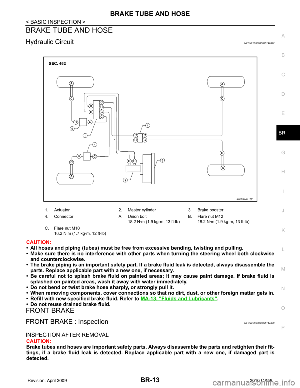
1. Actuator 2. Master cylinder3. Brake booster
4. Connector A. Union bolt
18.2 N·m (1.9 kg-m, 13 ft-lb) B. Flare nut M12
18.2 N·m (1.9 kg-m, 13 ft-lb)
C. Flare nut M10 16.2 N·m (1.7 kg-m, 12 ft-lb)
AWFIA0411ZZ
Revision: April 20092010 QX56
Page 460 of 4210
BRAKE PEDALBR-15
< ON-VEHICLE MAINTENANCE >
C
DE
G H
I
J
K L
M A
B
BR
N
O P
ON-VEHICLE MAINTENANCE
BRAKE PEDAL
Inspection and AdjustmentINFOID:0000000005147900
INSPECTION
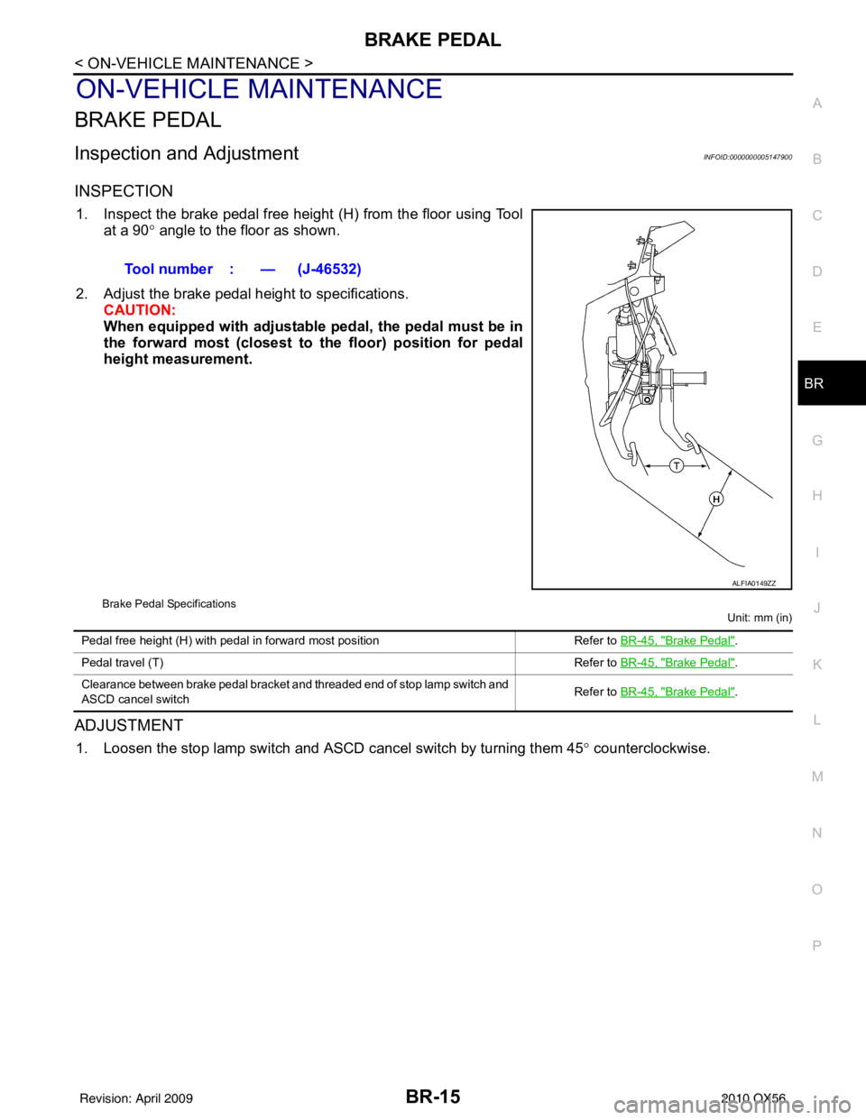
1. Inspect the brake pedal free height (H) from the floor using Tool at a 90 ° angle to the floor as shown.
2. Adjust the brake pedal height to specifications. CAUTION:
When equipped with adjustable pedal, the pedal must be in
the forward most (closest to th e floor) position for pedal
height measurement.
Brake Pedal Specifications
Unit: mm (in)
ADJUSTMENT
1. Loosen the stop lamp switch and ASCD cancel switch by turning them 45° counterclockwise.
Tool number : — (J-46532)
ALFIA0149ZZ
Pedal free height (H) with pedal in forward most position
Refer to BR-45, "Brake Pedal".
Pedal travel (T) Refer to BR-45, "
Brake Pedal".
Clearance between brake pedal bracket and threaded end of stop lamp switch and
ASCD cancel switch Refer to
BR-45, "
Brake Pedal".
Revision: April 20092010 QX56
Page 461 of 4210
BR-16
< ON-VEHICLE MAINTENANCE >
BRAKE PEDAL
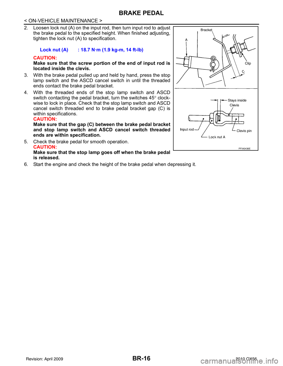
2. Loosen lock nut (A) on the input rod, then turn input rod to adjustthe brake pedal to the specified height. When finished adjusting,
tighten the lock nut (A) to specification.
CAUTION:
Make sure that the screw portion of the end of input rod is
located inside the clevis.
3. With the brake pedal pulled up and held by hand, press the stop lamp switch and the ASCD cancel switch in until the threaded
ends contact the brake pedal bracket.
4. With the threaded ends of the stop lamp switch and ASCD switch contacting the pedal bracket, turn the switches 45 ° clock-
wise to lock in place. Check that the stop lamp switch and ASCD
cancel switch threaded end to brake pedal bracket gap (C) is
within specifications.
CAUTION:
Make sure that the gap (C) between the brake pedal bracket
and stop lamp switch and ASCD cancel switch threaded
ends are within specification.
5. Check the brake pedal for smooth operation. CAUTION:
Make sure that the stop lamp goes off when the brake pedal
is released.
6. Start the engine and check the height of the brake pedal when depressing it. Lock nut (A) : 18.7 N·m (1.9 kg-m, 14 ft-lb)
PFIA0436E
Revision: April 20092010 QX56
Page 466 of 4210
BRAKE TUBE AND HOSEBR-21
< ON-VEHICLE REPAIR >
C
DE
G H
I
J
K L
M A
B
BR
N
O P
BRAKE TUBE AND HOSE
Hydraulic CircuitINFOID:0000000005147905
CAUTION:
• All hoses and piping (tubes) must be fr ee from excessive bending, twisting and pulling.
• Make sure there is no interference with other parts when turning the steering wheel both clockwise
and counterclockwise.
• The brake piping is an important safety part. If a brake fluid leak is detected, always disassemble the
parts. Replace applicable part with a new one, if necessary.
• Be careful not to splash brake fluid on painted areas; it may cause paint damage. If brake fluid is
splashed on painted areas, wash it away with water immediately.
• Do not bend or twist brake hose sharply, or strongly pull it.
• When removing components, cover connections so that no dirt, dust, or other foreign matter gets in.
• Refill with new specified brake fluid. Refer to MA-13, "
Fluids and Lubricants".
• Do not reuse drained brake fluid.
Removal and Installation of Fr ont Brake Piping and Brake HoseINFOID:0000000005147906
REMOVAL
1. Remove front wheel and tire using power tool.
2. Remove brake reservoir cap.
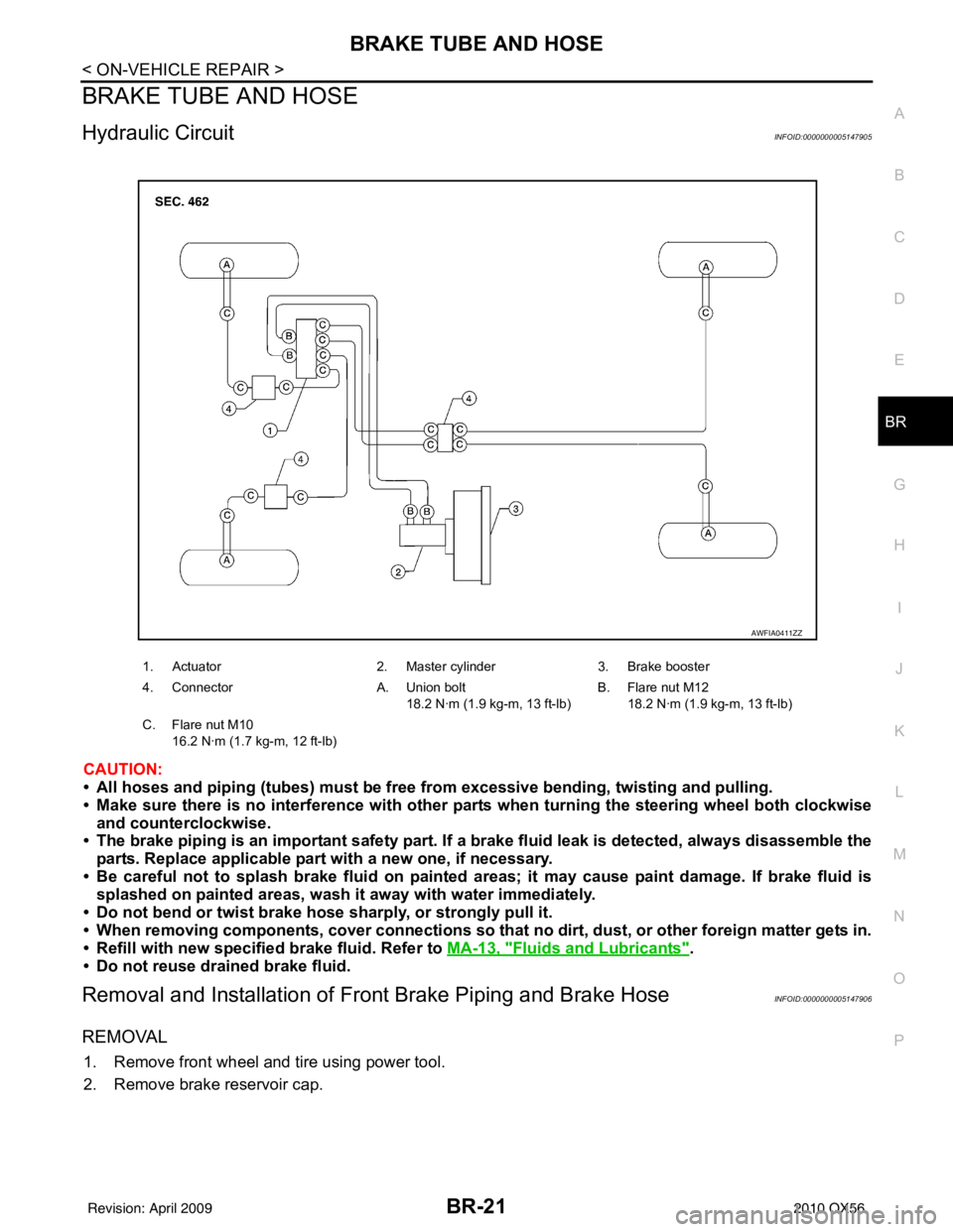
1. Actuator 2. Master cylinder3. Brake booster
4. Connector A. Union bolt
18.2 N·m (1.9 kg-m, 13 ft-lb) B. Flare nut M12
18.2 N·m (1.9 kg-m, 13 ft-lb)
C. Flare nut M10 16.2 N·m (1.7 kg-m, 12 ft-lb)
AWFIA0411ZZ
Revision: April 20092010 QX56
Page 677 of 4210
CCS-8
< BASIC INSPECTION >
INSPECTION AND ADJUSTMENT
NOTE:
If the adjustment screen does not appear on CONSULT-III 10 sec. after touching “LASER BEAM ADJUST”
screen, the following causes may be considered:
• Target is not set accurately.
• There is not enough space beside the target.
• Deformation of vehicle or inappropriate installation of sensor. Sensor may be installed out of the adjustablerange.
• The area is not suitable for the adjustment work.
• ICC sensor is not clean.
>> GO TO 2
2.LASER BEAM AIMING CONFIRMATION
After the CONSULT-III displays “ADJ UST THE VERTICAL OF LASER BEAM AIMING” turn the vertical adjust-
ing screw until “U/D CORRECT” value is set in the range of ±4.
NOTE:
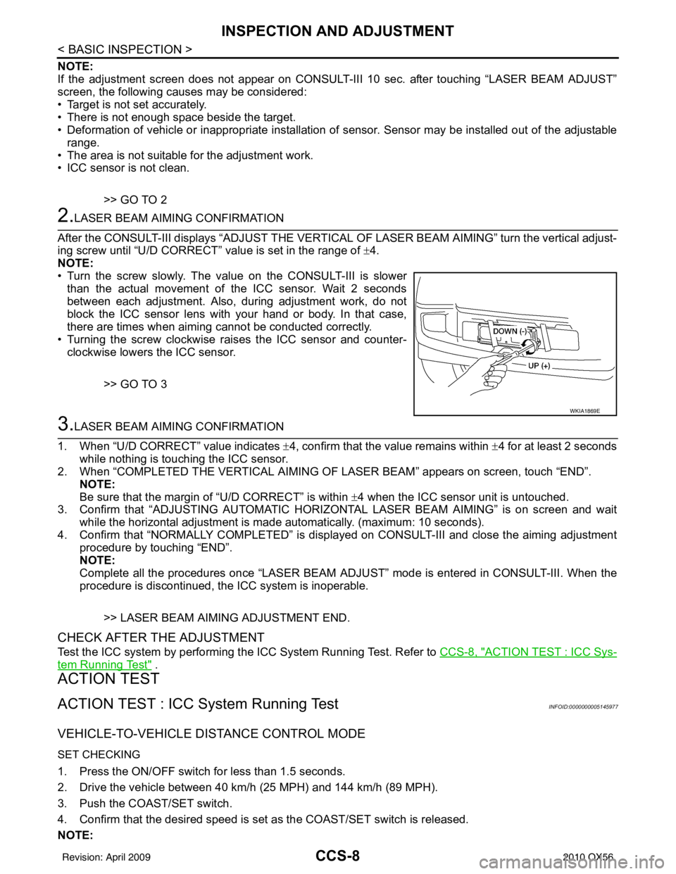
• Turn the screw slowly. The value on the CONSULT-III is slower
than the actual movement of the ICC sensor. Wait 2 seconds
between each adjustment. Also, during adjustment work, do not
block the ICC sensor lens with your hand or body. In that case,
there are times when aiming cannot be conducted correctly.
• Turning the screw clockwise raises the ICC sensor and counter- clockwise lowers the ICC sensor.
>> GO TO 3
3.LASER BEAM AIMING CONFIRMATION
1. When “U/D CORRECT” value indicates ±4, confirm that the value remains within ±4 for at least 2 seconds
while nothing is touching the ICC sensor.
2. When “COMPLETED THE VERTICAL AIMING OF LASER BEAM” appears on screen, touch “END”.
NOTE:
Be sure that the margin of “U/D CORRECT” is within ±4 when the ICC sensor unit is untouched.
3. Confirm that “ADJUSTING AUTOMATIC HORIZONTAL LASER BEAM AIMING” is on screen and wait
while the horizontal adjustment is made automatically. (maximum: 10 seconds).
4. Confirm that “NORMALLY COMPLETED” is displayed on CONSULT-III and close the aiming adjustment procedure by touching “END”.
NOTE:
Complete all the procedures once “LASER BEAM AD JUST” mode is entered in CONSULT-III. When the
procedure is discontinued, the ICC system is inoperable.
>> LASER BEAM AIMING ADJUSTMENT END.
CHECK AFTER THE ADJUSTMENT
Test the ICC system by performing the ICC System Running Test. Refer to CCS-8, "ACTION TEST : ICC Sys-
tem Running Test" .
ACTION TEST
ACTION TEST : ICC System Running TestINFOID:0000000005145977
VEHICLE-TO-VEHICLE DISTANCE CONTROL MODE
SET CHECKING
1. Press the ON/OFF switch for less than 1.5 seconds.
2. Drive the vehicle between 40 km/h (25 MPH) and 144 km/h (89 MPH).
3. Push the COAST/SET switch.
4. Confirm that the desired speed is set as the COAST/SET switch is released.
NOTE:
WKIA1869E
Revision: April 20092010 QX56