wheel alignment INFINITI QX56 2010 Factory Service Manual
[x] Cancel search | Manufacturer: INFINITI, Model Year: 2010, Model line: QX56, Model: INFINITI QX56 2010Pages: 4210, PDF Size: 81.91 MB
Page 5 of 4210

QUICK REFERENCE CHART: QX56
2010
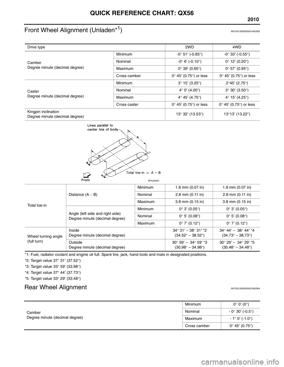
Front Wheel Alignment (Unladen*1)INFOID:0000000001842582
*1: Fuel, radiator coolant and engine oil full. Spare tire, jack, hand tools and mats in designated positions.
*2: Target value 37° 31 ′ (37.52 °)
*3: Target value 33 ° 59 ′ (33.98 °)
*4: Target value 37 ° 44 ′ (37.73 °)
*5: Target value 33 ° 29 ′ (33.48 °)
Rear Wheel AlignmentINFOID:0000000001842584
Drive type 2WD 4WD
Camber
Degree minute (decimal degree) Minimum -0
° 51 ′ (-0.85 °)-0 ° 33 ′ (-0.55 °)
Nominal -0 ° 6 ′ (-0.10 °)0 ° 12 ′ (0.20 °)
Maximum 0 ° 39 ′ (0.65 °)0 ° 57 ′ (0.95 °)
Cross camber 0 ° 45 ′ (0.75 °) or less 0 ° 45 ′ (0.75 °) or less
Caster
Degree minute (decimal degree) Minimum 3
° 15 ′ (3.25 °)2 °45 ′ (2.75 °)
Nominal 4 ° 0 ′ (4.00 °)3 ° 30 ′ (3.50 °)
Maximum 4 ° 45 ′ (4.75 °)4 ° 15 ′ (4.25 °)
Cross caster 0 ° 45 ′
(0.75 °) or less 0 ° 45 ′ (0.75 °) or less
Kingpin inclination
Degree minute (decimal degree) 13
° 32 ′ (13.53 °)13 °13 ′ (13.22 °)
Total toe-in Distance (A
− B) Minimum 1.8 mm (0.07 in) 1.8 mm (0.07 in)
Nominal 2.8 mm (0.11 in) 2.8 mm (0.11 in)
Maximum 3.8 mm (0.15 in) 3.8 mm (0.15 in)
Angle (left side and right side)
Degree minute (decimal degree) Minimum 0
° 3 ′ (0.05 °)0 ° 3 ′ (0.05 °)
Nominal 0 ° 5 ′ (0.08 °)0 ° 5 ′ (0.08 °)
Maximum 0 ° 7 ′ (0.12 °)0 ° 7 ′ (0.12 °)
Wheel turning angle
(full turn) Inside
Degree minute (decimal degree)
34
° 31 ′ – 38 ° 31 ′ *2
(34.52 ° – 38.52 °) 34
° 44 ′ – 38 ° 44 ′ *4
(34.73 ° – 38.73
° )
Outside
Degree minute (decimal degree) 30
° 59 ′ – 34 ° 59 ′ *3
(30.98 ° – 34.98 °) 30
° 29 ′ – 34 ° 29 ′ *5
(30.48 ° – 34.48 °)
SFA234AC
Camber
Degree minute (decimal degree) Minimum 0
° 0 ′ (0 °)
Nominal - 0 ° 30 ′ (-0.5 °)
Maximum - 1 ° 0 ′ (-1.0 °)
Cross camber 0 ° 45 ′ (0.75 °)
Page 500 of 4210
![INFINITI QX56 2010 Factory Service Manual BRC-8
< BASIC INSPECTION >[VDC/TCS/ABS]
INSPECTION AND ADJUSTMENT
INSPECTION AND ADJUSTMENT
ADDITIONAL SERVICE WHEN
REPLACING CONTROL UNIT
ADDITIONAL SERVICE WHEN REPL ACING CONTROL UNIT : Descriptio INFINITI QX56 2010 Factory Service Manual BRC-8
< BASIC INSPECTION >[VDC/TCS/ABS]
INSPECTION AND ADJUSTMENT
INSPECTION AND ADJUSTMENT
ADDITIONAL SERVICE WHEN
REPLACING CONTROL UNIT
ADDITIONAL SERVICE WHEN REPL ACING CONTROL UNIT : Descriptio](/img/42/57032/w960_57032-499.png)
BRC-8
< BASIC INSPECTION >[VDC/TCS/ABS]
INSPECTION AND ADJUSTMENT
INSPECTION AND ADJUSTMENT
ADDITIONAL SERVICE WHEN
REPLACING CONTROL UNIT
ADDITIONAL SERVICE WHEN REPL ACING CONTROL UNIT : Description
INFOID:0000000005147940
After replacing the ABS actuator and electric unit (control unit), perform the following procedures:
• Neutral position adjustment for the steering angle sensor
• Calibration of the decel G sensor
ADDITIONAL SERVICE WHEN REPLACING CONTROL UNIT : Special Repair Re-
quirement
INFOID:0000000005147941
1.PERFORM THE NEUTRAL POSITION ADJUST MENT FOR THE STEERING ANGLE SENSOR
Perform the neutral position adjustm ent for the steering angle sensor.
>> Refer to BRC-8, "
ADJUSTMENT OF STEERING ANGLE SENSOR NEUTRAL POSITION : Spe-
cial Repair Requirement", GO TO 2
2.PERFORM CALIBRATION OF THE DECEL G SENSOR
Perform calibration of the decel G sensor.
>> Refer to BRC-9, "
CALIBRATION OF DECEL G SENSOR : Special Repair Requirement".
ADJUSTMENT OF STEERING ANGL E SENSOR NEUTRAL POSITION
ADJUSTMENT OF STEERING ANGLE SENSOR NEUTRAL POSITION : Description
INFOID:0000000005147942
Refer to the table below to determine if adjustment of steering angle sensor neutral position is required.
×: Required –: Not required
ADJUSTMENT OF STEERING ANGLE SENS OR NEUTRAL POSITION : Special Re-
pair Requirement
INFOID:0000000005147943
ADJUSTMENT OF STEERING ANGLE SENSOR NEUTRAL POSITION
CAUTION:
To adjust neutral position of steering angl e sensor, make sure to use CONSULT-III
(Adjustment cannot be done without CONSULT-III)
1.ALIGN THE VEHICLE STATUS
Stop vehicle with front wheels in straight-ahead position.
Situation Adjustment of steering angle sensor neutral position
Removing/Installing ABS actuator and electric unit (control unit) —
Replacing ABS actuator and electric unit (control unit) ×
Removing/Installing steering angle sensor ×
Replacing steering angle sensor ×
Removing/Installing steering components ×
Replacing steering components ×
Removing/Installing suspension components ×
Replacing suspension components ×
Change tires to new ones —
Tire rotation —
Adjusting wheel alignment ×
Battery disconnection ×
Revision: April 20092010 QX56
Page 501 of 4210
![INFINITI QX56 2010 Factory Service Manual INSPECTION AND ADJUSTMENTBRC-9
< BASIC INSPECTION > [VDC/TCS/ABS]
C
D
E
G H
I
J
K L
M A
B
BRC
N
O P
>> GO TO 2
2.PERFORM THE NEUTRAL POSITION ADJUST MENT FOR THE STEERING ANGLE SENSOR
1. On the CONSUL INFINITI QX56 2010 Factory Service Manual INSPECTION AND ADJUSTMENTBRC-9
< BASIC INSPECTION > [VDC/TCS/ABS]
C
D
E
G H
I
J
K L
M A
B
BRC
N
O P
>> GO TO 2
2.PERFORM THE NEUTRAL POSITION ADJUST MENT FOR THE STEERING ANGLE SENSOR
1. On the CONSUL](/img/42/57032/w960_57032-500.png)
INSPECTION AND ADJUSTMENTBRC-9
< BASIC INSPECTION > [VDC/TCS/ABS]
C
D
E
G H
I
J
K L
M A
B
BRC
N
O P
>> GO TO 2
2.PERFORM THE NEUTRAL POSITION ADJUST MENT FOR THE STEERING ANGLE SENSOR
1. On the CONSULT-III screen, touch “WORK SUPP ORT” and “ST ANG SEN ADJUSTMENT” in order.
2. Touch “START”. CAUTION:
Do not touch steering wheel whil e adjusting steering angle sensor.
3. After approximately 10 seconds, touch “END”. NOTE:
After approximately 60 seconds, it ends automatically.
4. Turn ignition switch OFF, then turn it ON again. CAUTION:
Be sure to perform above operation.
>> GO TO 3
3.CHECK DATA MONITOR
1. Run vehicle with front wheels in straight-ahead position, then stop.
2. Select “DATA MONITOR”. Then make sure “STR ANGLE SIG” is within 0 ±2.5 °.
Is the steering angle within the specified range?
YES >> GO TO 4
NO >> Perform the neutral position adjustment fo r the steering angle sensor again, GO TO 1
4.ERASE THE SELF-DIAGNOSIS MEMORY
Erase the self-diagnosis memory of the ABS ac tuator and electric unit (control unit) and ECM.
• ABS actuator and electric unit (control unit): Refer to BRC-23, "
CONSULT-III Function (ABS)".
• ECM: Refer to EC-63, "
CONSULT-III Function (ENGINE)".
Are the memories erased?
YES >> Inspection End
NO >> Check the items indica ted by the self-diagnosis.
CALIBRATION OF DECEL G SENSOR
CALIBRATION OF DECEL G SENSOR : DescriptionINFOID:0000000005147944
Refer to the table below to determine if calibration of the decel G sensor is required.
×: Required –: Not required
CALIBRATION OF DECEL G SENSOR : Special Repair RequirementINFOID:0000000005147945
CALIBRATION OF DECEL G SENSOR
CAUTION:
To calibrate the decel G sensor, make sure to use CONSULT-III
Situation Calibration of decel G sensor
Removing/Insta lling ABS actuator and electr ic unit (control unit) —
Replacing ABS actuator and elec tric unit (control unit) ×
Removing/Installing steering angle sensor ×
Replacing steering angle sensor ×
Removing/Installing steering components ×
Replacing steering components ×
Removing/Installing suspension components ×
Replacing suspension components ×
Change tires to new ones —
Tire rotation —
Adjusting wheel alignment ×
Revision: April 20092010 QX56
Page 612 of 4210

BRM-1
BODY EXTERIOR, DOORS, ROOF & VEHICLE SECURITY
C
DE
F
G H
I
J
L
M
SECTION BRM
A
B
BRM
N
O P
CONTENTS
BODY REPAIR
PRECAUTION ....... ........................................2
PRECAUTIONS .............................................. .....2
Precaution for Supplemental Restraint System
(SRS) "AIR BAG" and "SEAT BELT PRE-TEN-
SIONER" ............................................................. ......
2
Precaution Necessary for Steering Wheel Rota-
tion After Battery Disconnect ............................... ......
2
Handling Precaution For Plastics ..............................3
SERVICE INFORMATION ............................6
BODY REPAIR ...................................................6
Body Mounting ..................................................... .....6
Body Exterior Paint Color .........................................7
Body Component Parts ............................................8
Corrosion Protection ................................................13
Body Sealing ...........................................................16
Body Construction ...................................................20
Body Alignment .......................................................20
Handling Precaution for Plastics ..............................35
Precaution in Repairing High Strength Steel ...........38
Foam Repair ............................................................40
Replacement Operation ...........................................41
Revision: April 20092010 QX56
Page 2173 of 4210

WHEEL HUBFAX-7
< REMOVAL AND INSTALLATION >
CEF
G H
I
J
K L
M A
B
FA X
N
O P
REMOVAL AND INSTALLATION
WHEEL HUB
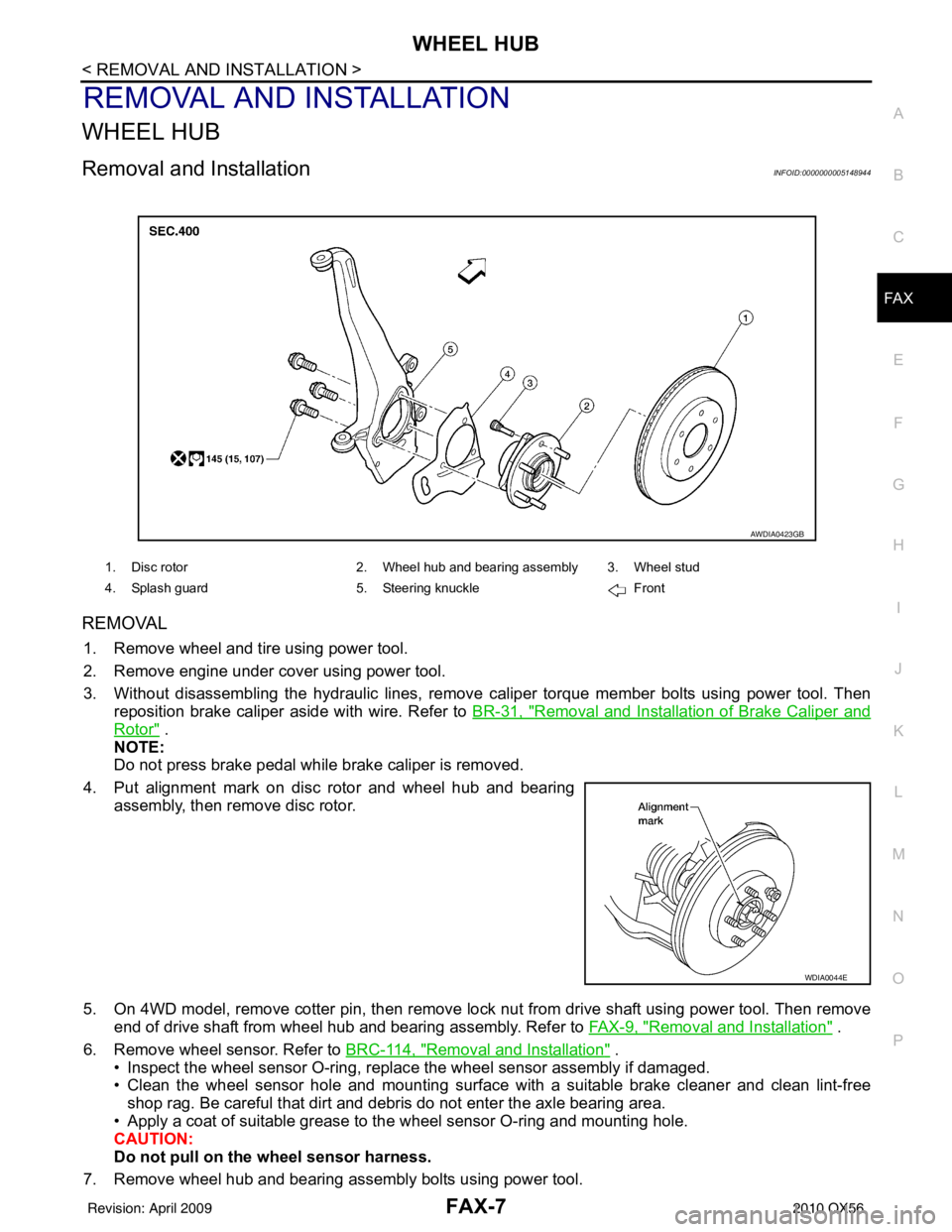
Removal and InstallationINFOID:0000000005148944
REMOVAL
1. Remove wheel and tire using power tool.
2. Remove engine under cover using power tool.
3. Without disassembling the hydraulic lines, remove caliper torque member bolts using power tool. Then
reposition brake caliper aside with wire. Refer to BR-31, "
Removal and Installation of Brake Caliper and
Rotor" .
NOTE:
Do not press brake pedal while brake caliper is removed.
4. Put alignment mark on disc rotor and wheel hub and bearing assembly, then remove disc rotor.
5. On 4WD model, remove cotter pin, then remove lock nut from drive shaft using power tool. Then remove end of drive shaft from wheel hub and bearing assembly. Refer to FAX-9, "
Removal and Installation" .
6. Remove wheel sensor. Refer to BRC-114, "
Removal and Installation" .
• Inspect the wheel sensor O-ring, replac e the wheel sensor assembly if damaged.
• Clean the wheel sensor hole and mounting surface with a suitable brake cleaner and clean lint-free shop rag. Be careful that dirt and debris do not enter the axle bearing area.
• Apply a coat of suitable grease to the wheel sensor O-ring and mounting hole.
CAUTION:
Do not pull on the wheel sensor harness.
7. Remove wheel hub and bearing assembly bolts using power tool.
1. Disc rotor 2. Wheel hub and bearing assembly 3. Wheel stud
4. Splash guard 5. Steering knuckle Front
AWDIA0423GB
WDIA0044E
Revision: April 20092010 QX56
Page 2174 of 4210

FAX-8
< REMOVAL AND INSTALLATION >
WHEEL HUB
8. Remove splash guard and wheel hub and bearing assembly from steering knuckle.
INSPECTION AFTER REMOVAL
Check for deformity, cracks and damage on each part, replace if necessary.
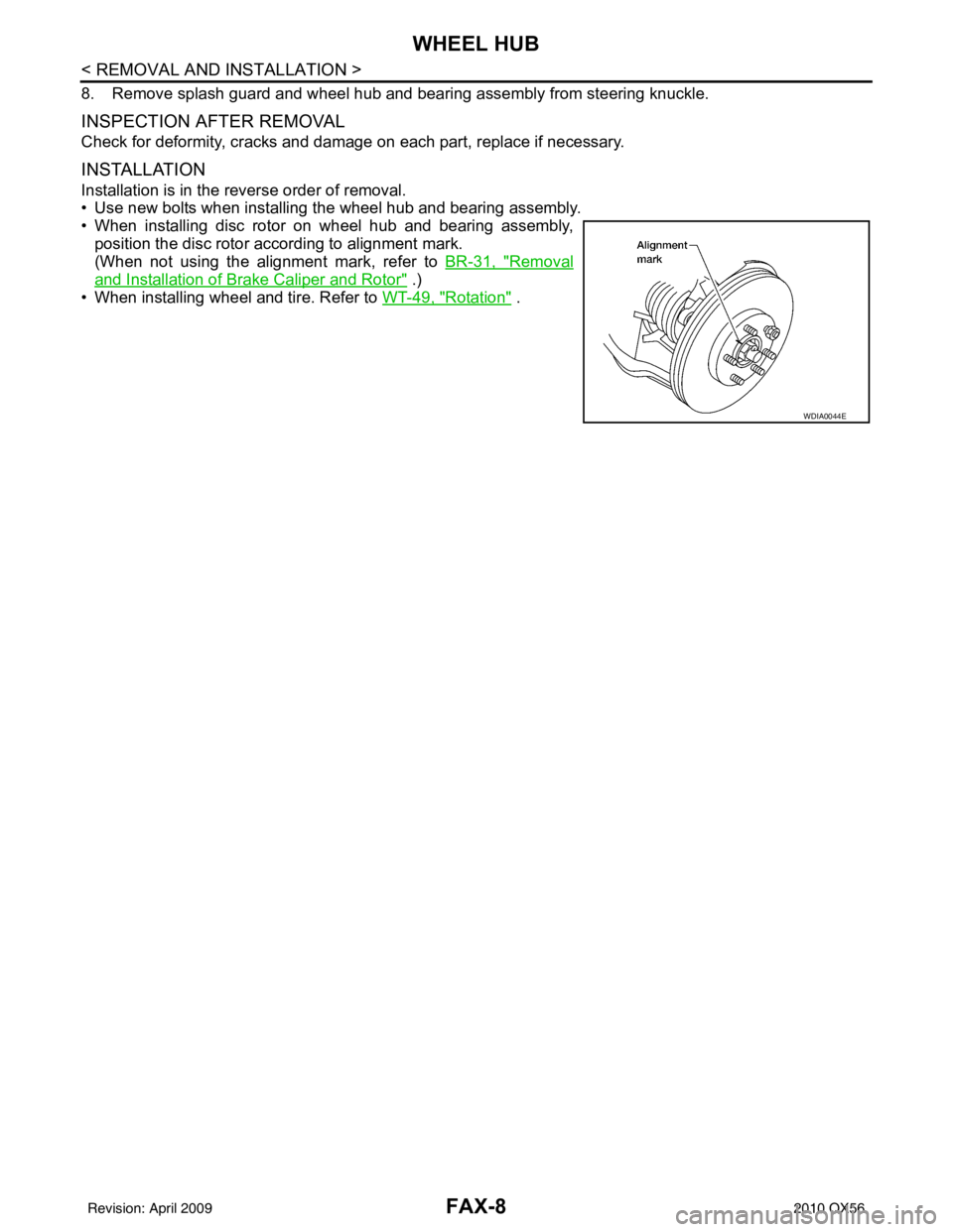
INSTALLATION
Installation is in the reverse order of removal.
• Use new bolts when installing the wheel hub and bearing assembly.
• When installing disc rotor on wheel hub and bearing assembly,
position the disc rotor according to alignment mark.
(When not using the alignment mark, refer to BR-31, "
Removal
and Installation of Brake Caliper and Rotor" .)
• When installing wheel and tire. Refer to WT-49, "
Rotation" .
WDIA0044E
Revision: April 20092010 QX56
Page 2200 of 4210

FSU-1
SUSPENSION
C
DF
G H
I
J
K L
M
SECTION FSU
A
B
FSU
N
O PCONTENTS
FRONT SUSPENSION
PRECAUTION ....... ........................................2
PRECAUTIONS .............................................. .....2
Precaution for Supplemental Restraint System
(SRS) "AIR BAG" and "SEAT BELT PRE-TEN-
SIONER" ............................................................. ......
2
Precaution Necessary for Steering Wheel Rota-
tion After Battery Disconnect ............................... ......
2
Precaution .................................................................3
PREPARATION ............................................4
PREPARATION .............................................. .....4
Special Service Tool ........................................... ......4
Commercial Service Tool ..........................................4
SYMPTOM DIAGNOSIS ...............................5
NOISE, VIBRATION AND HARSHNESS
(NVH) TROUBLESHOOTING ........................ .....
5
NVH Troubleshooting Chart ................................ ......5
ON-VEHICLE MAINTENANCE .....................6
ON-VEHICLE SERVICE ................................. .....6
Front Suspension Parts ....................................... ......6
Front Wheel Alignment ..............................................6
UPPER BALL JOINT AND LOWER BALL
JOINT .................................................................
10
Inspection ............................................................ ....10
KNUCKLE ...................................................... ....12
On-Vehicle Inspection and Service ..................... ....12
ON-VEHICLE REPAIR .................................13
FRONT SUSPENSION ASSEMBLY .............. ....13
Component .......................................................... ....13
REMOVAL AND INSTALLATION ...............14
COIL SPRING AND SHOCK ABSORBER .......14
Removal and Installation ..................................... ....14
Disposal ...................................................................14
STABILIZER BAR .............................................15
Removal and Installation .........................................15
UPPER LINK .....................................................16
Removal and Installation ..................................... ....16
LOWER LINK ....................................................17
Removal and Installation .........................................17
UPPER BALL JOINT AND LOWER BALL
JOINT ................................................................
18
Removal and Installation .........................................18
KNUCKLE .........................................................19
Removal and Installation ..................................... ....19
DISASSEMBLY AND ASSEMBLY ..............21
COIL SPRING AND SHOCK ABSORBER .......21
Disassembly and Assembly ................................. ....21
SERVICE DATA AND SPECIFICATIONS
(SDS) ............... .......................................... ...
23
SERVICE DATA AND SPECIFICATIONS
(SDS) .................................................................
23
General Specification .......................................... ....23
Spring Free Height ..................................................23
Wheel Alignment (Unladen*1) ..................................23
Ball Joint .............................................................. ....24
Wheelarch Height (Unladen*1) ................................24
Revision: April 20092010 QX56
Page 2202 of 4210

PRECAUTIONSFSU-3
< PRECAUTION >
C
DF
G H
I
J
K L
M A
B
FSU
N
O P
5. When the repair work is completed, return the ignition switch to the ″LOCK ″ position before connecting
the battery cables. (At this time, the steering lock mechanism will engage.)
6. Perform a self-diagnosis check of al l control units using CONSULT-III.
PrecautionINFOID:0000000005148104
• When installing the rubber bushings, the final tightening must be done under unladen condition and with the
tires on level ground. Oil will shorten the life of the rubber bushings, so wipe off any spilled oil immediately.
• Unladen condition means the fuel tank, engine coolant and lubricants are at the full specification. The spare
tire, jack, hand tools, and mats are in their designated positions.
• After installing suspension components, check the wheel alignment.
• Lock nuts are not reusable. Always use new lock nuts for installation. New lock nuts are pre-oiled, do not
apply any additional lubrication.
Revision: April 20092010 QX56
Page 2203 of 4210

FSU-4
< PREPARATION >
PREPARATION
PREPARATION
PREPARATION
Special Service ToolINFOID:0000000005148105
The actual shapes of Kent-Moore tools may differ from those of special service tools illustrated here.
Commercial Service ToolINFOID:0000000005148106
Tool number
(Kent-Moore No.)
Tool name Description
ST29020001
(J-24319-01)
Pitman arm puller Removing upper link ball joint from knuckle
spindle
a: 34 mm (1.34 in)
b: 6.5 mm (0.256 in)
c: 61.5 mm (2.421 in)
HT72520000
(J-25730-A)
Ball joint remover Removing tie-rod outer end
NT694
NT146
Tool name
Description
Attachment wheel alignment Measure wheel alignment
a: Screw M24 x 1.5 pitch
b: 35 mm (1.38 in) dia.
c: 65 mm (2.56 in) dia.
d: 56 mm (2.20 in)
e: 12 mm (0.47 in)
Spring compressor Removing and installing coil spring
Power tool Loosening bolts and nuts
NT148
NT717
PBIC0190E
Revision: April 20092010 QX56
Page 2204 of 4210

NOISE, VIBRATION AND HARSHNESS (NVH) TROUBLESHOOTINGFSU-5
< SYMPTOM DIAGNOSIS >
C
DF
G H
I
J
K L
M A
B
FSU
N
O P
SYMPTOM DIAGNOSIS
NOISE, VIBRATION AND HARSHN ESS (NVH) TROUBLESHOOTING
NVH Troubleshooting ChartINFOID:0000000005148107
Use the chart below to help you find the cause of the symptom. Repair or replace parts as necessary.
x: ApplicableReference page
FSU-13FSU-14FSU-13FSU-13FSU-24FSU-6FSU-6FSU-6
DLN-184, "
NVH Troubleshooting Chart
"
DLN-208, "
NVH Troubleshooting Chart
"
FAX-5, "
NVH Troubleshooting Chart
"
FAX-5, "
NVH Troubleshooting Chart
"
WT-43, "
NVH Troubleshooting Chart
"
WT-43, "
NVH Troubleshooting Chart
"
BR-6, "
NVH Troubleshooting Chart
"
ST-12, "
NVH Troubleshooting Chart
"
Possible Cause and
SUSPECTED PARTS
Improper installation, looseness
Shock absorber deformation,
damage or deflection
Bushing or mounting deterioration
Parts interference
Spring fatigue
Suspension looseness
Incorrect wheel alignment
Stabilizer bar fatigue
PROPELLER SHAFT
FRONT FINAL DRIVE
DRIVE SHAFT
WHEEL HUB
TIRES
ROAD WHEEL
BRAKES
STEERING
Symptom
Noise
× × ×××× × × ×× × × ××
Shake × × ×× × × ×× × × ××
Vibration × × ××× × ×× × ×
Shimmy × × ×× × × × × ××
Shudder ××× ×××××
Poor quality ride or handling × × ××× ×× × × ×
Revision: April 20092010 QX56