catalog INFINITI QX56 2011 Factory Service Manual
[x] Cancel search | Manufacturer: INFINITI, Model Year: 2011, Model line: QX56, Model: INFINITI QX56 2011Pages: 5598, PDF Size: 94.53 MB
Page 2661 of 5598

ENGINE ASSEMBLYEM-99
< UNIT REMOVAL AND INSTALLATION >
C
DE
F
G H
I
J
K L
M A
EM
NP
O
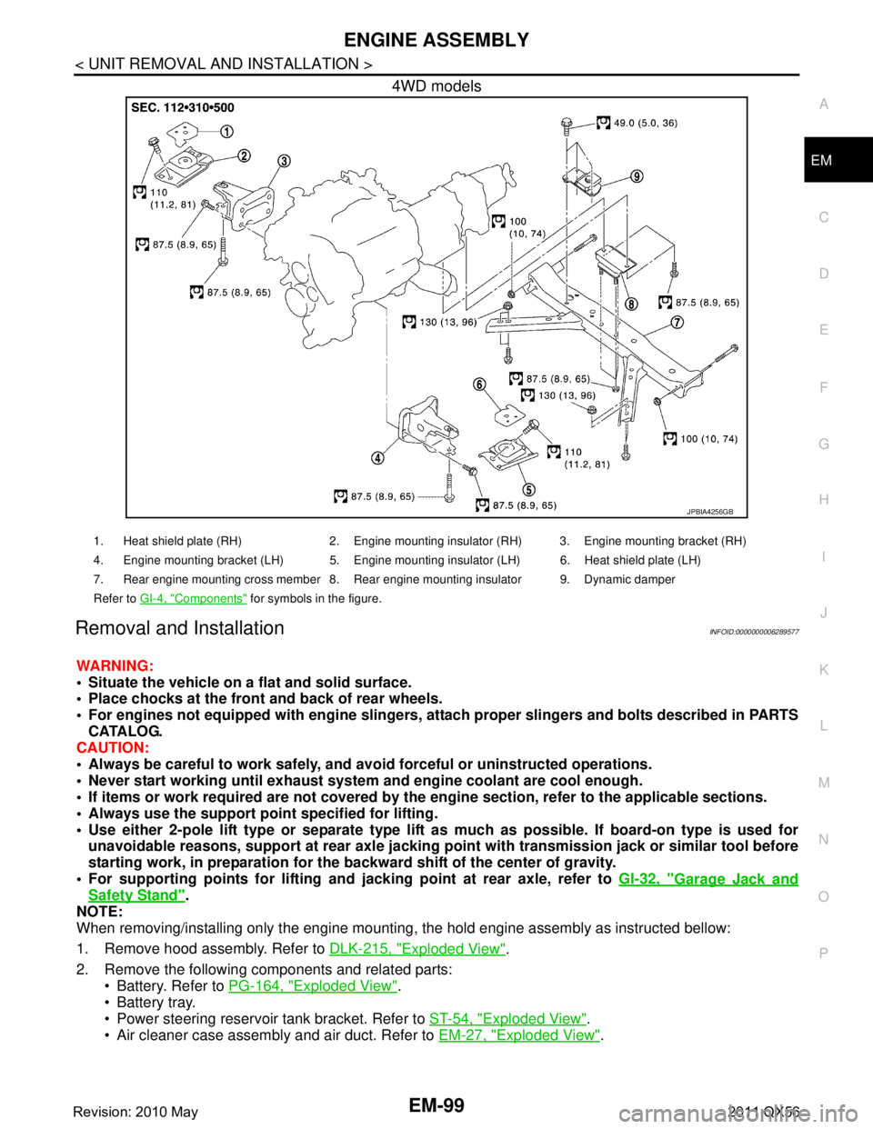
4WD models
Removal and InstallationINFOID:0000000006289577
WARNING:
Situate the vehicle on a flat and solid surface.
Place chocks at the front
and back of rear wheels.
For engines not equipped with engi ne slingers, attach proper slingers and bolts described in PARTS
CATALOG.
CAUTION:
Always be careful to work safely, and avo id forceful or uninstructed operations.
Never start working until exhaust system and engine coolant are cool enough.
If items or work required are not covered by th e engine section, refer to the applicable sections.
Always use the support poin t specified for lifting.
Use either 2-pole lift type or separate type lift as much as possible. If board-on type is used for
unavoidable reasons, support at r ear axle jacking point with transmi ssion jack or similar tool before
starting work, in preparat ion for the backward shift of the center of gravity.
For supporting points fo r lifting and jacking point at rear axle, refer to GI-32, "
Garage Jack and
Safety Stand".
NOTE:
When removing/installing only the engine mounting, the hold engine assembly as instructed bellow:
1. Remove hood assembly. Refer to DLK-215, "
Exploded View".
2. Remove the following components and related parts: Battery. Refer to PG-164, "
Exploded View".
Battery tray.
Power steering reservoir tank bracket. Refer to ST-54, "
Exploded View".
Air cleaner case assembly and air duct. Refer to EM-27, "
Exploded View".
JPBIA4256GB
1. Heat shield plate (RH) 2. Engine mounting insulator (RH) 3. Engine mounting bracket (RH)
4. Engine mounting bracket (LH) 5. Engine mounting insulator (LH) 6. Heat shield plate (LH)
7. Rear engine mounting cross member 8. Rear engine mounting insulator 9. Dynamic damper
Refer to GI-4, "
Components" for symbols in the figure.
Revision: 2010 May2011 QX56
Page 2968 of 5598

GI-4
< HOW TO USE THIS MANUAL >
HOW TO USE THIS MANUAL
Relation between Illustrations and Descriptions
INFOID:0000000006280839
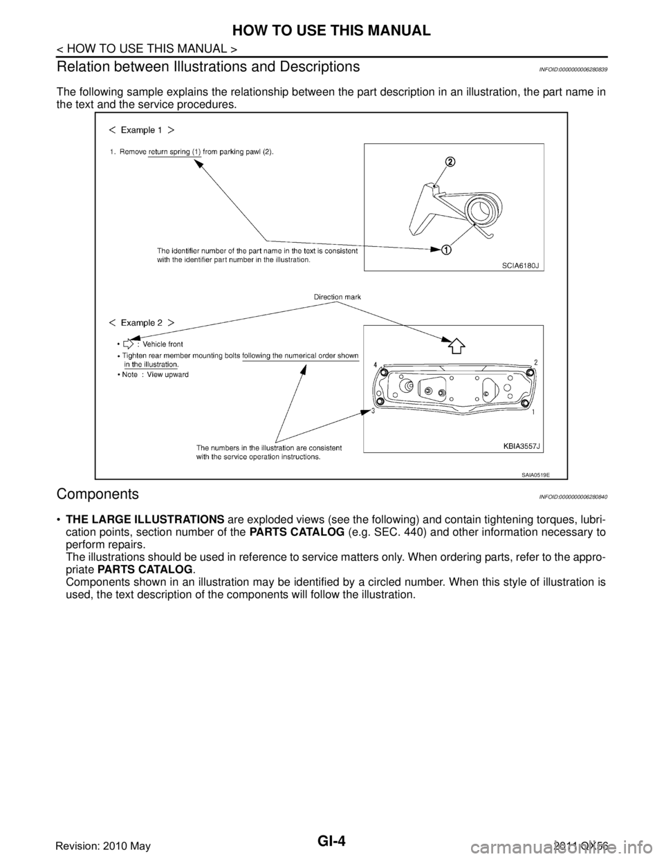
The following sample explains the relationship between t he part description in an illustration, the part name in
the text and the service procedures.
ComponentsINFOID:0000000006280840
THE LARGE ILLUSTRATIONS are exploded views (see the following) and contain tightening torques, lubri-
cation points, section number of the PARTS CATALOG (e.g. SEC. 440) and other information necessary to
perform repairs.
The illustrations should be used in reference to service matters only. When ordering parts, refer to the appro-
priate PARTS CATALOG .
Components shown in an illustration may be identified by a circled number. When this style of illustration is
used, the text description of the components will follow the illustration.
SAIA0519E
Revision: 2010 May2011 QX56