diagram INFINITI QX56 2011 Factory Service Manual
[x] Cancel search | Manufacturer: INFINITI, Model Year: 2011, Model line: QX56, Model: INFINITI QX56 2011Pages: 5598, PDF Size: 94.53 MB
Page 10 of 5598

ADP-1
BODY INTERIOR
C
DE
F
G H
I
K L
M
SECTION ADP
A
B
ADP
N
O P
CONTENTS
AUTOMATIC DRIVE POSITIONER
PRECAUTION ................ ...............................5
PRECAUTIONS .............................................. .....5
Precaution for Supplemental Restraint System
(SRS) "AIR BAG" and "SEAT BELT PRE-TEN-
SIONER" ............................................................. ......
5
SYSTEM DESCRIPTION ..............................6
COMPONENT PARTS ................................... .....6
Component Parts Location .................................. ......6
Component Description ............................................7
SYSTEM .............................................................11
AUTOMATIC DRIVE POSITIONER SYSTEM ....... ....11
AUTOMATIC DRIVE POSITIONER SYSTEM :
System Diagram ......................................................
11
AUTOMATIC DRIVE POSITIONER SYSTEM :
System Description .................................................
11
MANUAL FUNCTION ............................................ ....12
MANUAL FUNCTION : System Diagram ................13
MANUAL FUNCTION : System Description ............13
MEMORY FUNCTION ........................................... ....14
MEMORY FUNCTION : System Diagram ...............15
MEMORY FUNCTION : System Description ..........15
EXIT ASSIST FUNCTION ...................................... ....17
EXIT ASSIST FUNCTION : System Diagram .........17
EXIT ASSIST FUNCTION : Sy stem Description .....17
ENTRY ASSIST FUNCTION ................................. ....18
ENTRY ASSIST FUNCTION : System Diagram .....18
ENTRY ASSIST FUNCTION : System Description
....
18
INTELLIGENT KEY INTERLOCK FUNCTION ...... ....19
INTELLIGENT KEY INTERLOCK FUNCTION :
System Diagram ......................................................
20
INTELLIGENT KEY INTERLOCK FUNCTION :
System Description .................................................
20
Fail Safe .............................................................. ....21
DIAGNOSIS SYSTEM (DRIVER SEAT CON-
TROL UNIT) ......................................................
22
CONSULT-III Function ............................................22
ECU DIAGNOSIS INFORMATION ..............25
DRIVER SEAT CONTROL UNIT ......................25
Reference Value .................................................. ....25
Fail Safe ..................................................................30
DTC Index ...............................................................31
AUTOMATIC DRIVE POSITIONER CON-
TROL UNIT ........................................................
32
Reference Value ......................................................32
BCM (BODY CONTROL MODULE) .................35
List of ECU Reference .............................................35
WIRING DIAGRAM ......................................36
AUTOMATIC DRIVE POSITIONER SYSTEM ...36
Wiring Diagram .................................................... ....36
BASIC INSPECTION ...................................48
DIAGNOSIS AND REPAIR WORK FLOW .......48
Work Flow ............................................................ ....48
INSPECTION AND ADJUSTMENT ..................51
ADDITIONAL SERVICE WHEN REMOVING BAT-
TERY NEGATIVE TERMINAL ............................... ....
51
ADDITIONAL SERVICE WHEN REMOVING
BATTERY NEGATIVE TERMINAL : Description .....
51
ADDITIONAL SERVICE WHEN REMOVING
BATTERY NEGATIVE TERMINAL : Special Re-
pair Requirement .....................................................
51
ADDITIONAL SERVICE WHEN REPLACING
CONTROL UNIT .................................................... ....
51
Revision: 2010 May2011 QX56
Page 20 of 5598
SYSTEMADP-11
< SYSTEM DESCRIPTION >
C
DE
F
G H
I
K L
M A
B
ADP
N
O P
SYSTEM
AUTOMATIC DRIVE POSITIONER SYSTEM
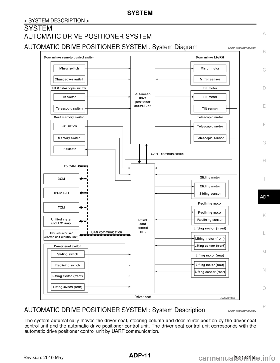
AUTOMATIC DRIVE POSITIONER SYSTEM : System DiagramINFOID:0000000006248303
AUTOMATIC DRIVE POSITIONER SYSTEM : System DescriptionINFOID:0000000006248304
The system automatically moves the driver seat, steer ing column and door mirror position by the driver seat
control unit and the automatic drive positioner control uni t. The driver seat control unit corresponds with the
automatic drive positioner control unit by UART communication.
JMJIA3773GB
Revision: 2010 May2011 QX56
Page 22 of 5598
SYSTEMADP-13
< SYSTEM DESCRIPTION >
C
DE
F
G H
I
K L
M A
B
ADP
N
O P
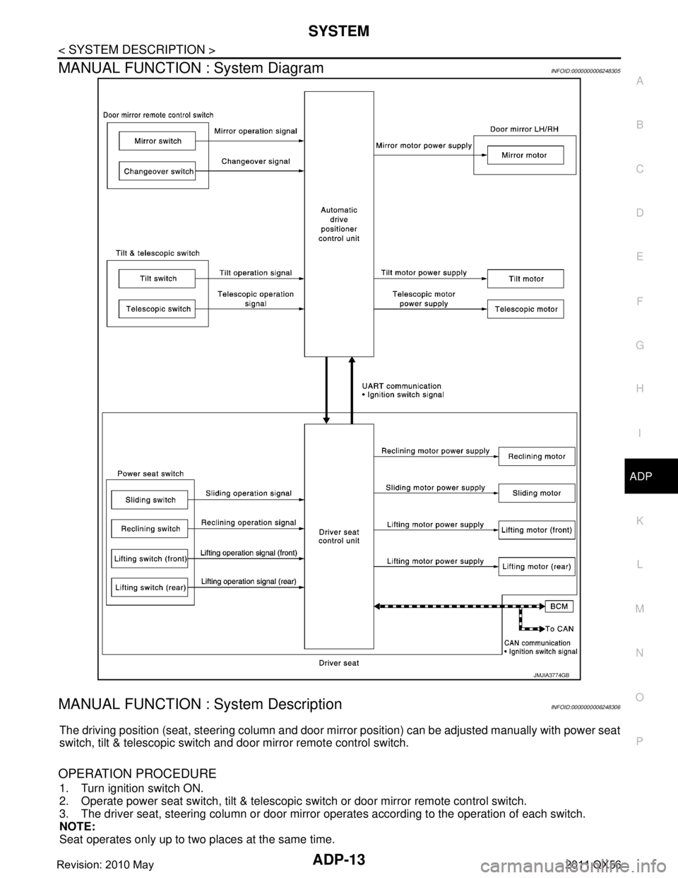
MANUAL FUNCTION : System DiagramINFOID:0000000006248305
MANUAL FUNCTION : System DescriptionINFOID:0000000006248306
The driving position (seat, steering column and door mi rror position) can be adjusted manually with power seat
switch, tilt & telescopic switch and door mirror remote control switch.
OPERATION PROCEDURE
1. Turn ignition switch ON.
2. Operate power seat switch, tilt & telescopic switch or door mirror remote control switch.
3. The driver seat, steering column or door mirror operates according to the operation of each switch.
NOTE:
Seat operates only up to two places at the same time.
JMJIA3774GB
Revision: 2010 May2011 QX56
Page 24 of 5598
SYSTEMADP-15
< SYSTEM DESCRIPTION >
C
DE
F
G H
I
K L
M A
B
ADP
N
O P
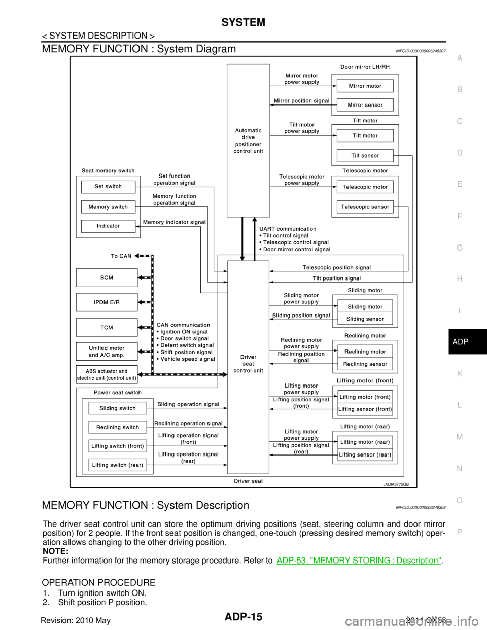
MEMORY FUNCTION : System DiagramINFOID:0000000006248307
MEMORY FUNCTION : System DescriptionINFOID:0000000006248308
The driver seat control unit can store the optimum driving positions (seat, steering column and door mirror
position) for 2 people. If the front seat position is changed, one-touch (pressing desired memory switch) oper-
ation allows changing to the other driving position.
NOTE:
Further information for the memory storage procedure. Refer to ADP-53, "
MEMORY STORING : Description".
OPERATION PROCEDURE
1. Turn ignition switch ON.
2. Shift position P position.
JMJIA3775GB
Revision: 2010 May2011 QX56
Page 26 of 5598
SYSTEMADP-17
< SYSTEM DESCRIPTION >
C
DE
F
G H
I
K L
M A
B
ADP
N
O P
EXIT ASSIST FUNCTION
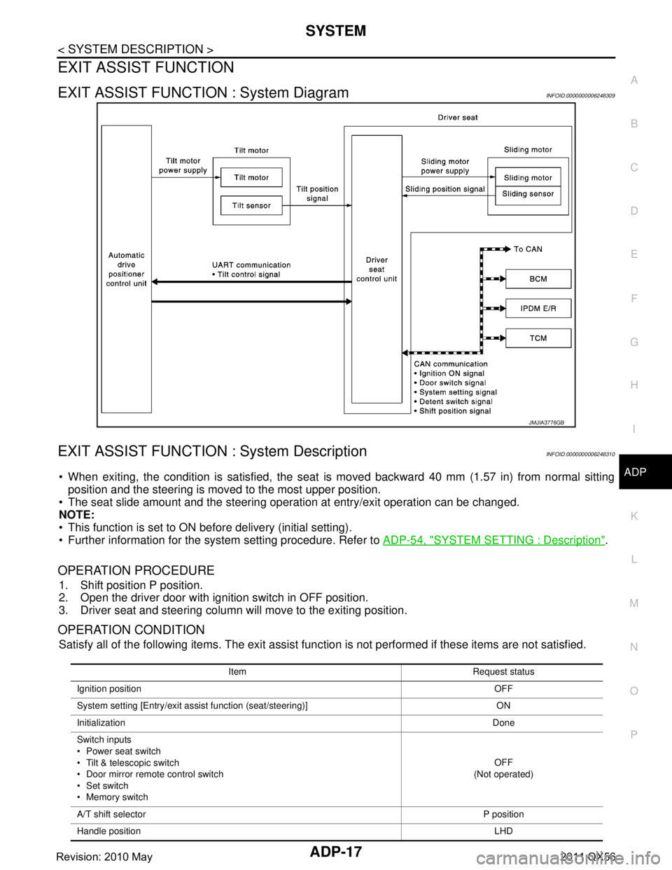
EXIT ASSIST FUNCTION : System DiagramINFOID:0000000006248309
EXIT ASSIST FUNCTION : System DescriptionINFOID:0000000006248310
When exiting, the condition is satisfied, the seat is moved backward 40 mm (1.57 in) from normal sitting
position and the steering is moved to the most upper position.
The seat slide amount and the steering oper ation at entry/exit operation can be changed.
NOTE:
This function is set to ON before delivery (initial setting).
Further information for the system setting procedure. Refer to ADP-54, "
SYSTEM SETTING : Description".
OPERATION PROCEDURE
1. Shift position P position.
2. Open the driver door with ignition switch in OFF position.
3. Driver seat and steering column will move to the exiting position.
OPERATION CONDITION
Satisfy all of the following items. The exit assist function is not performed if these items are not satisfied.
JMJIA3776GB
Item Request status
Ignition position OFF
System setting [Entry/exit assist function (seat/steering)] ON
Initialization Done
Switch inputs
Power seat switch
Tilt & telescopic switch
Door mirror remote control switch
Set switch
Memory switch OFF
(Not operated)
A/T shift selector P position
Handle position LHD
Revision: 2010 May2011 QX56
Page 27 of 5598
ADP-18
< SYSTEM DESCRIPTION >
SYSTEM
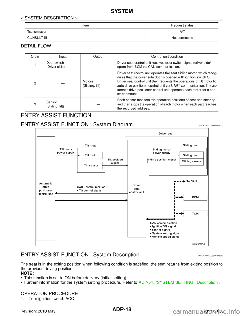
DETAIL FLOW
ENTRY ASSIST FUNCTION
ENTRY ASSIST FUNCTION : System DiagramINFOID:0000000006248311
ENTRY ASSIST FUNCTION : System DescriptionINFOID:0000000006248312
The seat is in the exiting position when following condition is satisfied, the seat returns from exiting position to
the previous driving position.
NOTE:
This function is set to ON before delivery (initial setting).
Further information for the system setting procedure. Refer to ADP-54, "
SYSTEM SETTING : Description".
OPERATION PROCEDURE
1. Turn ignition switch ACC.
Transmission A/T
CUNSULT-III Not connected
Item Request status
Order Input Output Control unit condition
1 Door switch
(Driver side)
—Driver seat control unit receives door switch signal (driver side/
open) from BCM via CAN communication.
2— Motors
(Sliding, tilt)Driver seat control unit operates the seat sliding motor, which recog-
nizes that the driver side door is opened with ignition switch OFF.
Driver seat control unit then requests the operations of tilt motor to
auto drive positioner control unit via UART communication. The au-
tomatic drive positioner control unit operates each motor for a con-
stant amount.
3 Sensor
(Sliding, tilt) —Each sensor monitors the operating positions of seat and steering,
and then stops the operation of each motor when each part reaches
the recorded address.
JMJIA3777GB
Revision: 2010 May2011 QX56
Page 29 of 5598
ADP-20
< SYSTEM DESCRIPTION >
SYSTEM
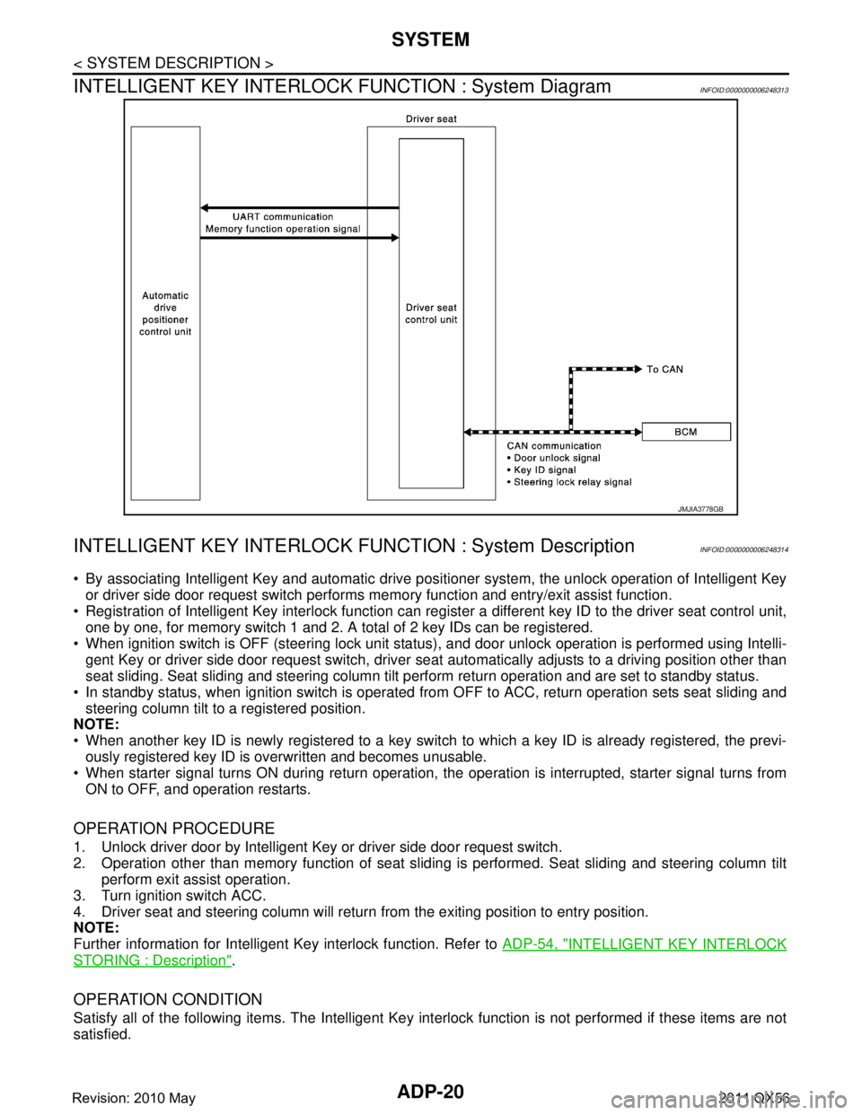
INTELLIGENT KEY INTERLOCK FUNCTION : System Diagram
INFOID:0000000006248313
INTELLIGENT KEY INTERLOCK F UNCTION : System DescriptionINFOID:0000000006248314
By associating Intelligent Key and automatic drive po sitioner system, the unlock operation of Intelligent Key
or driver side door request switch performs me mory function and entry/exit assist function.
Registration of Intelligent Key interlock function can regist er a different key ID to the driver seat control unit,
one by one, for memory switch 1 and 2. A total of 2 key IDs can be registered.
When ignition switch is OFF (steering lock unit status ), and door unlock operation is performed using Intelli-
gent Key or driver side door request swit ch, driver seat automatically adjusts to a driving position other than
seat sliding. Seat sliding and steering column tilt perform return operation and are set to standby status.
In standby status, when ignition switch is operated from OFF to ACC, return operation sets seat sliding and
steering column tilt to a registered position.
NOTE:
When another key ID is newly registered to a key switch to which a key ID is already registered, the previ-
ously registered key ID is overwritten and becomes unusable.
When starter signal turns ON during return operation, the operation is interrupted, starter signal turns from
ON to OFF, and operation restarts.
OPERATION PROCEDURE
1. Unlock driver door by Intelligent Key or driver side door request switch.
2. Operation other than memory functi on of seat sliding is performed. Seat sliding and steering column tilt
perform exit assist operation.
3. Turn ignition switch ACC.
4. Driver seat and steering column will return from the exiting position to entry position.
NOTE:
Further information for Intelligent Key interlock function. Refer to ADP-54, "
INTELLIGENT KEY INTERLOCK
STORING : Description".
OPERATION CONDITION
Satisfy all of the following items. The Intelligent Key interlock function is not performed if these items are not
satisfied.
JMJIA3778GB
Revision: 2010 May2011 QX56
Page 45 of 5598
ADP-36
< WIRING DIAGRAM >
AUTOMATIC DRIVE POSITIONER SYSTEM
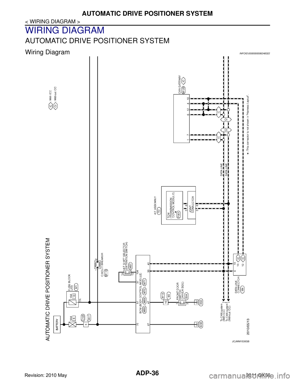
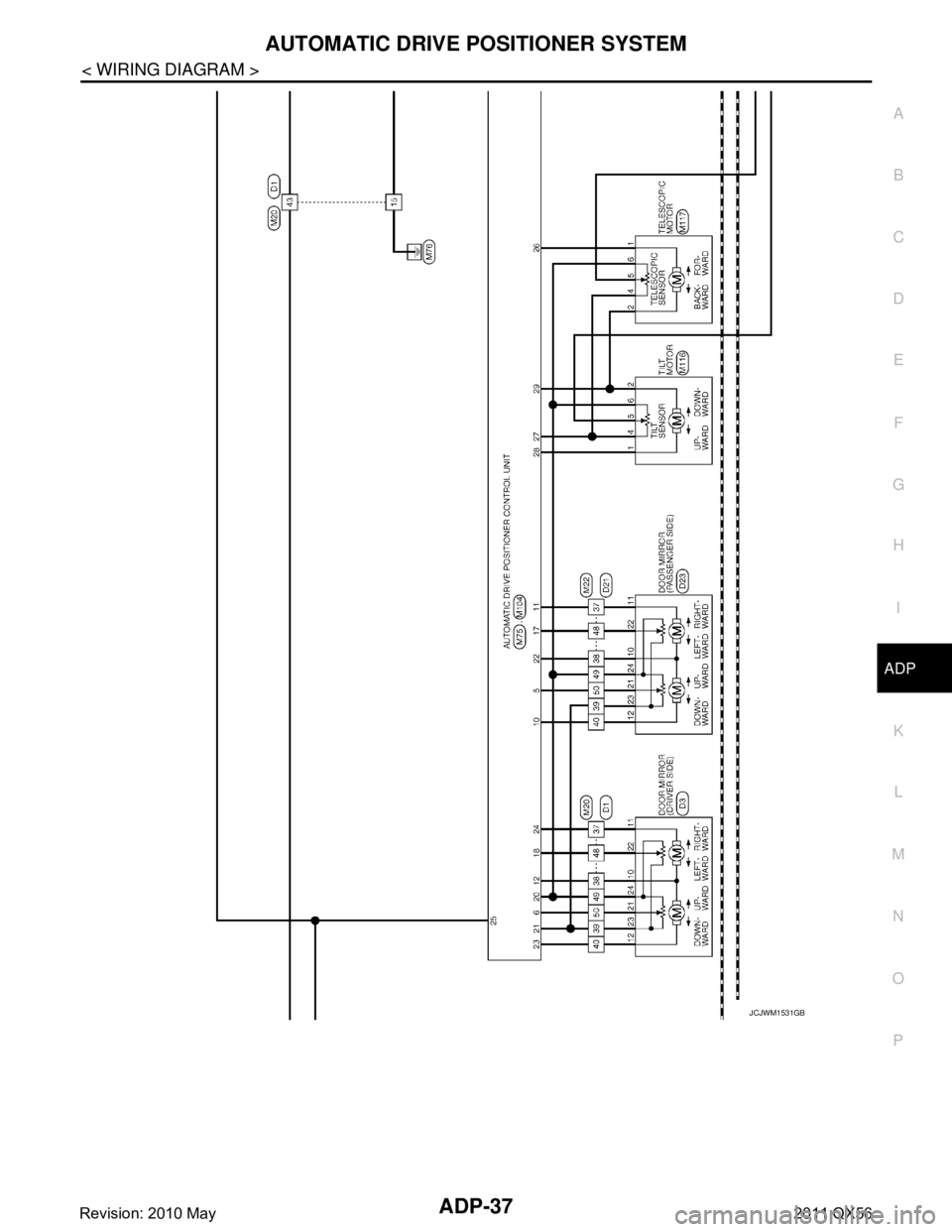
WIRING DIAGRAM
AUTOMATIC DRIVE POSITIONER SYSTEM
Wiring DiagramINFOID:0000000006248322
JCJWM1530GB
Revision: 2010 May2011 QX56
Page 46 of 5598
AUTOMATIC DRIVE POSITIONER SYSTEMADP-37
< WIRING DIAGRAM >
C
DE
F
G H
I
K L
M A
B
ADP
N
O P
JCJWM1531GB
Revision: 2010 May2011 QX56
Page 47 of 5598
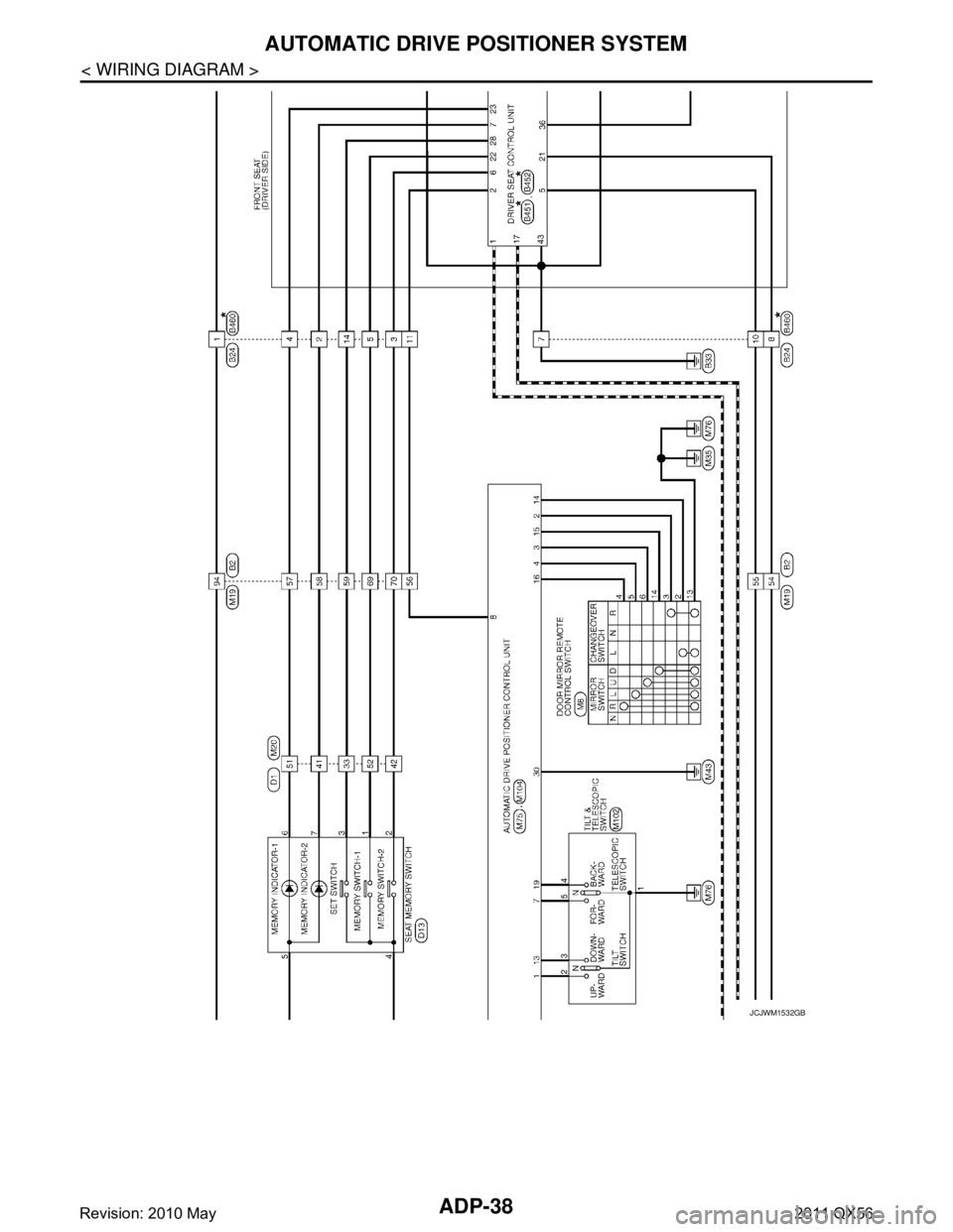
ADP-38
< WIRING DIAGRAM >
AUTOMATIC DRIVE POSITIONER SYSTEM
JCJWM1532GB
Revision: 2010 May2011 QX56