power steering INFINITI QX60 HYBRID 2016 Owner's Manual
[x] Cancel search | Manufacturer: INFINITI, Model Year: 2016, Model line: QX60 HYBRID, Model: INFINITI QX60 HYBRID 2016Pages: 651, PDF Size: 13.31 MB
Page 43 of 651

15. Power outlet (P.2-49)
16. Shift lever (P.5-17)
17. Audio system controls (P. 4-57)Front passenger air bag status light
(P. 2-13)
18. Hazard warning flasher switch (P. 6-2)
19. Push-button ignition switch (P. 5-13)
20. Cruise control main/set switches
(if so equipped) (P. 5-73)
Intelligent Cruise Control (ICC)
switches (if so equipped) (P. 5-75)
21. Dynamic Driver Assistance switch
(if so equipped) (P. 5-95)
22. Tilt steering wheel control (P. 3-29)
23. Bluetooth® Hands-Free Phone System
(P. 4-112, 4-126)
24. Steering wheel switch for audio control
(P. 4-98)
25. Hood release (P. 3-21) Vehicle Dynamic Control (VDC) OFF
switch (P. 2-47)
Heated steering wheel switch (P. 2-47)
Headlight aiming control (P. 2-38)
Warning System switch (if so
equipped) (P. 2-48)
Power inverter switch (if so equipped)
(P. 2-48) Liftgate release switch (P.3-22)
Power liftgate main switch (P. 3-22)
26. Control panel and vehicle information
display switches (P. 2-16)
*: Refer to the separate Navigation System Own-
er’s Manual (if so equipped) .
Refer to the page number indicated in pa-
rentheses for operating details.
Illustrated table of contents0-7
Page 44 of 651
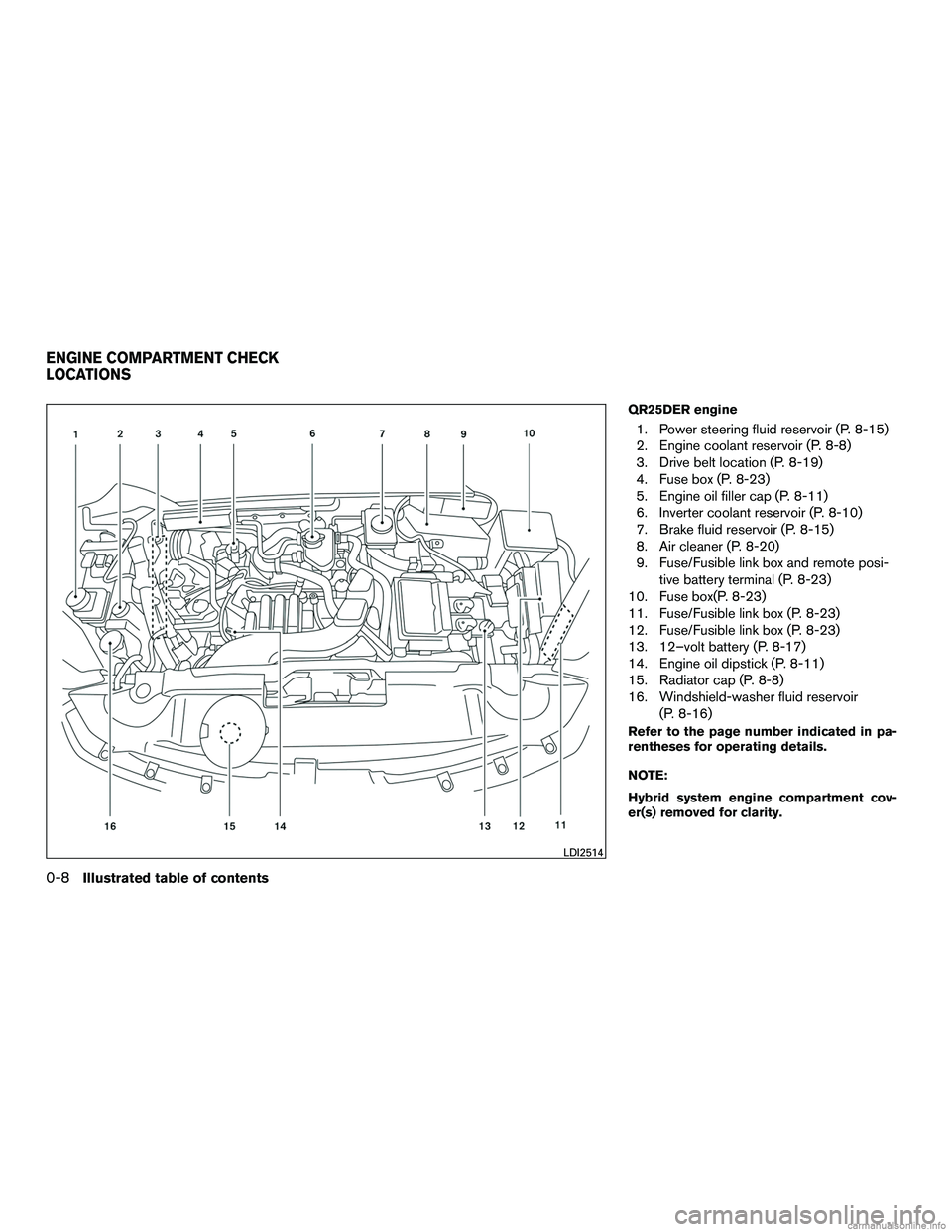
QR25DER engine
1. Power steering fluid reservoir (P. 8-15)
2. Engine coolant reservoir (P. 8-8)
3. Drive belt location (P. 8-19)
4. Fuse box (P. 8-23)
5. Engine oil filler cap (P. 8-11)
6. Inverter coolant reservoir (P. 8-10)
7. Brake fluid reservoir (P. 8-15)
8. Air cleaner (P. 8-20)
9. Fuse/Fusible link box and remote posi-tive battery terminal (P. 8-23)
10. Fuse box(P. 8-23)
11. Fuse/Fusible link box (P. 8-23)
12. Fuse/Fusible link box (P. 8-23)
13. 12–volt battery (P. 8-17)
14. Engine oil dipstick (P. 8-11)
15. Radiator cap (P. 8-8)
16. Windshield-washer fluid reservoir
(P. 8-16)
Refer to the page number indicated in pa-
rentheses for operating details.
NOTE:
Hybrid system engine compartment cov-
er(s) removed for clarity.
LDI2514
ENGINE COMPARTMENT CHECK
LOCATIONS
0-8Illustrated table of contents
Page 45 of 651

Warninglight Name Page
12–volt battery
charge warning light 2-8
or
Anti-lock Braking
System (ABS) warn-
ing light2-8
or
Brake warning light
(red)
2-8
Direct Response
Hybrid warning light2-9
Electronically con-
trolled brake warn-
ing light (yellow)2-9
Warning
light Name Page
Forward Emergency
Braking (FEB) sys-
tem warning light (if
so equipped) 2-9
Low tire pressure
warning light
2-10
Master warning light 2-11
Power steering
warning light2-11
Seat belt warning
light and chime2-12
Supplemental air
bag warning light2-12
Indicator
light Name Page
Approaching Ve-
hicle Sound for Pe-
destrians (VSP)
OFF indicator light 2-13
EV indicator light 2-13
Front fog light indi-
cator light
2-13
Front passenger air
bag status light2-13
High beam indicator
light (blue)2-13
Low temperature
indicator light (blue)2-13
Malfunction Indica-
tor Light (MIL)2-13
WARNING AND INDICATOR LIGHTS
Illustrated table of contents0-9
Page 114 of 651
2 Instruments and controls
Instrument panel...................................2-2
Meters and gauges ................................2-4
Speedometer and odometer .....................2-4
Tachometer ....................................2-5
Fuel gauge ....................................2-6
Assist Charge Gauge ...........................2-6
Warning lights, indicator lights and audible
reminders .........................................2-7
Checking lights ................................2-7
Warning lights .................................2-8
Indicator lights ................................ 2-13
Audible reminders ............................. 2-15
Vehicle Information Display ........................2-16
How to use the vehicle information display .......2-16
Startup display ................................ 2-17
Resetting the trip computer .....................2-17
Settings ...................................... 2-17
Vehicle information display warnings and
indicators ..................................... 2-27
Security systems ................................. 2-32
Vehicle security system ......................... 2-32
INFINITI vehicle immobilizer system ..............2-34
Wiper and washer switch ......................... 2-35Switch operation
.............................. 2-35
Rain-sensing auto wiper system
(if so equipped) ............................... 2-36
Rear switch operation .......................... 2-37
Rear window and outside mirror defroster switch .....2-38
Headlight and turn signal switch ....................2-38
Xenon headlights .............................. 2-38
Headlight control switch ........................ 2-39
Daytime running light system ....................2-41
Instrument brightness control ...................2-42
Turn signal switch ............................. 2-42
Fog light switch ............................... 2-43
Horn ............................................ 2-43
Heated seat switches (if so equipped) ..............2-44
Heated 2nd row seat switches (if so equipped) ......2-45
Climate controlled seat switches (if so equipped) ....2-46
Heated steering wheel
switch ...................... 2-47
Vehicle Dynamic Control (VDC) off switch ...........2-47
Warning systems switch (if so equipped) ............2-48
Power inverter switch (if so equipped) ..............2-48
E-call (SOS) switch (if so equipped) ................2-49
Power outlets .................................... 2-49
12v outlets ................................... 2-49
Page 117 of 651

15. Power outlet (P.2-49)
16. Shift lever (P.5-17)
17. Audio system controls (P. 4-57)Front passenger air bag status light
(P. 2-13)
18. Hazard warning flasher switch (P. 6-2)
19. Push-button ignition switch (P. 5-13)
20. Cruise control main/set switches
(if so equipped) (P. 5-73)
Intelligent Cruise Control (ICC)
switches (if so equipped) (P. 5-75)
21. Dynamic Driver Assistance switch
(if so equipped) (P. 5-95)
22. Tilt steering wheel control (P. 3-29)
23. Bluetooth® Hands-Free Phone System
(P. 4-112, 4-126)
24. Steering wheel switch for audio control
(P. 4-98)
25. Hood release (P. 3-21) Vehicle Dynamic Control (VDC) OFF
switch (P. 2-47)
Heated steering wheel switch (P. 2-47)
Headlight aiming control (P. 2-38)
Warning System switch
(if so equipped) (P. 2-48)
Power inverter switch (if so equipped)
(P. 2-48) Liftgate release switch (P.3-22)
Power liftgate main switch (P. 3-22)
26. Control panel and vehicle information
display switches (P. 2-16)
*: Refer to the separate Navigation System Own-
er’s Manual (if so equipped) .
Refer to the page number indicated in pa-
rentheses for operating details.
Instruments and controls2-3
Page 121 of 651

12–volt battery charge warning lightPower steering warning lightLow temperature indicator light (blue)
orAnti-lock Braking System (ABS)
warning lightSeat belt warning light and chimeMalfunction Indicator Light (MIL)
orBrake warning light (red)Supplemental air bag warning lightREADY to drive indicator light
Direct Response Hybrid warning lightApproaching Vehicle Sound for Pedestrians
(VSP) OFF indicator lightSecurity indicator light
Electronically controlled brake warning light
(yellow)EV indicator lightSide light and headlight indicator light (green)
Forward Emergency Braking (FEB) system
warning light (if so equipped)Front fog light indicator lightSlip indicator light
Low tire pressure warning lightFront passenger air bag status lightTurn signal/hazard indicator lights
Master warning lightHigh beam indicator light (blue)Vehicle Dynamic Control (VDC) OFF indicator
light
CHECKING LIGHTS
With all doors closed, apply the parking brake,
fasten the seat belts and place the ignition switchin the ON position without starting the engine.
The following lights (if so equipped) will come on:
,or(red) ,,
The following lights (if so equipped) come on
briefly and then go off:
or,,,,
WARNING LIGHTS, INDICATOR
LIGHTS AND AUDIBLE REMINDERS
Instruments and controls2-7
Page 125 of 651

●If the light illuminates while driving,
avoid sudden steering maneuvers or
abrupt braking, reduce vehicle speed,
pull off the road to a safe location and
stop the vehicle as soon as possible.
Driving with under-inflated tires may
permanently damage the tires and in-
crease the likelihood of tire failure. Se-
rious vehicle damage could occur and
may lead to an accident and could result
in serious personal injury or death.
Check the tire pressure for all four tires.
Adjust the tire pressure to the recom-
mended COLD tire pressure shown on
the tire placard label located in the driv-
er’s door opening to turn the low tire
pressure warning light OFF. If the light
still illuminates while driving after ad-
justing the tire pressure, a tire may be
flat. If you have a flat tire, replace it with
a spare tire as soon as possible. ●
Since the spare tire is not equipped with
the TPMS, when a spare tire is mounted
or a wheel is replaced tire pressure will
not be indicated, the TPMS will not
function and the low tire pressure warn-
ing light will flash for approximately
1 minute. The light will remain on after
1 minute. Have your tires replaced
and/or TPMS system reset as soon as
possible. It is recommended that you
visit an INFINITI retailer for these
services.
● Replacing tires with those not originally
specified by INFINITI could affect the
proper operation of the TPMS.
CAUTION
●The TPMS is not a substitute for the
regular tire pressure check. Be sure to
check the tire pressure regularly.
● If the vehicle is being driven at speeds
of less than 16 mph (25 km/h), the
TPMS may not operate correctly.
● Be sure to install the specified size of
tires to the four wheels correctly.
Master warning light
When the ignition switch is in the ON position,
the master warning light illuminates if any of the
following are displayed on the vehicle information
display:
● No key warning
● Low fuel warning
● Low washer fluid warning
● Parking brake release warning
● Door open warning
● Loose fuel cap warning (if so equipped)
● Check tire pressure warning
For additional information, refer to “Vehicle infor-
mation display” in this section.
Power steering warning light
WARNING
● If the engine is not running or is turned
off while driving, the power assist for
the steering will not work. Steering will
be harder to operate.
Instruments and controls2-11
Page 126 of 651

●When the power steering warning light
illuminates with the engine running,
there will be no power assist for the
steering. You will still have control of
the vehicle but the steering will be
harder to operate. Have the power
steering system checked. It is recom-
mended that you visit an INFINITI re-
tailer for this service.
When the ignition switch is placed in the ON
position, the power steering warning light illumi-
nates. After starting the engine, the power steer-
ing warning light turns off. This indicates that the
electric power steering system is operational.
If the power steering warning light illuminates while
the engine is running, it may indicate the power
steering system is not functioning properly and may
need servicing. Have the hydraulic pump electric
power steering system checked. It is recommended
that you visit an INFINITI retailer for this service.
When the power steering warning light illuminates
with the engine running, there will be no power
assist for the steering but you will still have control
of the vehicle. At this time, greater steering effort is
required to operate the steering wheel, especially
in sharp turns and at low speeds.
For additional information, refer to “Power steering”
in the “Starting and driving” section of this manual.
Seat belt warning light and chime
The light and chime remind you to fasten your
seat belts. The light illuminates whenever the
ignition switch is placed in the ON or START
position and remains illuminated until the driver’s
seat belt is fastened. At the same time, the chime
sounds for about 6 seconds unless the driver’s
seat belt is securely fastened.
The seat belt warning light may also illuminate if
the front passenger’s seat belt is not fastened
when the front passenger’s seat is occupied . For
7 seconds after the ignition switch is placed in
the ON position, the system does not activate the
warning light for the front passenger.
For additional information, refer to “Seat belts” in
the “Safety—Seats, seat belts and supplemental
restraint system” section for precautions on seat
belt usage.
Supplemental air bag warninglight
When the ignition switch is placed in the ON
position, the supplemental air bag warning light
illuminates for about 7 seconds and then turns
off. This means the system is operational. If any of the following conditions occur, the front
air bag, front seat-mounted side-impact air bag,
roof-mounted curtain air bag and pretensioner
systems need servicing:
● The supplemental air bag warning light re-
mains on after approximately 7 seconds.
● The supplemental air bag warning light
flashes intermittently.
● The supplemental air bag warning light does
not come on at all.
It is recommended you visit an INFINITI retailer for
these services. Unless checked and repaired, the
supplemental restraint system (air bag system)
and/or the pretensioner systems may not func-
tion properly. For additional information, refer to
“Supplemental Restraint System (SRS)” in the
“Safety—Seats, seat belts and supplemental re-
straint system” section of this manual.
WARNING
If the supplemental air bag warning light
is on, it could mean that the front air bag,
side air bag, curtain air bag systems
and/or pretensioner systems will not op-
erate in an accident. To help avoid injury to
yourself or others, have your vehicle
checked. It is recommended you visit an
INFINITI retailer for this service.
2-12Instruments and controls
Page 161 of 651

The heated steering wheel system is designed to
operate only when the surface temperature of the
steering wheel is below 68°F (20°C) .
Push the heated steering wheel switch to warm
the steering wheel after the engine starts. The
indicator light will come on.
If the surface temperature of the steering wheel is
below 68°F (20°C) , the system will heat the
steering wheel and cycle off and on to maintain a
temperature above 68°F (20°C) . The indicator
light will remain on as long as the system is on.
Push the switch again to turn the heated steering
wheel system off manually. The indicator light will
go off.NOTE:
If the surface temperature of the steering
wheel is above 68°F (20°C) when the switch
is turned on, the system will not heat the
steering wheel. This is not a malfunction.
The vehicle should be driven with the VDC sys-
tem on for most driving conditions.
If the vehicle is stuck in mud or snow, the VDC
system reduces the engine output to reduce
wheel spin. The engine speed will be reduced
even if the accelerator is depressed to the floor. If
maximum engine power is needed to free a stuck
vehicle, turn the VDC system off.
To turn off the VDC system, push the VDC OFF
switch. The
indicator will come on.
Push the VDC OFF switch again or restart the
engine to turn on the system. For additional infor-
mation, refer to “Vehicle Dynamic Control (VDC)
system” in the “Starting and driving” section of
this manual.
LIC0421LIC3344
HEATED STEERING WHEEL SWITCH VEHICLE DYNAMIC CONTROL (VDC)
OFF SWITCH
Instruments and controls2-47
Page 187 of 651
3 Pre-driving checks and adjustments
Keys .............................................3-2INFINITI Intelligent Key ..........................3-2
INFINITI Vehicle Immobilizer System keys ..........3-4
Doors ............................................3-4
Locking with key ................................3-5
Locking with inside lock knob ....................3-5
Locking with power door lock switch . . . ..........3-6
Automatic door locks ...........................3-6
Child safety rear door lock .......................3-6
INFINITI Intelligent Key System ......................3-7
Operating range ................................3-8
Door locks/unlocks precaution ...................3-9
INFINITI Intelligent Key Operation ...............3-10
How to use the remote keyless entry
function ...................................... 3-13
Warning signals ............................... 3-16
Troubleshooting guide ......................... 3-17
Remote Engine Start (if so equipped) ...............3-19
Remote engine start operating range . . . .........3-19
Remote starting the vehicle .....................3-19
Extending engine run time ......................3-20
Canceling a remote start .......................3-20Conditions the remote start will not work
.........3-20
Hood ........................................... 3-21
Liftgate .......................................... 3-22
Operating the power liftgate ....................3-22
Power liftgate main switch ......................3-25
Liftgate release lever ........................... 3-26
Liftgate position setting ........................ 3-26
Fuel-filler door ................................... 3-27
Opening the fuel-filler door .....................3-27
Fuel-filler cap ................................. 3-27
Steering wheel ................................... 3-29
Tilt and telescopic operation ....................3-30
Sun visors ....................................... 3-31
Vanity mirrors ................................. 3-31
Mirrors .......................................... 3-32
Automatic anti-glare rearview mirror .............3-32
Outside mirrors ............................... 3-32
Automatic drivepositioner
(if so equipped) ..........3-34
Memory storage function .......................3-34
Entry/exit function ............................. 3-35
Setting memory function ........................ 3-36
System operation .............................. 3-36