window INFINITI QX70 2014 Owner's Guide
[x] Cancel search | Manufacturer: INFINITI, Model Year: 2014, Model line: QX70, Model: INFINITI QX70 2014Pages: 530, PDF Size: 2.48 MB
Page 146 of 530

3 Pre-driving checks and adjustments
Keys .................................................................... 3-2Intelligent Key ................................................. 3-2
Valet hand-off.................................................. 3-3
Doors .................................................................. 3-4 Locking with mechanical key ........................... 3-4
Opening and closing windows with the
mechanical key................................................ 3-4
Locking with inside lock knob ......................... 3-5
Locking with power door lock switch ............... 3-5
Automatic door locks....................................... 3-5
Child safety rear door lock .............................. 3-6
Intelligent Key system ......................................... 3-6 Intelligent Key operating range ........................ 3-8
Door locks/unlocks precaution ........................ 3-9
Intelligent Key operation ................................. 3-9
Battery saver system ..................................... 3-12
Warning signals............................................. 3-12
Troubleshooting guide ................................... 3-13
Remote keyless entry system............................. 3-14 How to use remote keyless entry system....... 3-14
Hood ................................................................. 3-18 Lift gate ............................................................ 3-18
Operating power lift gate ............................. 3-19
Auto closure ................................................ 3-23
Lift gate release lever .................................. 3-24
Fuel-filler door................................................... 3-24 Opening the fuel-filler door.......................... 3-24
Fuel-filler cap............................................... 3-24
Tilt/telescopic steering ...................................... 3-27 Manual operation (if so equipped) ............... 3-27
Electric operation (if so equipped) ............... 3-27
Sun visors......................................................... 3-28
Mirrors .............................................................. 3-29 Inside mirror................................................ 3-29
Outside mirrors............................................ 3-30
Vanity mirror................................................ 3-32
Automatic drive positioner (if so equipped) ....... 3-32
Entry/exit function ....................................... 3-32
Seat synchronization function ...................... 3-33
Memory storage........................................... 3-34
System operation......................................... 3-35
Page 149 of 530

3-4Pre-driving checks and adjustments
WARNING
.Always have the doors locked while
driving. Along with the use of seat belts,
this provides greater safety in the event
of an accident by helping to prevent
persons from being thrown from the
vehicle. This also helps keep children
and others from unintentionally opening
the doors, and will help keep out
intruders.
. Before opening any door, always look for
and avoid oncoming traffic.
. Do not leave children unattended inside
the vehicle. They could unknowingly
activate switches or controls. Unat-
tended children could become involved
in serious accidents.
SPA2457B
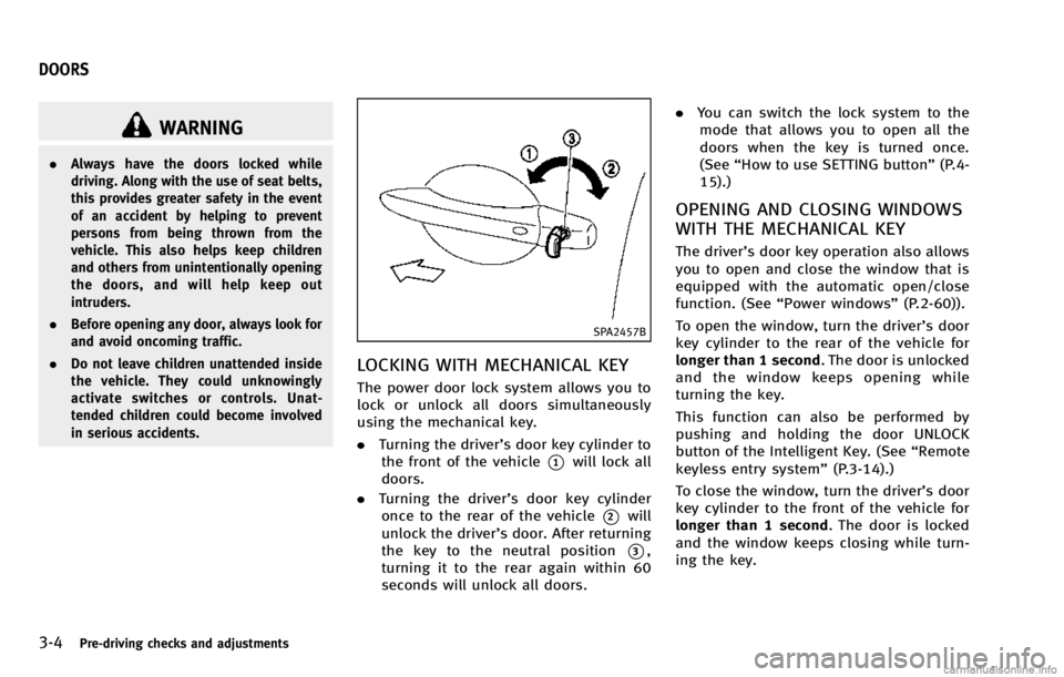
LOCKING WITH MECHANICAL KEY
The power door lock system allows you to
lock or unlock all doors simultaneously
using the mechanical key.
.Turning the driver’s door key cylinder to
the front of the vehicle
*1will lock all
doors.
. Turning the driver’s door key cylinder
once to the rear of the vehicle
*2will
unlock the driver’s door. After returning
the key to the neutral position
*3,
turning it to the rear again within 60
seconds will unlock all doors. .
You can switch the lock system to the
mode that allows you to open all the
doors when the key is turned once.
(See “How to use SETTING button” (P.4-
15).)
OPENING AND CLOSING WINDOWS
WITH THE MECHANICAL KEY
The driver’s door key operation also allows
you to open and close the window that is
equipped with the automatic open/close
function. (See “Power windows” (P.2-60)).
To open the window, turn the driver’s door
key cylinder to the rear of the vehicle for
longer than 1 second. The door is unlocked
and the window keeps opening while
turning the key.
This function can also be performed by
pushing and holding the door UNLOCK
button of the Intelligent Key. (See “Remote
keyless entry system” (P.3-14).)
To close the window, turn the driver’s door
key cylinder to the front of the vehicle for
longer than 1 second. The door is locked
and the window keeps closing while turn-
ing the key.
DOORS
Page 159 of 530

3-14Pre-driving checks and adjustments
WARNING
The Intelligent Key transmits radio waves
when the buttons are pushed. The FAA
advises that radio waves may affect aircraft
navigation and communication systems. Do
not operate the Intelligent Key while on an
airplane. Make sure the buttons are not
operated unintentionally when the unit is
stored for a flight.
It is possible to lock/unlock all doors, the
lift gate, fuel-filler door, activate the panic
alarm and open the windows by pushing
the buttons on the Intelligent Key from
outside the vehicle.
Before locking the doors, make sure the
Intelligent Key is not left in the vehicle.
The LOCK/UNLOCK button on the Intelli-
gent Key can operate at a distance of
approximately 33 ft (10 m) from the
vehicle. (The effective distance depends
upon the conditions around the vehicle.)
As many as 4 Intelligent Keys can be used
with one vehicle. For information concern-
ing the purchase and use of additional
Intelligent Keys, contact an INFINITI retai-
ler.The lock and unlock buttons on the
Intelligent Key will not operate when:
.
the distance between the Intelligent Key
and the vehicle is over 33 ft (10 m).
. the Intelligent Key battery runs down.
After locking with the remote keyless entry
function, pull the door handle to make sure
the doors are securely locked.
The LOCK/UNLOCK operating range varies
depending on the environment. To securely
operate the lock and unlock buttons,
approach the vehicle to about 3 ft (1 m)
from the door.SPA2436
*1LOCK button
*2UNLOCK button
*3Power lift gate button
*4PANIC button
HOW TO USE REMOTE KEYLESS
ENTRY SYSTEM
When you lock or unlock the doors or the
lift gate, the hazard indicator will flash and
the horn (or the outside chime) will sound
as a confirmation. For details, see “Setting
hazard indicator and horn mode” (P.3-16).
REMOTE KEYLESS ENTRY SYSTEM
Page 160 of 530

Locking doors and fuel-filler door
1. Move the shift lever to the P (Park)position, push the ignition switch to the
OFF position and make sure you carry
the Intelligent Key with you.*
2. Close all the doors and the lift gate.
3. Push the LOCK
button*1on the
Intelligent Key.
4. All the doors, the lift gate and fuel-filler door will lock.
5. The hazard indicator flashes twice and the horn chirps once.
*: Doors will lock with the Intelligent Key
while the ignition switch is in the ACC or
ON position.
Unlocking doors and fuel-filler door
1. Push the UNLOCKbutton*2on the
Intelligent Key once.
2. The hazard indicator flashes once. The driver’s door and fuel-filler door will
unlock.
The puddle light and the passenger
cabin illumination will illuminate and
stay on for a short period of time.
3. Push the UNLOCK
button on the
Intelligent Key again within 60 sec- onds.
4. The hazard indicator flashes once again. All the doors will unlock.
All doors will be locked automatically
unless one of the following operations is
performed within 1 minute after pushing
the UNLOCK button on the Intelligent Key
while the doors are locked. If during this 1-
minute time period, the UNLOCK button on
the Intelligent Key is pushed, all doors will
be locked automatically after another 1
minute.
. Opening any door
. Pushing the ignition switch
Opening windows (if so equipped)
The UNLOCKbutton*2operation also
allows you to open a window that is
equipped with the automatic open func-
tion. This function will not operate while
the window timer is activated or the
windows need to be initialized. (See
“Power windows” (P.2-60).)
To open the windows, push the UNLOCK
button*2on the Intelligent Key for
about 3 seconds after the door is unlocked.
To stop opening, release the UNLOCK
button. If the window open operation is stopped
on the way while pushing the UNLOCK
button, release and push the UNLOCKbutton again until the window opens
completely.
Window cannot be closed using the In-
telligent Key.
The door window can also be operated by
turning the mechanical key in a door lock.
(See
“Doors” (P.3-4).)
Opening/closing lift gate
Opening:
1. Push the power lift gate button
*3for more than 1 second.
2. The lift gate will automatically open.
The hazard indicator flashes 4 times and
the outside chime sounds for approxi-
mately 3 seconds.
Closing:
1. Push the power lift gate button
*3.
2. The lift gate will automatically close.
If the button
*3is pushed while the
lift gate is being opened or closed, the lift
gate will reverse.
The power lift gate button
*3cannot
Pre-driving checks and adjustments3-15
Page 175 of 530

3-30Pre-driving checks and adjustments
For the HomeLink®Universal Transceiver
operation, see “HomeLink®Universal
Transceiver” (P.2-67).
SPA2214
OUTSIDE MIRRORS
WARNING
Objects viewed in the outside mirror on the
passenger side are closer than they appear.
Be careful when moving to the right. Using
only this mirror could cause an accident.
Use the inside mirror or glance over your
shoulder to properly judge distances to
other objects.
Adjusting outside mirrors
The outside mirror control switch is located
at the lower part of the instrument panel.
The outside mirror will operate only when
the ignition switch is in the ACC or ON
position.
Move the switch right
*1or left*2to
select the right or left side mirror, then
adjust
*3using the control switch.
Defrosting outside mirrors
The outside mirrors will be heated when
the rear window defroster switch is oper-
ated. (See “Rear window and outside
mirror defroster switch” (P.2-37).)
Page 211 of 530

4-30Monitor, climate, audio, phone and voice recognition systems
HOW TO ADJUST SCREEN
To adjust the Display ON/OFF, Brightness,
Tint, Color, Contrast and Black Level of the
rearview monitor, push theSETTINGbutton
with the rearview monitor on, select the
“Display” key on the screen and select the
item key and adjust the level using the
INFINITI controller.
Do not adjust the Brightness, Tint, Color,
Contrast and Black Level of the rearview
monitor while the vehicle is moving. Make
sure the parking brake is firmly applied.
OPERATING TIPS
. When the shift lever is shifted to the R
(Reverse) position, the monitor screen
automatically changes to the RearView
monitor mode. However, the radio can
be heard.
. When the view is switched, the display
images on the screen may be displayed
with some delay.
. When the temperature is extremely high
or low, the screen may not clearly
display objects. This is not a malfunc-
tion.
. When strong light is directly coming on
the camera, objects may not be dis-
played clearly. This is not a malfunc- tion.
. Vertical lines may be seen in objects on
the screen. This is due to strong
reflected light from the bumper. This
is not a malfunction.
. The screen may flicker under fluores-
cent light. This is not a malfunction.
. The colors of objects on the RearView
monitor may differ somewhat from the
actual color of objects. This is not a
malfunction.
. Objects on the monitor may not be clear
in a dark environment. This is not a
malfunction.
. If dirt, rain or snow accumulates on the
camera, the RearView monitor may not
display object clearly. Clean the cam-
era.
. Do not use alcohol, benzine or thinner
to clean the camera. This will cause
discoloration. To clean the camera,
wipe with a cloth dampened with
diluted mild cleaning agent and then
wipe with a dry cloth.
. Do not damage the camera as the
monitor screen may be adversely af-
fected.
. Do not use wax on the camera window.
Wipe off any wax with a clean cloth dampened with mild detergent diluted
with water.
Page 212 of 530

When you push theCAMERAbutton or shift
the shift lever into the R (Reverse) position
while the ignition switch is in the ON
position, the Around View Monitor oper-
ates. The monitor displays various views of
the position of the vehicle.
Available views:
. Bird-Eye View
The surrounding view of the vehicle.
. Front-Side View
The view around and ahead of the front
passenger’s side wheel.
. Front View
An approximately 150-degree view of
the front of the vehicle.
. Front-Wide View
An approximately 180-degree view of
the front of the vehicle.
. RearView
An approximately 150-degree view of
the rear of the vehicle.
. Rear-Wide View
An approximately 180-degree view of
the rear of the vehicle.
The system is designed as an aid to the
driver in situations such as slot parking or
parallel parking.
SAA2148
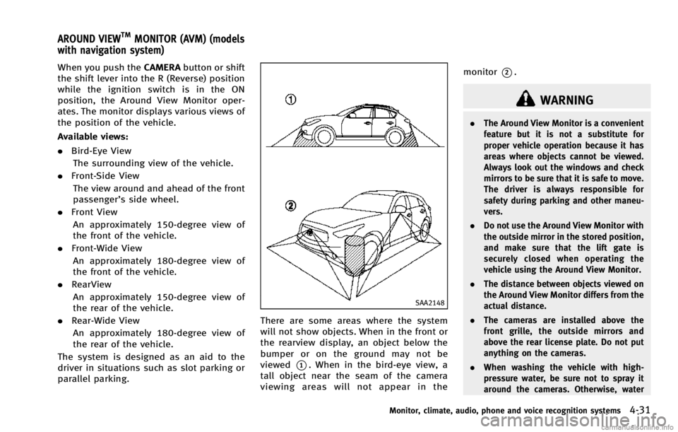
There are some areas where the system
will not show objects. When in the front or
the rearview display, an object below the
bumper or on the ground may not be
viewed
*1. When in the bird-eye view, a
tall object near the seam of the camera
viewing areas will not appear in the monitor
*2.
WARNING
.
The Around View Monitor is a convenient
feature but it is not a substitute for
proper vehicle operation because it has
areas where objects cannot be viewed.
Always look out the windows and check
mirrors to be sure that it is safe to move.
The driver is always responsible for
safety during parking and other maneu-
vers.
. Do not use the Around View Monitor with
the outside mirror in the stored position,
and make sure that the lift gate is
securely closed when operating the
vehicle using the Around View Monitor.
. The distance between objects viewed on
the Around View Monitor differs from the
actual distance.
. The cameras are installed above the
front grille, the outside mirrors and
above the rear license plate. Do not put
anything on the cameras.
. When washing the vehicle with high-
pressure water, be sure not to spray it
around the cameras. Otherwise, water
Monitor, climate, audio, phone and voice recognition systems4-31
AROUND VIEWTMMONITOR (AVM) (models
with navigation system)
Page 222 of 530

compressed-air brakes or a pneumatic
drill may affect the function of the
system; this may include reduced per-
formance or a false activation.
. This function is designed as an aid to
the driver in detecting large stationary
objects to help avoid damaging the
vehicle.
. The system is not designed to prevent
contact with small or moving objects.
. The system will not detect small objects
below the bumper, and may not detect
objects close to the bumper or on the
ground.
. The system may not detect the following
objects:
—Fluffy objects such as snow, cloth,
cotton, glass or wool.
—Thin objects such as rope, wire orchain.
—Wedge-shaped objects.
. If your vehicle sustains damage to the
bumper fascia, leaving it misaligned or
bent, the sensing zone may be altered
causing inaccurate measurement of ob-
jects or false alarms.
CAUTION
.Excessive noise (such as audio system
volume or an open vehicle window) will
interfere with the tone and it may not be
heard.
. Keep the surface of the sonar sensors
(located on the front and rear bumper
fascia) free from accumulations of snow,
ice and dirt. Do not scratch the surface of
the sonar sensors when cleaning. If the
sensors are covered, the accuracy of the
sonar function will be diminished.
The system gives the tone for front objects
when the shift lever is in the D (Drive)
position and both front and rear objects
when the shift lever is in the R (Reverse)
position.
When the camera image is shown on the
display, the system shows the sonar
indicator regardless of the shift lever
position.
The system is deactivated at speeds above
6 MPH(10 km/h). It is reactivated at lower
speeds.
When the objects are detected, the indi- cator (green) appears and blinks and the
tone sounds intermittently. When the
vehicle moves closer to the object, the
color of the indicator turns yellow and the
rate of the blinking and the rate of the tone
increase. When the vehicle is very close to
the object, the indicator stops blinking and
turns red, and the tone sounds continu-
ously.
The intermittent tone will stop after three
seconds when an object is detected by
only the corner sonar and the distance
does not change.
The tone will stop when the object gets
away from the vehicle.
Monitor, climate, audio, phone and voice recognition systems4-41
Page 225 of 530

4-44Monitor, climate, audio, phone and voice recognition systems
While the sonar is beeping, the MOD
system does not chime.
A blue MOD icon
*3is displayed in the
view where the MOD system is operative. A
gray MOD icon
*3is displayed in the view
where the MOD system is not operative.
When the “MOD”key
*4is selected, the
MOD system will turn off temporarily and
the indicator
*5will turn off. At the same
time a camera-aiding sonar will also be
turned OFF. When the “MOD” key is
selected again, the indicator will turn on
and the MOD system will turn back on.
If the MOD system is turned off, the MOD
icon
*3is not displayed.
The MOD system will turn on automatically
under the following conditions:
. When the shift lever is in the R (Reverse)
position.
. When the CAMERA button is pushed to
switch from a different screen to the
camera view on the display.
. When vehicle speed decreases below
approximately 5 MPH (8 km/h).
. When the ignition switch is placed in
the “OFF” position and then back to the
“ON” position. To set the MOD system so that it remains
off at all times, use the camera settings
menu. See
“Around view monitor settings”
(P.4-45) for more information.
WARNING
. Do not use the MOD system when
towing a trailer. The system may not
function properly.
. Excessive noise (for example, audio
system volume or open vehicle window)
will interfere with the chime sound, and
it may not be heard.
. The MOD system performance will be
limited according to environmental con-
ditions and surrounding objects such as:
—When there is low contrast between
background and the moving objects.
—When there is blinking source oflight.
—When strong light such as anothervehicle’ s headlight or sunlight is
present.
—When camera orientation is not in its usual position, such as when
mirror is folded.
—When there is dirt, water drops orsnow on the camera lens.
—When the position of the movingobjects in the display is not changed.
. The MOD system might detect some-
thing like flowing water droplets on the
camera lens, white smoke from the
muffler, moving shadows, etc.
. The MOD system may not function
properly depending on the speed, direc-
tion, distance or shape of the moving
objects.
. If your vehicle sustains damage to the
parts where the camera is installed,
leaving it misaligned or bent, the sen-
sing zone may be altered and the MOD
system may not detect objects properly.
HOW TO ADJUST THE SCREEN VIEW
To adjust the Display ON/OFF, Brightness,
Tint, Color, Contrast and Black Level of the
Around View Monitor, push the SETTING
button with the Around View Monitor on,
select the item key and adjust the level
using the INFINITI controller.
Do not adjust the Brightness, Tint, Color,
Contrast and Black Level of the Around
Page 229 of 530

4-48Monitor, climate, audio, phone and voice recognition systems
SAA2149
Center ventilators
SAA2150
Side ventilators
SAA2151
Rear ventilators
Open or close, and adjust the air flow
direction of ventilators.
: This symbol indicates that the ventilators are closed.
: This symbol indicates that the ventilators areopen.
WARNING
. The air conditioner cooling function
operates only when the engine is run-
ning.
. Do not leave children or adults who
would normally require the support of
others alone in your vehicle. Pets should
not be left alone either. On hot, sunny
days, temperatures in a closed vehicle
could quickly become high enough to
cause severe or possibly fatal injuries to
people or animals.
. Do not use the recirculation mode for
long periods as it may cause the interior
air to become stale and the windows to
fog up.
Start the engine and operate the automatic
climate control system.
When the “STATUS”button is pushed, the
automatic climate control status screen
will appear. (See “How to use STATUS
button” (P.4-9).)
VENTILATORS AUTOMATIC CLIMATE CONTROL