steering wheel INFINITI QX80 2018 User Guide
[x] Cancel search | Manufacturer: INFINITI, Model Year: 2018, Model line: QX80, Model: INFINITI QX80 2018Pages: 522, PDF Size: 2.41 MB
Page 96 of 522
JVC1128X
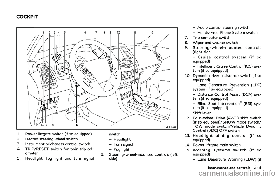
1. Power liftgate switch (if so equipped)
2. Heated steering wheel switch
3. Instrument brightness control switch
4. TRIP/RESET switch for twin trip od-ometer
5. Headlight, fog light and turn signal switch
— Headlight
— Turn signal
— Fog light
6. Steering-wheel-mounted controls (left side) — Audio control steering switch
— Hands-Free Phone System switch
7. Trip computer switch
8. Wiper and washer switch
9. Steering-wheel-mounted controls (right side)
— Cruise control system (if so
equipped)
— Intelligent Cruise Control (ICC) sys-
tem (if so equipped)
10. Dynamic driver assistance switch (if so equipped)
— Lane Departure Prevention (LDP)
system (if so equipped)
— Distance Control Assist (DCA) sys-
tem (if so equipped)
— Blind Spot Intervention
®(BSI) sys-
tem (if so equipped)
11. Shift lever
12. Four-Wheel Drive (4WD) shift switch (if so equipped)/SNOW mode switch/
TOW mode switch/Vehicle Dynamic
Control (VDC) OFF switch
13. Headlight aiming control (if so equipped)
14. Power liftgate main switch
15. Warning systems switch (if so equipped)
— Lane Departure Warning (LDW) (if
Instruments and controls2-3
COCKPIT
Page 97 of 522

2-4Instruments and controls
so equipped)
— Blind Spot Warning (BSW) (if so
equipped)
16. Electric tilting/telescopic steering wheel switch
Page 98 of 522
JVC1129X
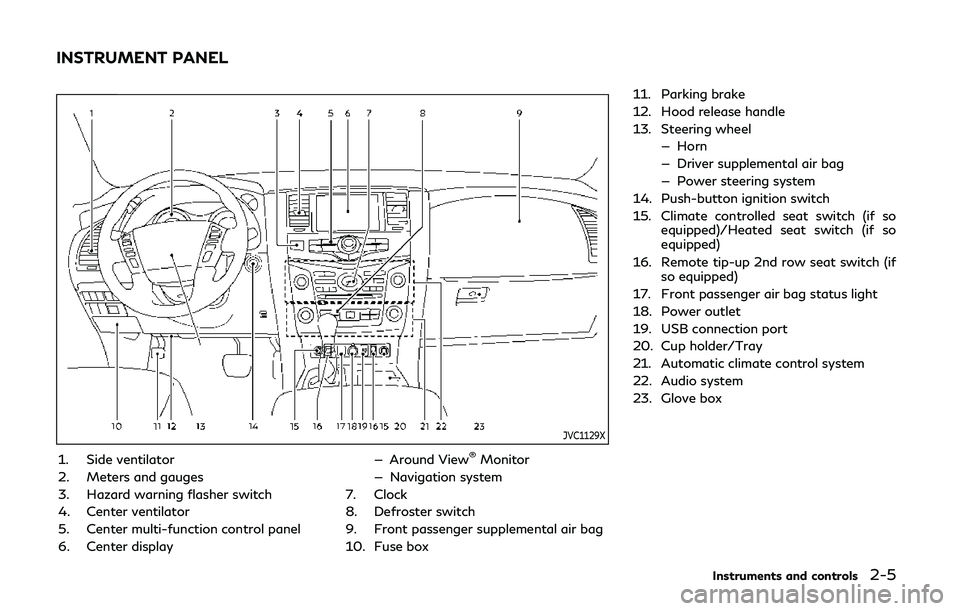
1. Side ventilator
2. Meters and gauges
3. Hazard warning flasher switch
4. Center ventilator
5. Center multi-function control panel
6. Center display— Around View®Monitor
— Navigation system
7. Clock
8. Defroster switch
9. Front passenger supplemental air bag
10. Fuse box 11. Parking brake
12. Hood release handle
13. Steering wheel
— Horn
— Driver supplemental air bag
— Power steering system
14. Push-button ignition switch
15. Climate controlled seat switch (if so equipped)/Heated seat switch (if so
equipped)
16. Remote tip-up 2nd row seat switch (if so equipped)
17. Front passenger air bag status light
18. Power outlet
19. USB connection port
20. Cup holder/Tray
21. Automatic climate control system
22. Audio system
23. Glove box
Instruments and controls2-5
INSTRUMENT PANEL
Page 109 of 522

2-16Instruments and controls
the tire pressure of all tires except the spare.
The low tire pressure warning light warns of
low tire pressure or indicates that the TPMS
is not functioning properly.
After the ignition switch is pushed ON, this
light illuminates for about 1 second and
turns off.
Low tire pressure warning:
If the vehicle is being driven with low tire
pressure, the warning light will illuminate. A
CHECK TIRE PRESSURE warning also
appears in the vehicle information display.
If you select the tire pressure information in
the center display, the Low Pressure infor-
mation will be displayed. The tire pressure
for each tire will also be displayed.
When the low tire pressure warning light
illuminates, you should stop and adjust the
tire pressure to the recommended COLD tire
pressure shown on the Tire and Loading
Information label. The low tire pressure
warning light does not automatically turn
off when the tire pressure is adjusted. After
the tire is inflated to the recommended
pressure, the vehicle must be driven at
speeds above 16 MPH (25 km/h) to activate
the TPMS and turn off the low tire pressure
warning light. Use a tire pressure gauge to
check the tire pressure.
The CHECK TIRE PRESSURE warning ap-
pears each time the ignition switch is placedin the ON position as long as the low tire
pressure warning light remains illuminated.
For additional information, see “Vehicle
information display” (P.2-21), “Tire Pressure
Monitoring System (TPMS)” (P.5-5) and
“Tire Pressure Monitoring System (TPMS) ”
(P.6-3).
TPMS malfunction:
If the TPMS is not functioning properly, the
low tire pressure warning light will flash for
approximately 1 minute when the ignition
switch is pushed ON. The light will remain on
after 1 minute. Have the system checked. It
is recommended you visit an INFINITI re-
tailer for this service. The CHECK TIRE
PRESSURE warning does not appear if the
low tire pressure warning light illuminates to
indicate a TPMS malfunction.
For additional information, see “Tire Pres-
sure Monitoring System (TPMS)” (P.5-5).
WARNING
.
If the light does not illuminate with
the ignition switch pushed ON, have
the vehicle checked as soon as possi-
ble. It is recommended you visit an
INFINITI retailer for this service.
. If the light illuminates or Low Pres-
sure information is displayed on the monitor screen while driving, avoid
sudden steering maneuvers or abrupt
braking, reduce vehicle speed, pull off
the road to a safe location and stop
the vehicle as soon as possible. Driv-
ing with under-inflated tires may
permanently damage the tires and
increase the likelihood of tire failure.
Serious vehicle damage could occur
and may lead to an accident and
could result in serious personal injury.
Check the tire pressure for all four
tires. Adjust the tire pressure to the
recommended COLD tire pressure
shown on the Tire and Loading
Information label to turn the low tire
pressure warning light OFF. If the
light still illuminates while driving
after adjusting the tire pressure, a
tire may be flat or the TPMS may be
malfunctioning. If you have a flat tire,
replace it with a spare tire as soon as
possible. If no tire is flat and all tires
are properly inflated, it is recom-
mended you consult an INFINITI
retailer.
. Since the spare tire is not equipped
with the TPMS, when a spare tire is
mounted or a wheel is replaced, the
TPMS will not function and the low
tire pressure warning light will flash
for approximately 1 minute. The light
Page 135 of 522
2-42Instruments and controls
Daytime running light system
The daytime running lights automatically
illuminate when the engine is started with
the parking brake released. The daytime
running lights operate with the headlight
switch in the OFF position or in the
position. Turn the headlight switch to theposition for full illumination when driv-
ing at night.
If the parking brake is applied before the
engine is started, the daytime running lights
do not illuminate. The daytime running lights
illuminate once the parking brake is released.
The daytime running lights will remain on
until the ignition switch is pushed to the OFF
position.
WARNING
When the daytime running light system
is active, tail lights on your vehicle are
not on. It is necessary at dusk to turn on
your headlights. Failure to do so could
cause an accident injuring yourself and
others.
Adaptive Front lighting System
(AFS) (if so equipped)
The Adaptive Front lighting System (AFS)
will automatically adjust the headlights (low
beam) toward the turning direction to
improve the driver’s view. When the head-
light switch is ON and the driver operates
the steering wheel in a turn, the AFS system
will be activated.
The AFS will operate:
. when the headlight switch is ON.
. when the shift lever is in any position
other than P (Park) or R (Reverse).
. when the vehicle is driven at above 3
MPH (5 km/h) for the left-side head-
light. Note that the right-side low beam
headlight will swivel but the left-side
headlight will not swivel when the vehicle
is below 3 MPH (5 km/h) and the
steering wheel is turned.
AFS will also adjust the headlight to a proper
axis automatically, depending on the number
of occupants in the vehicle, the load the
vehicle is carrying and the road conditions.
If the AFS OFF indicator light blinks after
the ignition switch has been pushed to the
ON position, this may indicate that the AFS
is not functioning properly. Have the system
checked. It is recommended you visit an
INFINITI retailer for this service. When the engine is started, the headlights will vibrate
to check the system condition. This is not a
malfunction.HEADLIGHT WASHER (if so
equipped)
The headlight washer operates when the
headlight is on and the ignition switch is in
the ON position.
Pull the windshield washer switch toward
you. The headlight washer operates with the
windshield washer operation. This operation
activates once each time either the ignition
switch or the headlight switch is turned off
and on.
After the first operation, the headlight
washer operates once at every fifth opera-
tion of the windshield washer.
CAUTION
.
Do not operate the washer continu-
ously for longer than 30 seconds.
. Do not operate the headlight washer
if the window washer fluid reservoir
is empty.
Page 138 of 522

JVI0395X
The heated steering wheel system is de-
signed to operate only when the surface
temperature of the steering wheel is below
68°F (20°C).
Push the heated steering wheel switch to
warm the steering wheel after the engine
starts. The indicator light
on the switch
will illuminate.
If the surface temperature of the steering
wheel is below 68°F (20°C), the system will
heat the steering wheel and cycle off and on
to maintain a temperature above 68°F
(20°C). The indicator light will remain on as
long as the system is on.
Push the switch again to turn the heated
steering wheel system off manually. The indicator light will turn off.
NOTE:
If the surface temperature of the steering
wheel is above 68°F (20°C) when the switch
is turned on, the system will not heat the
steering wheel. This is not a malfunction.
SIC4444
To sound the horn, push the center pad area
of the steering wheel.
WARNING
Do not disassemble the horn. Doing so
could affect proper operation of the
supplemental front air bag system. Tam-
pering with the supplemental front air
bag system may result in serious perso-
nal injury.
Instruments and controls2-45
HEATED STEERING WHEEL
HORN
Page 200 of 522

WARNING
.Do not adjust the steering wheel
while driving. You could lose control
of your vehicle and cause an accident.
. Do not adjust the steering wheel any
closer to you than is necessary for
proper steering operation and com-
fort. The driver’s air bag inflates with
great force. If you are unrestrained,
leaning forward, sitting sideways or
out of position in any way, you are at
greater risk of injury or death in a
crash. You may also receive serious or
fatal injuries from the air bag if you
are up against it when it inflates.
Always sit back against the seatback
and as far away as practical from the
steering wheel. Always use the seat
belts.
SPA2754
ELECTRIC OPERATION
Tilt or telescopic operation
Move the leverto adjust the steering
wheel up or down, forward or rearward to
the desired position.
Entry/Exit function operation:
The automatic drive positioner system will
make the steering wheel move up automa-
tically when the driver’s door is opened with
the ignition switch in the LOCK position.
This lets the driver get into and out of the
seat more easily.
For more information, see “Automatic drive
positioner” (P.3-39).
SIC3451
Pre-driving checks and adjustments3-29
TILT/TELESCOPIC STEERING SUN VISORS
Page 210 of 522

JVP0250X
SET/memory switches
The automatic drive positioner system has
three features:
. Entry/exit function
. Memory storage
. Setting memory function
ENTRY/EXIT FUNCTION
This system is designed so that the driver’s
seat and steering column will automatically
move when the automatic transmission shift
lever is in the P (Park) position. This allows
the driver to get into and out of the driver’s
seat more easily.
The driver’s seat will slide backward and the
steering wheel will move up when the driver’s door is opened with the ignition
switch in the LOCK position.
The driver’s seat and steering wheel will
return to the previous positions when the
ignition switch is pushed to the ACC posi-
tion.
The driver’s seat will not return to the
previous positions if the seat or steering
adjusting switch is operated when the seat is
at the exit position.
Cancel or activate entry/exit func-
tion
The shift lever must be in the P (Park)
position with the ignition switch in the OFF
position.
The entry/exit function can be activated or
canceled by pressing and holding the SET
switch for more than 10 seconds.
The entry/exit function can also be acti-
vated or canceled if the “Lift Steering Wheel
on Exit” key or “Slide Driver’s Seat Back on
Exit” key is turned to ON or OFF in the
Vehicle settings on the center display. (See
Infiniti InTouch Owner’s Manual.)
Initialize entry/exit function
If the battery cable is disconnected, or if the
fuse opens, the entry/exit function will not
work though this function was set on before.
In such a case, after connecting the batteryor replacing with a new fuse, open and close
the driver’s door more than two times after
the ignition switch is turned from the ON
position to the LOCK position. The entry/
exit function will be activated.
MEMORY STORAGE
Two positions for the driver’s seat, steering
column and outside mirrors can be stored in
the automatic drive positioner memory.
Follow these procedures to use the memory
system.
1. Move the shift lever to the P (Park)
position.
2. Adjust the driver’s seat, steering column and outside mirrors to the desired posi-
tions by manually operating each adjust-
ing switch. For additional information,
see “Seats” (P.1-3) and “Tilt/telescopic
steering” (P.3-29) and “Outside mirrors”
(P.3-36).
3. Push the SET switch and, within 5 seconds, push the memory switch (1 or
2) fully for at least 1 second.
The indicator light for the pushed mem-
ory switch will stay on for approximately
5 seconds after pushing the switch.
When the memory is stored in the
memory switch (1 or 2), a buzzer will
sound.
If memory is stored in the same memory
Pre-driving checks and adjustments3-39
AUTOMATIC DRIVE POSITIONER
Page 211 of 522
3-40Pre-driving checks and adjustments
switch, the previous memory will be
deleted.
Linking Intelligent Key to a stored
memory position
The Intelligent Key can be linked to a stored
memory position with the following proce-
dure.
1. Follow the steps for storing a memoryposition.
2. While the indicator light for the memory switch being set is illuminated for 5
seconds, push the
button on the
Intelligent Key. If the indicator light
blinks, the Intelligent Key is linked to
that memory setting.
Push the ignition switch to the OFF position,
and then push the
button on the
Intelligent Key. The driver’s seat, steering
wheel and outside mirrors will move to the
memorized position.
Confirming memory storage
. Push the ignition switch to the ON
position and push the SET switch. If the
main memory has not been stored, the
indicator light will come on for approxi-
mately 0.5 second. When the memory
has stored in position, the indicator light
will stay on for approximately 5 seconds. .
If the battery cable is disconnected, or if
the fuse opens, the memory will be
canceled. In this case, reset the desired
position using the previous procedure.
. If optional Intelligent Keys are added to
your vehicle, the memory storage proce-
dure to switch 1 or 2 and linking
Intelligent Key procedure to a stored
memory position should be performed
again for each Intelligent Key. For addi-
tional Intelligent Key information, see
“Keys” (P.3-2).
Selecting the memorized position
1. Move the shift lever to the P (Park)
position.
2. Use one of the following methods to move the driver’s seat, the outside
mirrors and the steering wheel.
.Push the memory switch (1 or 2) fullyfor at least 1 second.
The driver’s seat, steering column and
outside mirrors will move to the memor-
ized position or to the exit position when
the entry/exit function is set to active
with the indicator light flashing, and then
the light will stay on for approximately 5
seconds.
SETTING MEMORY FUNCTION
The status of the following settings can be
linked to the Intelligent Key and the memor-
ized settings can be available for each
Intelligent Key.
. Air conditioner system
. Navigation system
. Audio system
To use the memory function, lock the doors
with the Intelligent Key that is linked to the
settings.
To enable the memorized settings:
1. Carry the Intelligent Key that is linked to the settings, and unlock the doors by
pushing the driver’s door handle request
switch or “UNLOCK”
button on the
Intelligent Key.
2. Place the ignition switch in the ON position. “Connection with the key has
been done” will be displayed on the
screen and the memorized settings are
available (only when a new Intelligent
Key is used).
Page 218 of 522
viewed in the rear view and outside
mirrors.
. Use the mirrors or actually look to
properly judge distances to other
objects.
. The distance between objects viewed
in the rear view differs from actual
distance because a wide-angle lens is
used.
. On a snow-covered or slippery road,
there may be a difference between
the predictive course line and the
actual course line.
. The vehicle width and predictive
course lines are wider than the actual
width and course.
. The displayed lines on the rear view
will appear slightly off to the right
because the rear view camera is not
installed in the rear center of the
vehicle.
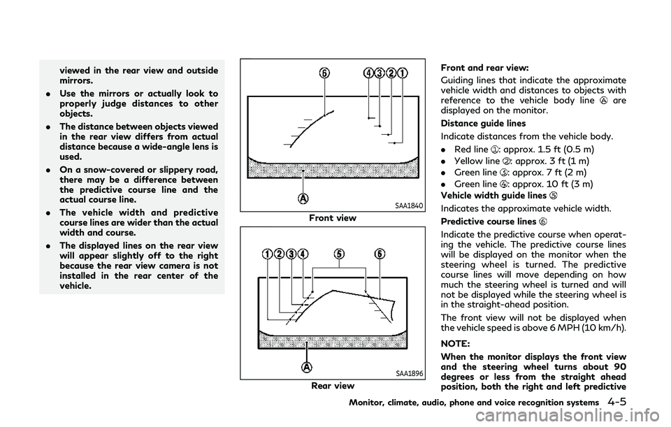
SAA1840
Front view
SAA1896
Rear view Front and rear view:
Guiding lines that indicate the approximate
vehicle width and distances to objects with
reference to the vehicle body line
are
displayed on the monitor.
Distance guide lines
Indicate distances from the vehicle body.
. Red line
: approx. 1.5 ft (0.5 m)
. Yellow line
: approx. 3 ft (1 m)
. Green line
: approx. 7 ft (2 m)
. Green line
: approx. 10 ft (3 m)
Vehicle width guide lines
Indicates the approximate vehicle width.
Predictive course lines
Indicate the predictive course when operat-
ing the vehicle. The predictive course lines
will be displayed on the monitor when the
steering wheel is turned. The predictive
course lines will move depending on how
much the steering wheel is turned and will
not be displayed while the steering wheel is
in the straight-ahead position.
The front view will not be displayed when
the vehicle speed is above 6 MPH (10 km/h).
NOTE:
When the monitor displays the front view
and the steering wheel turns about 90
degrees or less from the straight ahead
position, both the right and left predictive
Monitor, climate, audio, phone and voice recognition systems4-5