width INFINITI QX80 2018 Owners Manual
[x] Cancel search | Manufacturer: INFINITI, Model Year: 2018, Model line: QX80, Model: INFINITI QX80 2018Pages: 522, PDF Size: 2.41 MB
Page 217 of 522
4-4Monitor, climate, audio, phone and voice recognition systems
The monitor displays various views of the
position of the vehicle in a split screen
format. All views are not available at all
times.
Available views:
.Front view
An approximately 150-degree view of
the front of the vehicle.
. Rear view
An approximately 150-degree view of
the rear of the vehicle.
. Bird’s-eye view
The surrounding view of the vehicle from
above.
. Front-side view
The view around and ahead of the front
passenger’s side wheel.
. Front-wide view
An approximately 180-degree view of
the front of the vehicle.
. Rear-wide view
An approximately 180-degree view of
the rear of the vehicle.
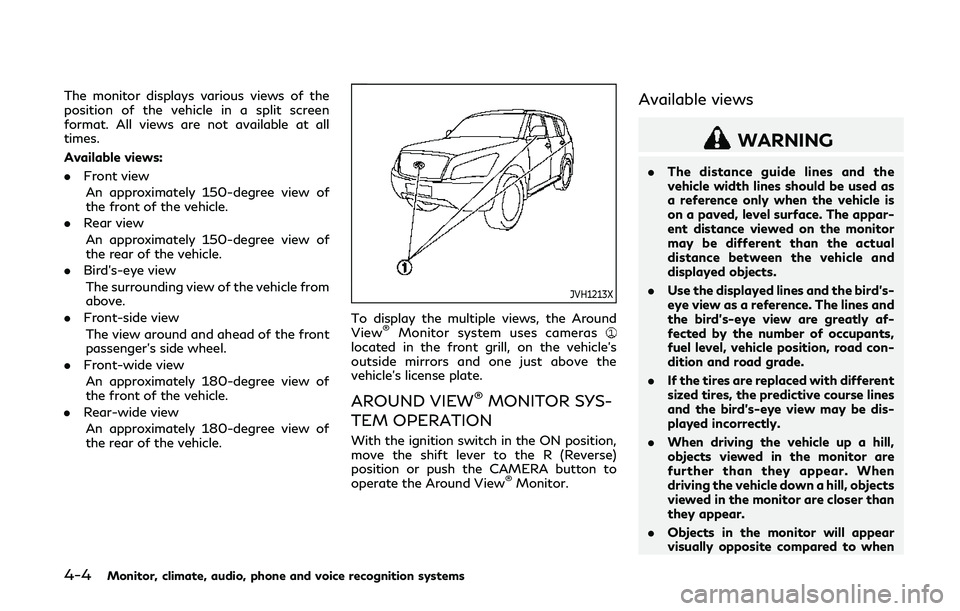
JVH1213X
To display the multiple views, the Around
View®Monitor system uses cameraslocated in the front grill, on the vehicle’s
outside mirrors and one just above the
vehicle’s license plate.
AROUND VIEW®MONITOR SYS-
TEM OPERATION
With the ignition switch in the ON position,
move the shift lever to the R (Reverse)
position or push the CAMERA button to
operate the Around View
®Monitor.
Available views
WARNING
. The distance guide lines and the
vehicle width lines should be used as
a reference only when the vehicle is
on a paved, level surface. The appar-
ent distance viewed on the monitor
may be different than the actual
distance between the vehicle and
displayed objects.
. Use the displayed lines and the bird’s-
eye view as a reference. The lines and
the bird’s-eye view are greatly af-
fected by the number of occupants,
fuel level, vehicle position, road con-
dition and road grade.
. If the tires are replaced with different
sized tires, the predictive course lines
and the bird’s-eye view may be dis-
played incorrectly.
. When driving the vehicle up a hill,
objects viewed in the monitor are
further than they appear. When
driving the vehicle down a hill, objects
viewed in the monitor are closer than
they appear.
. Objects in the monitor will appear
visually opposite compared to when
Page 218 of 522
viewed in the rear view and outside
mirrors.
. Use the mirrors or actually look to
properly judge distances to other
objects.
. The distance between objects viewed
in the rear view differs from actual
distance because a wide-angle lens is
used.
. On a snow-covered or slippery road,
there may be a difference between
the predictive course line and the
actual course line.
. The vehicle width and predictive
course lines are wider than the actual
width and course.
. The displayed lines on the rear view
will appear slightly off to the right
because the rear view camera is not
installed in the rear center of the
vehicle.
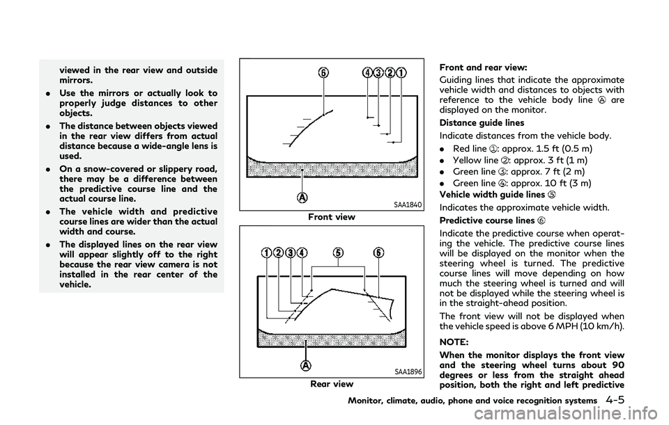
SAA1840
Front view
SAA1896
Rear view Front and rear view:
Guiding lines that indicate the approximate
vehicle width and distances to objects with
reference to the vehicle body line
are
displayed on the monitor.
Distance guide lines
Indicate distances from the vehicle body.
. Red line
: approx. 1.5 ft (0.5 m)
. Yellow line
: approx. 3 ft (1 m)
. Green line
: approx. 7 ft (2 m)
. Green line
: approx. 10 ft (3 m)
Vehicle width guide lines
Indicates the approximate vehicle width.
Predictive course lines
Indicate the predictive course when operat-
ing the vehicle. The predictive course lines
will be displayed on the monitor when the
steering wheel is turned. The predictive
course lines will move depending on how
much the steering wheel is turned and will
not be displayed while the steering wheel is
in the straight-ahead position.
The front view will not be displayed when
the vehicle speed is above 6 MPH (10 km/h).
NOTE:
When the monitor displays the front view
and the steering wheel turns about 90
degrees or less from the straight ahead
position, both the right and left predictive
Monitor, climate, audio, phone and voice recognition systems4-5
Page 220 of 522
WARNING
.Objects in the bird’s-eye view will
appear further than the actual dis-
tance.
. Tall objects, such as a curb or vehicle,
may be misaligned or not displayed at
the seam of the views.
. Objects that are above the camera
cannot be displayed.
. The view for the bird’s-eye view may
be misaligned when the camera posi-
tion alters.
. A line on the ground may be mis-
aligned and is not seen as being
straight at the seam of the views.
The misalignment will increase as the
line proceeds away from the vehicle.
. Tire angle display does not indicate
the actual tire angle.
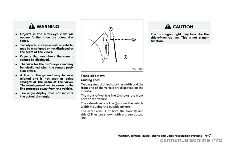
JVH1141X
Front-side view:
Guiding lines:
Guiding lines that indicate the width and the
front end of the vehicle are displayed on the
monitor.
The front-of-vehicle line
shows the front
part of the vehicle.
The side-of-vehicle line
shows the vehicle
width including the outside mirrors.
The extensions
of both the frontand
sidelines are shown with a green dotted
line.
CAUTION
The turn signal light may look like the
side-of-vehicle line. This is not a mal-
function.
Monitor, climate, audio, phone and voice recognition systems4-7
Page 221 of 522
4-8Monitor, climate, audio, phone and voice recognition systems
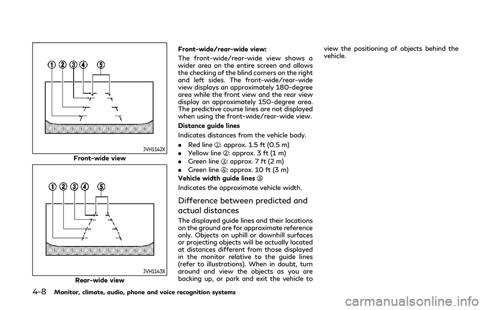
JVH1142X
Front-wide view
JVH1143X
Rear-wide viewFront-wide/rear-wide view:
The front-wide/rear-wide view shows a
wider area on the entire screen and allows
the checking of the blind corners on the right
and left sides. The front-wide/rear-wide
view displays an approximately 180-degree
area while the front view and the rear view
display an approximately 150-degree area.
The predictive course lines are not displayed
when using the front-wide/rear-wide view.
Distance guide lines
Indicates distances from the vehicle body.
.
Red line
: approx. 1.5 ft (0.5 m)
. Yellow line
: approx. 3 ft (1 m)
. Green line
: approx. 7 ft (2 m)
. Green line
: approx. 10 ft (3 m)
Vehicle width guide lines
Indicates the approximate vehicle width.
Difference between predicted and
actual distances
The displayed guide lines and their locations
on the ground are for approximate reference
only. Objects on uphill or downhill surfaces
or projecting objects will be actually located
at distances different from those displayed
in the monitor relative to the guide lines
(refer to illustrations). When in doubt, turn
around and view the objects as you are
backing up, or park and exit the vehicle to view the positioning of objects behind the
vehicle.
Page 222 of 522
JVH1214X
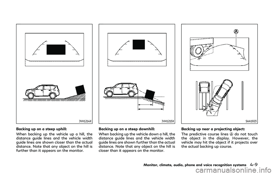
Backing up on a steep uphill:
When backing up the vehicle up a hill, the
distance guide lines and the vehicle width
guide lines are shown closer than the actual
distance. Note that any object on the hill is
further than it appears on the monitor.
JVH1215X
Backing up on a steep downhill:
When backing up the vehicle down a hill, the
distance guide lines and the vehicle width
guide lines are shown further than the actual
distance. Note that any object on the hill is
closer than it appears on the monitor.
SAA1923
Backing up near a projecting object:
The predictive course lines
do not touch
the object in the display. However, the
vehicle may hit the object if it projects over
the actual backing up course.
Monitor, climate, audio, phone and voice recognition systems4-9
Page 224 of 522
SAA1898
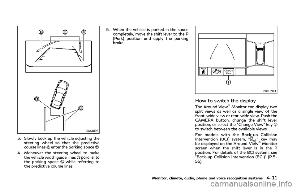
3. Slowly back up the vehicle adjusting thesteering wheel so that the predictive
course lines
enter the parking space.
4. Maneuver the steering wheel to make the vehicle width guide lines
parallel to
the parking spacewhile referring to
the predictive course lines. 5. When the vehicle is parked in the space
completely, move the shift lever to the P
(Park) position and apply the parking
brake.
JVH1691X
How to switch the display
The Around View®Monitor can display two
split views as well as a single view of the
front-wide view or rear-wide view. Push the
CAMERA button, change the shift lever
position, or select the “Change View” key
to switch between the available views.
For models with the Back-up Collision
Intervention (BCI) system, “
” key may
be displayed on the Around View®Monitor
screen when the shift lever is in the R
position. For details of the BCI system, see
“Back-up Collision Intervention (BCI)” (P.5-
55).
Monitor, climate, audio, phone and voice recognition systems4-11
Page 279 of 522
![INFINITI QX80 2018 Owners Manual 5-28Starting and driving
JVS1043X
HOW TO ENABLE/DISABLE THE
LDP SYSTEM
Perform the following steps to enable or
disable the LDP system.
1. Push the SETTING button
.
2. Touch [Driver Assistance].
3. To INFINITI QX80 2018 Owners Manual 5-28Starting and driving
JVS1043X
HOW TO ENABLE/DISABLE THE
LDP SYSTEM
Perform the following steps to enable or
disable the LDP system.
1. Push the SETTING button
.
2. Touch [Driver Assistance].
3. To](/img/42/41145/w960_41145-278.png)
5-28Starting and driving
JVS1043X
HOW TO ENABLE/DISABLE THE
LDP SYSTEM
Perform the following steps to enable or
disable the LDP system.
1. Push the SETTING button
.
2. Touch [Driver Assistance].
3. Touch [Lane Assist].
4. Touch [Lane Departure Prevention] to turn the system ON/OFF.
LDW/LDP SYSTEM LIMITATIONS
WARNING
Listed below are the system limitations
for the LDW and LDP systems. Failure to
operate the vehicle in accordance with
these system limitations could result in
serious injury or death.
.The system will not operate at speeds
below 45 MPH (70 km/h) or if it
cannot detect lane markers.
. The LDP system is primarily intended
for use on well-developed freeways
or highways. It may not detect the
lane markers in certain roads, weath-
er or driving conditions.
. Do not use the LDP system under the
following conditions as it may not
function properly:
— During bad weather (rain, fog, snow, etc.).
— When driving on slippery roads, such as on ice or snow, etc.
— When driving on winding or un- even roads.
— When there is a lane closure due to road repairs. — When driving in a makeshift or
temporary lane.
— When driving on roads where the lane width is too narrow.
— When driving without normal tire conditions (for example, tire wear,
low tire pressure, installation of
spare tire, tire chains, non-stan-
dard wheels).
— When the vehicle is equipped with non-original brake parts or sus-
pension parts.
— When you are towing a trailer or other vehicle.
. The camera may not detect lane
markers in the following situations
and the LDW and LDP systems may
not operate properly.
— On roads where there are multi- ple parallel lane markers, lane
markers that are faded or not
painted clearly, yellow painted
lane markers, non-standard lane
markers, or lane markers covered
with water, dirt, snow, etc.
— On roads where the discontinued lane markers are still detectable.
— On roads where there are sharp curves.
Page 288 of 522
— A vehicle which your vehicle over-takes rapidly.
— A vehicle that passes through the detection zone quickly.
. The radar sensor’s detection zone is
designed based on a standard lane
width. When driving in a wider lane,
the radar sensors may not detect
vehicles in an adjacent lane. When
driving in a narrow lane, the radar
sensors may detect vehicles driving
two lanes away.
. The radar sensors are designed to
ignore most stationary objects, how-
ever objects such as guardrails, walls,
foliage and parked vehicles may oc-
casionally be detected. This is a
normal operation condition.
. The following conditions may reduce
the ability of the radar to detect
other vehicles:
— Severe weather
— Road spray
— Ice/frost/snow build-up on the vehicle
— Dirt build-up on the vehicle
. Do not attach stickers (including
transparent material), install acces-
sories or apply additional paint near the radar sensors. These conditions
may reduce the ability of the radar to
detect other vehicles.
. Excessive noise (for example, audio
system volume, open vehicle window)
will interfere with the chime sound,
and it may not be heard.
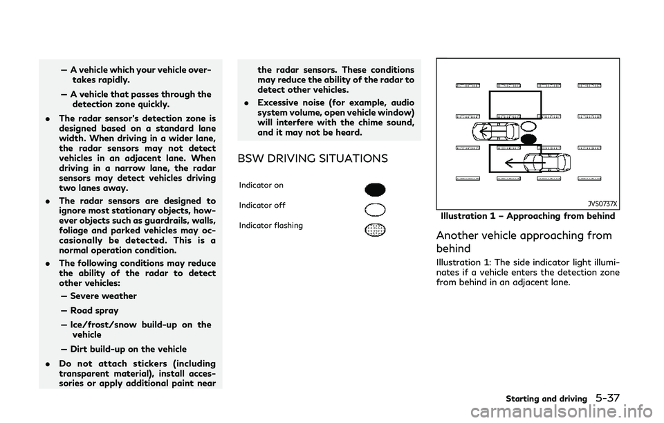
BSW DRIVING SITUATIONS
Indicator on
Indicator off
Indicator flashing
JVS0737X
Illustration 1 – Approaching from behind
Another vehicle approaching from
behind
Illustration 1: The side indicator light illumi-
nates if a vehicle enters the detection zone
from behind in an adjacent lane.
Starting and driving5-37
Page 297 of 522
![INFINITI QX80 2018 Owners Manual 5-46Starting and driving
JVS1043X
HOW TO ENABLE/DISABLE THE
BSI SYSTEM
Perform the following steps to enable or
disable the BSI system.
1. Push the SETTING button
.
2. Touch [Driver Assistance].
3. To INFINITI QX80 2018 Owners Manual 5-46Starting and driving
JVS1043X
HOW TO ENABLE/DISABLE THE
BSI SYSTEM
Perform the following steps to enable or
disable the BSI system.
1. Push the SETTING button
.
2. Touch [Driver Assistance].
3. To](/img/42/41145/w960_41145-296.png)
5-46Starting and driving
JVS1043X
HOW TO ENABLE/DISABLE THE
BSI SYSTEM
Perform the following steps to enable or
disable the BSI system.
1. Push the SETTING button
.
2. Touch [Driver Assistance].
3. Touch [Blind Spot Assist].
4. Touch [Blind Spot Intervention] to turn the system ON/OFF.
BSI SYSTEM LIMITATIONS
WARNING
Listed below are the system limitations
for the BSI system. Failure to operate
the vehicle in accordance with these
system limitations could result in serious
injury or death.
.The BSI system cannot detect all
vehicles under all conditions.
. The radar sensors may not be able to
detect and activate BSI when certain
objects are present such as:
— Pedestrians, bicycles, animals.
— Vehicles such as motorcycles, low height vehicles, or high ground
clearance vehicles.
— Vehicles remaining in the detec- tion zone when you accelerate
from a stop.
— Oncoming vehicles.
— A vehicle merging into an adja- cent lane at a speed approxi-
mately the same as your vehicle.
— A vehicle approaching rapidly from behind. — A vehicle which your vehicle over-
takes rapidly.
— A vehicle that passes through the detection zone quickly.
. The radar sensor’s detection zone is
designed based on a standard lane
width. When driving in a wider lane,
the radar sensors may not detect
vehicles in an adjacent lane. When
driving in a narrow lane, the radar
sensors may detect vehicles driving
two lanes away.
. The radar sensors are designed to
ignore most stationary objects, how-
ever objects such as guardrails, walls,
foliage and parked vehicles may oc-
casionally be detected. This is a
normal operation condition.
. The camera may not detect lane
markers in the following situations
and the BSI system may not operate
properly.
— On roads where there are multi- ple parallel lane markers; lane
markers that are faded or not
painted clearly; yellow painted
lane markers; non-standard lane
markers; lane markers covered
with water, dirt, snow, etc.
Page 298 of 522
— On roads where discontinued lanemarkers are still detectable.
— On roads where there are sharp curves.
— On roads where there are sharply contrasting objects, such as sha-
dows, snow, water, wheel ruts,
seams or lines remaining after
road repairs.
— On roads where the traveling lane merges or separates.
— When the vehicle’s traveling di- rection does not align with the
lane markers.
— When traveling close to the ve- hicle in front of you, which ob-
structs the lane camera unit
detection range.
— When rain, snow or dirt adheres to the windshield in front of a lane
camera unit.
— When the headlights are not bright due to dirt on the lens or
if aiming is not adjusted properly.
— When strong light enters a lane camera unit. (For example: light
directly shines on the front of the
vehicle at sunrise or sunset.) — When a sudden change in bright-
ness occurs. (For example: when
the vehicle enters or exits a tunnel
or under a bridge.)
. Do not use the BSI system under the
following conditions because the sys-
tem may not function properly.
— During bad weather. (For exam- ple: rain, fog, snow, etc.)
— When driving on slippery roads, such as on ice or snow, etc.
— When driving on winding or un- even roads.
— When there is a lane closure due to road repairs.
— When driving in a makeshift or temporary lane.
— When driving on roads where the lane width is too narrow.
— When driving with a tire that is not within normal tire conditions
(for example, tire wear, low tire
pressure, installation of spare tire,
tire chains, non-standard wheels).
— When the vehicle is equipped with non-original brake parts or sus-
pension parts. — When towing a trailer or other
vehicle.
. Excessive noise (for example, audio
system volume, open vehicle window)
will interfere with the chime sound,
and it may not be heard.
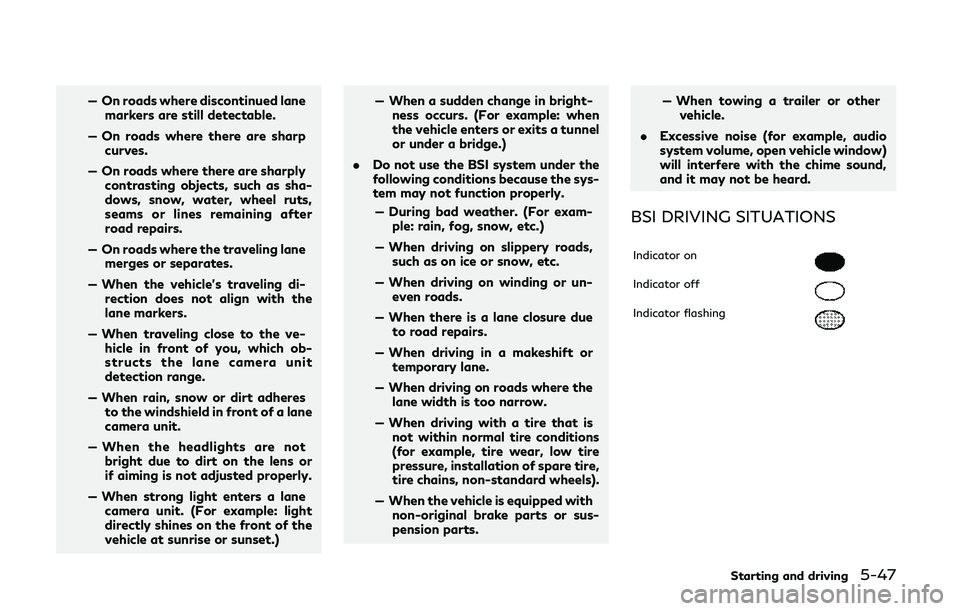
BSI DRIVING SITUATIONS
Indicator on
Indicator off
Indicator flashing
Starting and driving5-47