relay ISUZU AXIOM 2002 Service Owner's Manual
[x] Cancel search | Manufacturer: ISUZU, Model Year: 2002, Model line: AXIOM, Model: ISUZU AXIOM 2002Pages: 2100, PDF Size: 19.35 MB
Page 750 of 2100
5C±70
POWER±ASSISTED BRAKE SYSTEM
Hydraulic Brakes
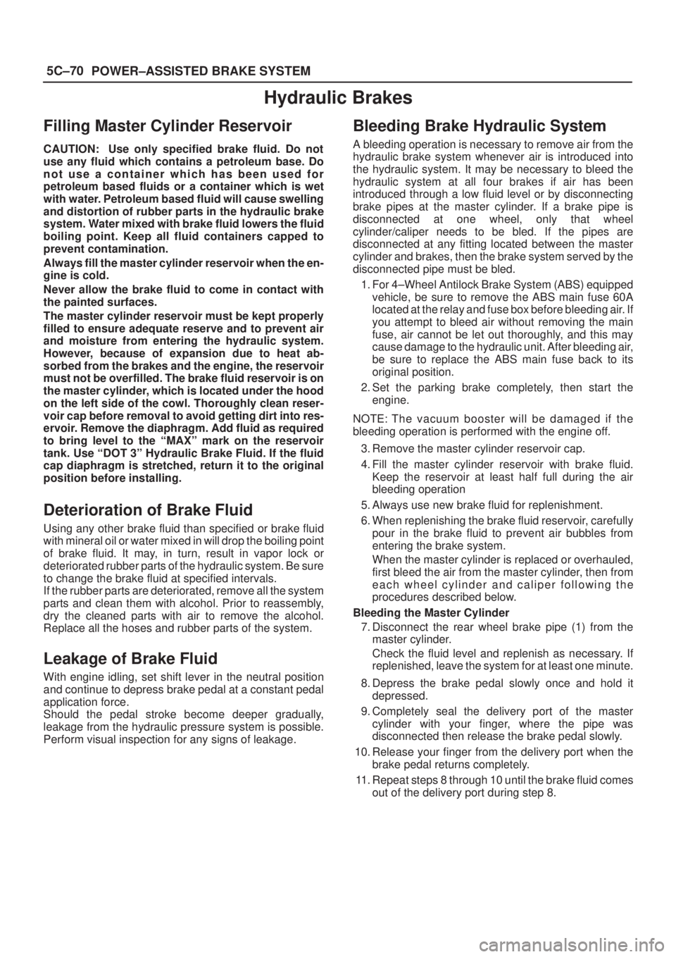
Filling Master Cylinder Reservoir
CAUTION: Use only specified brake fluid. Do not
use any fluid which contains a petroleum base. Do
not use a container which has been used for
petroleum based fluids or a container which is wet
with water. Petroleum based fluid will cause swelling
and distortion of rubber parts in the hydraulic brake
system. Water mixed with brake fluid lowers the fluid
boiling point. Keep all fluid containers capped to
prevent contamination.
Always fill the master cylinder reservoir when the en-
gine is cold.
Never allow the brake fluid to come in contact with
the painted surfaces.
The master cylinder reservoir must be kept properly
filled to ensure adequate reserve and to prevent air
and moisture from entering the hydraulic system.
However, because of expansion due to heat ab-
sorbed from the brakes and the engine, the reservoir
must not be overfilled. The brake fluid reservoir is on
the master cylinder, which is located under the hood
on the left side of the cowl. Thoroughly clean reser-
voir cap before removal to avoid getting dirt into res-
ervoir. Remove the diaphragm. Add fluid as required
to bring level to the ªMAXº mark on the reservoir
tank. Use ªDOT 3º Hydraulic Brake Fluid. If the fluid
cap diaphragm is stretched, return it to the original
position before installing.
Deterioration of Brake Fluid
Using any other brake fluid than specified or brake fluid
with mineral oil or water mixed in will drop the boiling point
of brake fluid. It may, in turn, result in vapor lock or
deteriorated rubber parts of the hydraulic system. Be sure
to change the brake fluid at specified intervals.
If the rubber parts are deteriorated, remove all the system
parts and clean them with alcohol. Prior to reassembly,
dry the cleaned parts with air to remove the alcohol.
Replace all the hoses and rubber parts of the system.
Leakage of Brake Fluid
With engine idling, set shift lever in the neutral position
and continue to depress brake pedal at a constant pedal
application force.
Should the pedal stroke become deeper gradually,
leakage from the hydraulic pressure system is possible.
Perform visual inspection for any signs of leakage.
Bleeding Brake Hydraulic System
A bleeding operation is necessary to remove air from the
hydraulic brake system whenever air is introduced into
the hydraulic system. It may be necessary to bleed the
hydraulic system at all four brakes if air has been
introduced through a low fluid level or by disconnecting
brake pipes at the master cylinder. If a brake pipe is
disconnected at one wheel, only that wheel
cylinder/caliper needs to be bled. If the pipes are
disconnected at any fitting located between the master
cylinder and brakes, then the brake system served by the
disconnected pipe must be bled.
1. For 4±Wheel Antilock Brake System (ABS) equipped
vehicle, be sure to remove the ABS main fuse 60A
located at the relay and fuse box before bleeding air. If
you attempt to bleed air without removing the main
fuse, air cannot be let out thoroughly, and this may
cause damage to the hydraulic unit. After bleeding air,
be sure to replace the ABS main fuse back to its
original position.
2. Set the parking brake completely, then start the
engine.
NOTE: The vacuum booster will be damaged if the
bleeding operation is performed with the engine off.
3. Remove the master cylinder reservoir cap.
4. Fill the master cylinder reservoir with brake fluid.
Keep the reservoir at least half full during the air
bleeding operation
5. Always use new brake fluid for replenishment.
6. When replenishing the brake fluid reservoir, carefully
pour in the brake fluid to prevent air bubbles from
entering the brake system.
When the master cylinder is replaced or overhauled,
first bleed the air from the master cylinder, then from
each wheel cylinder and caliper following the
procedures described below.
Bleeding the Master Cylinder
7. Disconnect the rear wheel brake pipe (1) from the
master cylinder.
Check the fluid level and replenish as necessary. If
replenished, leave the system for at least one minute.
8. Depress the brake pedal slowly once and hold it
depressed.
9. Completely seal the delivery port of the master
cylinder with your finger, where the pipe was
disconnected then release the brake pedal slowly.
10. Release your finger from the delivery port when the
brake pedal returns completely.
11. Repeat steps 8 through 10 until the brake fluid comes
out of the delivery port during step 8.
Page 815 of 2100
6A±5
ENGINE MECHANICAL (6VE1 3.5L)
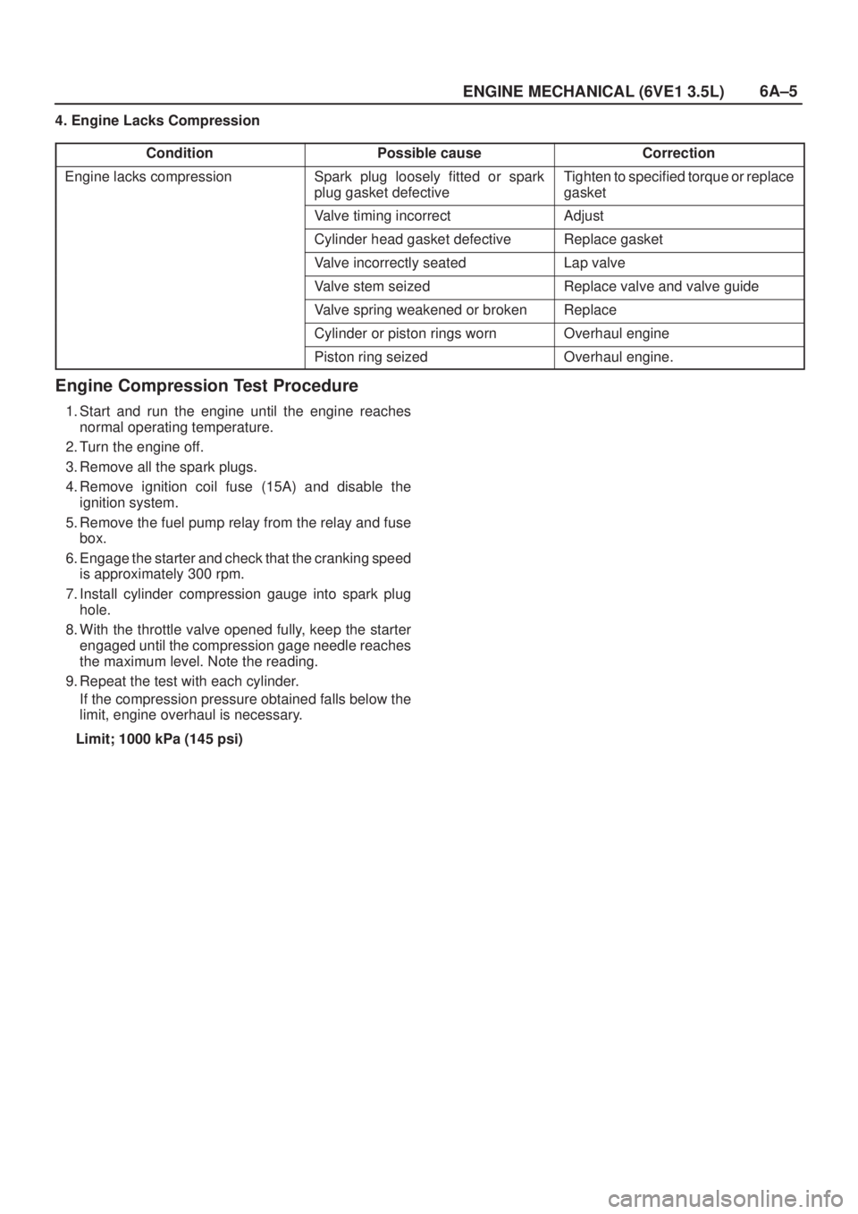
4. Engine Lacks Compression
Condition
Possible causeCorrection
Engine lacks compressionSpark plug loosely fitted or spark
plug gasket defectiveTighten to specified torque or replace
gasket
Valve timing incorrectAdjust
Cylinder head gasket defectiveReplace gasket
Valve incorrectly seatedLap valve
Valve stem seizedReplace valve and valve guide
Valve spring weakened or brokenReplace
Cylinder or piston rings wornOverhaul engine
Piston ring seizedOverhaul engine.
Engine Compression Test Procedure
1. Start and run the engine until the engine reaches
normal operating temperature.
2. Turn the engine off.
3. Remove all the spark plugs.
4. Remove ignition coil fuse (15A) and disable the
ignition system.
5. Remove the fuel pump relay from the relay and fuse
box.
6. Engage the starter and check that the cranking speed
is approximately 300 rpm.
7. Install cylinder compression gauge into spark plug
hole.
8. With the throttle valve opened fully, keep the starter
engaged until the compression gage needle reaches
the maximum level. Note the reading.
9. Repeat the test with each cylinder.
If the compression pressure obtained falls below the
limit, engine overhaul is necessary.
Limit; 1000 kPa (145 psi)
Page 816 of 2100
6A±6
ENGINE MECHANICAL (6VE1 3.5L)
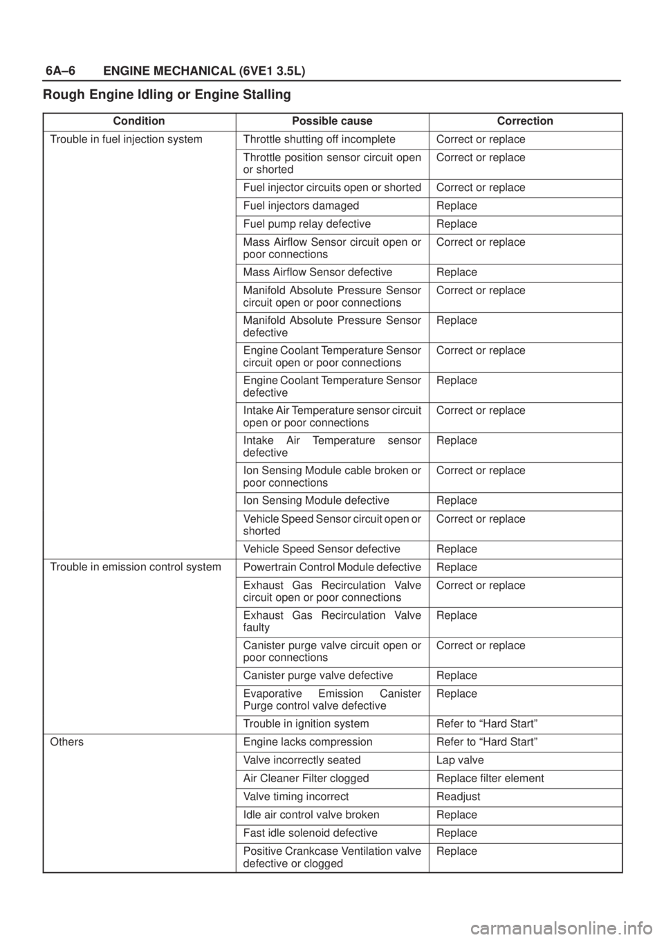
Rough Engine Idling or Engine Stalling
ConditionPossible causeCorrection
Trouble in fuel injection systemThrottle shutting off incompleteCorrect or replace
Throttle position sensor circuit open
or shortedCorrect or replace
Fuel injector circuits open or shortedCorrect or replace
Fuel injectors damagedReplace
Fuel pump relay defectiveReplace
Mass Airflow Sensor circuit open or
poor connectionsCorrect or replace
Mass Airflow Sensor defectiveReplace
Manifold Absolute Pressure Sensor
circuit open or poor connectionsCorrect or replace
Manifold Absolute Pressure Sensor
defectiveReplace
Engine Coolant Temperature Sensor
circuit open or poor connectionsCorrect or replace
Engine Coolant Temperature Sensor
defectiveReplace
Intake Air Temperature sensor circuit
open or poor connectionsCorrect or replace
Intake Air Temperature sensor
defectiveReplace
Ion Sensing Module cable broken or
poor connectionsCorrect or replace
Ion Sensing Module defectiveReplace
Vehicle Speed Sensor circuit open or
shortedCorrect or replace
Vehicle Speed Sensor defectiveReplace
Trouble in emission control systemPowertrain Control Module defectiveReplace
Exhaust Gas Recirculation Valve
circuit open or poor connectionsCorrect or replace
Exhaust Gas Recirculation Valve
faultyReplace
Canister purge valve circuit open or
poor connectionsCorrect or replace
Canister purge valve defectiveReplace
Evaporative Emission Canister
Purge control valve defectiveReplace
Trouble in ignition systemRefer to ªHard Startº
OthersEngine lacks compressionRefer to ªHard Startº
Valve incorrectly seatedLap valve
Air Cleaner Filter cloggedReplace filter element
Valve timing incorrectReadjust
Idle air control valve brokenReplace
Fast idle solenoid defectiveReplace
Positive Crankcase Ventilation valve
defective or cloggedReplace
Page 824 of 2100

6A±14
ENGINE MECHANICAL (6VE1 3.5L)
Abnormal Combustion
ConditionPossible causeCorrection
Trouble in fuel systemFuel pressure control valve defectiveReplace
Fuel filter cloggedReplace
Fuel pump cloggedClean or replace
Fuel tank or fuel pipe cloggedClean or replace
Fuel injector cloggedClean or replace
Fuel pump relay defectiveReplace
Power supply cable for fuel pump
broken or poor connectionsReconnect, correct or replace
Mass Airflow (MAF) Sensor circuit
open or defectiveCorrect or replace
MAF Sensor defectiveReplace
Manifold Absolute Pressure Sensor
circuit open or shortedCorrect or replace
Manifold Absolute Pressure Sensor
defectiveReplace
Engine Coolant Temperature (ECT)
Sensor circuit open or shortedCorrect or replace
ECT Sensor defectiveReplace
Throttle Position Sensor adjustment
incorrectReadjust
Throttle Position Sensor defectiveReplace
Throttle Position Sensor connector
poor connectionsReconnect
Vehicle Speed Sensor cable poor
connections or defectiveCorrect or replace
Vehicle Speed Sensor loosely fixedFix tightly
Vehicle Speed Sensor in wrong
contact or defectiveReplace
Powertrain Control Module cable
poor connections or defectiveCorrect or replace
Trouble in emission control systemHeated Oxygen Sensor circuit openCorrect or replace
Heated Oxygen Sensor defectiveReplace
Signal vacuum hose loosely fitted or
defectiveCorrect or replace
EGR Valve circuit open or shortedCorrect or replace
Exhaust Gas Recirculation Valve
defectiveReplace
ECT Sensor circuit open or shortedCorrect or replace
Canister Purge Valve circuit open or
shortedCorrect or replace
Canister Purge Valve defectiveReplace
ECT Sensor defectiveReplace
Positive Crankcase Ventilation
(PCV) valve and hose cloggedCorrect or replace
Evaporator systemRefer to Section 6E
Trouble in ignition systemÐÐÐÐRefer to ªEngine Lacks Powerº
Page 918 of 2100
6C±1 ENGINE FUEL (6VE1 3.5L)
AXIOM
ENGINE
ENGINE FUEL
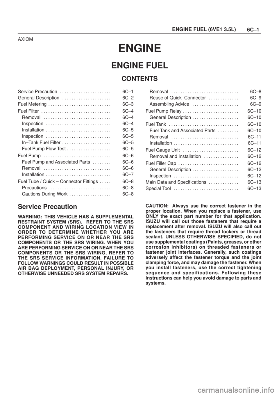
CONTENTS
Service Precaution 6C±1. . . . . . . . . . . . . . . . . . . . . .
General Description 6C±2. . . . . . . . . . . . . . . . . . . . .
Fuel Metering 6C±3. . . . . . . . . . . . . . . . . . . . . . . . . . .
Fuel Filter 6C±4. . . . . . . . . . . . . . . . . . . . . . . . . . . . . .
Removal 6C±4. . . . . . . . . . . . . . . . . . . . . . . . . . . . .
Inspection 6C±4. . . . . . . . . . . . . . . . . . . . . . . . . . . .
Installation 6C±5. . . . . . . . . . . . . . . . . . . . . . . . . . . .
Inspection 6C±5. . . . . . . . . . . . . . . . . . . . . . . . . . . .
In±Tank Fuel Filter 6C±5. . . . . . . . . . . . . . . . . . . . .
Fuel Pump Flow Test 6C±5. . . . . . . . . . . . . . . . . . .
Fuel Pump 6C±6. . . . . . . . . . . . . . . . . . . . . . . . . . . . .
Fuel Pump and Associated Parts 6C±6. . . . . . . .
Removal 6C±6. . . . . . . . . . . . . . . . . . . . . . . . . . . . .
Installation 6C±7. . . . . . . . . . . . . . . . . . . . . . . . . . . .
Fuel Tube / Quick ± Connector Fittings 6C±8. . . . .
Precautions 6C±8. . . . . . . . . . . . . . . . . . . . . . . . . . .
Cautions During Work 6C±8. . . . . . . . . . . . . . . . . . Removal 6C±8. . . . . . . . . . . . . . . . . . . . . . . . . . . . .
Reuse of Quick±Connector 6C±9. . . . . . . . . . . . .
Assembling Advice 6C±9. . . . . . . . . . . . . . . . . . . .
Fuel Pump Relay 6C±10. . . . . . . . . . . . . . . . . . . . . . . .
General Description 6C±10. . . . . . . . . . . . . . . . . . . .
Fuel Tank 6C±10. . . . . . . . . . . . . . . . . . . . . . . . . . . . . .
Fuel Tank and Associated Parts 6C±10. . . . . . . . .
Removal 6C±11. . . . . . . . . . . . . . . . . . . . . . . . . . . . .
Installation 6C±11. . . . . . . . . . . . . . . . . . . . . . . . . . . .
Fuel Gauge Unit 6C±12. . . . . . . . . . . . . . . . . . . . . . . .
Removal and Installation 6C±12. . . . . . . . . . . . . . .
Fuel Filler Cap 6C±12. . . . . . . . . . . . . . . . . . . . . . . . . .
General Description 6C±12. . . . . . . . . . . . . . . . . . . .
Inspection 6C±12. . . . . . . . . . . . . . . . . . . . . . . . . . . .
Main Data and Specifications 6C±13. . . . . . . . . . . . .
Special Tool 6C±13. . . . . . . . . . . . . . . . . . . . . . . . . . . .
Service Precaution
WARNING: THIS VEHICLE HAS A SUPPLEMENTAL
RESTRAINT SYSTEM (SRS). REFER TO THE SRS
COMPONENT AND WIRING LOCATION VIEW IN
ORDER TO DETERMINE WHETHER YOU ARE
PERFORMING SERVICE ON OR NEAR THE SRS
COMPONENTS OR THE SRS WIRING. WHEN YOU
ARE PERFORMING SERVICE ON OR NEAR THE SRS
COMPONENTS OR THE SRS WIRING, REFER TO
THE SRS SERVICE INFORMATION. FAILURE TO
FOLLOW WARNINGS COULD RESULT IN POSSIBLE
AIR BAG DEPLOYMENT, PERSONAL INJURY, OR
OTHERWISE UNNEEDED SRS SYSTEM REPAIRS.CAUTION: Always use the correct fastener in the
proper location. When you replace a fastener, use
ONLY the exact part number for that application.
ISUZU will call out those fasteners that require a
replacement after removal. ISUZU will also call out
the fasteners that require thread lockers or thread
sealant. UNLESS OTHERWISE SPECIFIED, do not
use supplemental coatings (Paints, greases, or other
corrosion inhibitors) on threaded fasteners or
fastener joint interfaces. Generally, such coatings
adversely affect the fastener torque and the joint
clamping force, and may damage the fastener. When
you install fasteners, use the correct tightening
sequence and specifications. Following these
instructions can help you avoid damage to parts and
systems.
Page 922 of 2100
6C±5 ENGINE FUEL (6VE1 3.5L)
Installation
1. Install the fuel filter in the proper direction.
2. Install fuel filter holder fixing bolt.
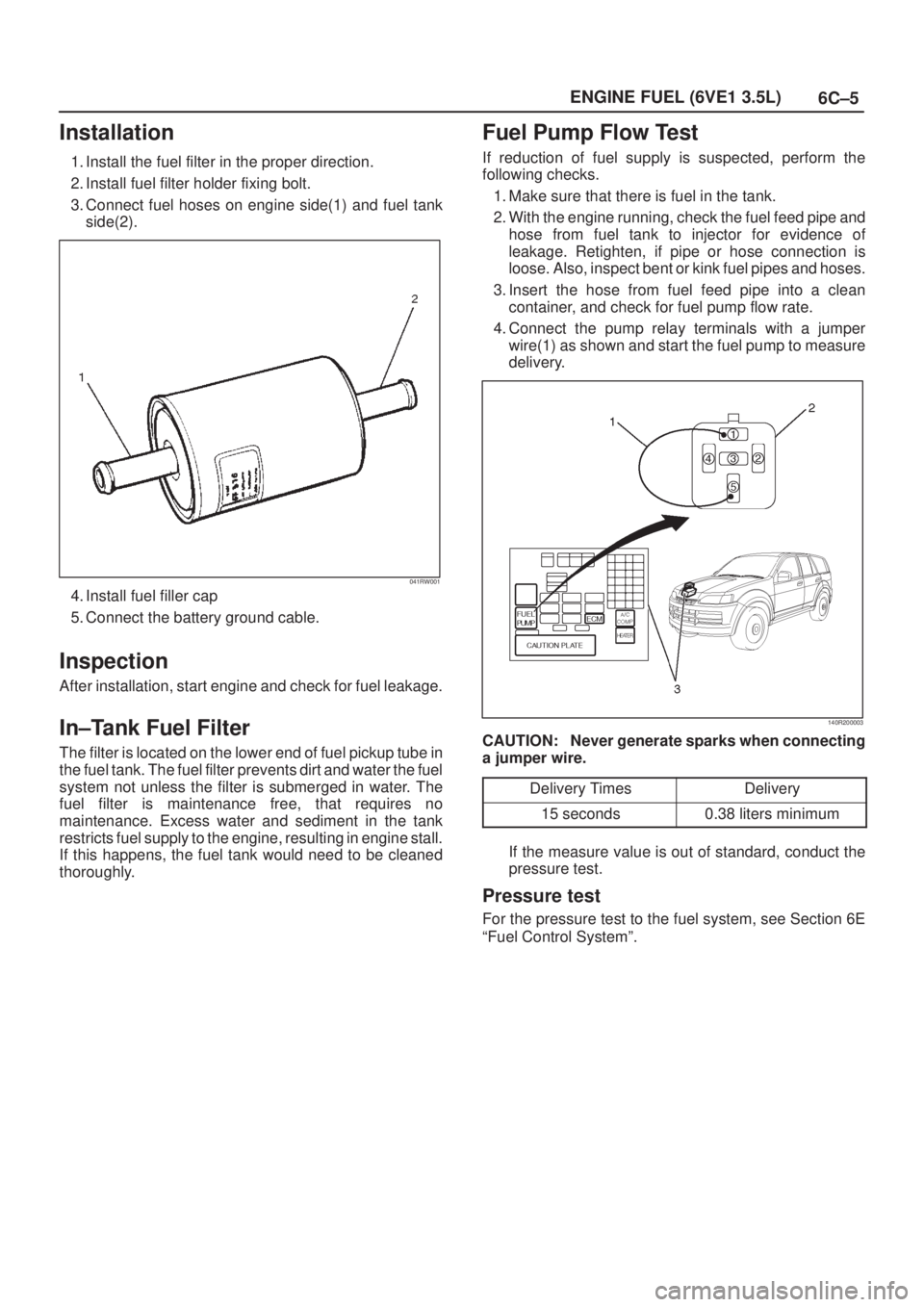
3. Connect fuel hoses on engine side(1) and fuel tank
side(2).
041RW001
4. Install fuel filler cap
5. Connect the battery ground cable.
Inspection
After installation, start engine and check for fuel leakage.
In±Tank Fuel Filter
The filter is located on the lower end of fuel pickup tube in
the fuel tank. The fuel filter prevents dirt and water the fuel
system not unless the filter is submerged in water. The
fuel filter is maintenance free, that requires no
maintenance. Excess water and sediment in the tank
restricts fuel supply to the engine, resulting in engine stall.
If this happens, the fuel tank would need to be cleaned
thoroughly.
Fuel Pump Flow Test
If reduction of fuel supply is suspected, perform the
following checks.
1. Make sure that there is fuel in the tank.
2. With the engine running, check the fuel feed pipe and
hose from fuel tank to injector for evidence of
leakage. Retighten, if pipe or hose connection is
loose. Also, inspect bent or kink fuel pipes and hoses.
3. Insert the hose from fuel feed pipe into a clean
container, and check for fuel pump flow rate.
4. Connect the pump relay terminals with a jumper
wire(1) as shown and start the fuel pump to measure
delivery.
140R200003
CAUTION: Never generate sparks when connecting
a jumper wire.
Delivery Times
Delivery
15 seconds0.38 liters minimum
If the measure value is out of standard, conduct the
pressure test.
Pressure test
For the pressure test to the fuel system, see Section 6E
ªFuel Control Systemº.
Page 927 of 2100

6C±10
ENGINE FUEL (6VE1 3.5L)
Fuel Pump Relay
General Description
In order to control the fuel pump and sender (FPS)
operation, the FPS relay is provided. When the starter
switch is turned to ªONº position, the FPS relay operates
the FPS for 2 seconds.
When the key is turned to ªSTARTº position, the Engine
Control Module receives the reference pulse from the
Ignition Control Module and it operates the relay, again
causing the FPS to feed fuel.
Fuel Tank
Fuel Tank and Associated Parts
140R200006
Legend
(1) Fuel Tank Assembly
(2) Fuel Tank Fixing Bolt (QTY: 5)
(3) Fuel Tank Fixing Nut (QTY: 1)
(4) Separator Fixing Bolt (QTY: 2)
(5) Fuel Filler Hose(6) Fuel Vent Hose
(7) Fuel Feed Hose
(8) Fuel Return Hose
(9) Vapor Pressure Sensor Connector
(10) Fuel Feed Pump Connector
Page 944 of 2100

6D3±2
STARTING AND CHARGING SYSTEM (6VE1 3.5L)
Starting System
General Description
Cranking Circuit
The cranking system consists of a battery, starter, starter
switch, starter relay, etc. These main components are
connected.
Starter
The cranking system employs a magnetic type reduction
starter in which the motor shaft is also used as a pinion
shaft. When the starter switch is turned on, the contacts of
magnetic switch are closed, and the armature rotates. At
the same time, the plunger is attracted, and the pinion is
pushed forward by the shift lever to mesh with the ring
gear.
Then, the ring gear runs to start the engine. When the
engine starts and the starter switch is turned off, the
plunger returns, the pinion is disengaged from the ring
gear, and the armature stops rotation. When the engine
speed is higher than the pinion, the pinion idles, so that
the armature is not driven.
Page 946 of 2100

6D3±4
STARTING AND CHARGING SYSTEM (6VE1 3.5L)
Diagnosis
ConditionPossible causeCorrection
Starter does not runCharging failureRepair charging system
Battery FailureReplace Battery
Terminal connection failureRepair or replace terminal connector
and/or wiring harness
Starter switch failureRepair or replace starter switch
Starter relay failureReplace
Starter failureRepair or replace starter
Page 968 of 2100
6E±1
6VE1 3.5L ENGINE DRIVEABILITY AND EMISSIONS
AXIOM
ENGINE
6VE1 3.5L ENGINE
DRIVEABILITY AND EMISSIONS
CONTENTS
Specifications 6E±6. . . . . . . . . . . . . . . . . . . . . . . . . . .
Tightening Specifications 6E±6. . . . . . . . . . . . . . .
Diagrams and Schematics 6E±7. . . . . . . . . . . . . . . .
PCM Wiring Diagram (1 of 7) 6E±7. . . . . . . . . . . .
PCM Wiring Diagram (2 of 7) 6E±8. . . . . . . . . . . .
PCM Wiring Diagram (3 of 7) 6E±9. . . . . . . . . . . .
PCM Wiring Diagram (4 of 7) 6E±10. . . . . . . . . . . .
PCM Wiring Diagram (5 of 7) 6E±11. . . . . . . . . . . .
PCM Wiring Diagram (6 of 7) 6E±12. . . . . . . . . . . .
PCM Wiring Diagram (7 of 7) 6E±13. . . . . . . . . . . .
PCM Pinouts 6E±14. . . . . . . . . . . . . . . . . . . . . . . . . . .
PCM Pinout Table, 80-Way Blue Connector
± Row ªF1 ~ 20º 6E±14. . . . . . . . . . . . . . . . . . . . . .
PCM Pinout Table, 80-Way Blue Connector
± Row ªF20 ~ 40º 6E±15. . . . . . . . . . . . . . . . . . . . .
PCM Pinout Table, 80-Way Blue Connector
± Row ªF41 ~ 60º 6E±16. . . . . . . . . . . . . . . . . . . . .
PCM Pinout Table, 80-Way Blue Connector
± Row ªF61 ~ 80º 6E±17. . . . . . . . . . . . . . . . . . . . .
PCM Pinout Table, 80-Way Red Connector
± Row ªS1 ~ 20º 6E±19. . . . . . . . . . . . . . . . . . . . . .
PCM Pinout Table, 80-Way Red Connector
± Row ªS21 ~ 40º 6E±21. . . . . . . . . . . . . . . . . . . . .
PCM Pinout Table, 80-Way Red Connector
± Row ªS41 ~ 60º 6E±23. . . . . . . . . . . . . . . . . . . . .
PCM Pinout Table, 80-Way Red Connector
± Row ªS61 ~ 80º 6E±25. . . . . . . . . . . . . . . . . . . . .
Component Locators 6E±27. . . . . . . . . . . . . . . . . . .
Undercarriage Component Locator 6E±29. . . . . .
Fuse and Relay Panel (Underhood
Electrical Center) 6E±30. . . . . . . . . . . . . . . . . . . . .
Sensors and Miscellaneous Component
Locators 6E±31. . . . . . . . . . . . . . . . . . . . . . . . . . . . .
Diagnosis 6E±33. . . . . . . . . . . . . . . . . . . . . . . . . . . . . .
Strategy-Based Diagnostics 6E±33. . . . . . . . . . . . .
DTC Stored 6E±33. . . . . . . . . . . . . . . . . . . . . . . . . . .
No DTC 6E±33. . . . . . . . . . . . . . . . . . . . . . . . . . . . . .
No Matching Symptom 6E±33. . . . . . . . . . . . . . . . .
Intermittents 6E±33. . . . . . . . . . . . . . . . . . . . . . . . . .
No Trouble Found 6E±33. . . . . . . . . . . . . . . . . . . . .
Verifying Vehicle Repair 6E±33. . . . . . . . . . . . . . . .
General Service Information 6E±33. . . . . . . . . . . . . .
OBD II Serviceablity Issues 6E±33. . . . . . . . . . . . .
Emissions Control Information Label 6E±34. . . . .
Visual / Physical Engine Compartment
Inspection 6E±34. . . . . . . . . . . . . . . . . . . . . . . . . . . .
Basic Knowledge of Tools Required 6E±35. . . . . .
Serial Data Communications 6E±35. . . . . . . . . . . . . . Class 2 Serial Data Communications 6E±35. . . . .
On-Board Diagnostic (OBD II) 6E±35. . . . . . . . . . . . .
On-Board Diagnostic Tests 6E±35. . . . . . . . . . . . .
Comprehensive Component Monitor
Diagnostic Operation 6E±35. . . . . . . . . . . . . . . . . .
System Status and Drive Cycle for
Satisfying Federal Inspection/Maintenance
(I/M 240) Regulations 6E±36. . . . . . . . . . . . . . . . . .
Common OBD II Terms 6E±36. . . . . . . . . . . . . . . . .
The Diagnostic Executive 6E±36. . . . . . . . . . . . . . .
DTC Types 6E±37. . . . . . . . . . . . . . . . . . . . . . . . . . .
Decimal/Binary/Hexadecimal Conversions 6E±39
Verifying Vehicle Repair 6E±39. . . . . . . . . . . . . . . .
Reading Diagnostic Trouble Codes Using
The Tech 2 Scan Tool 6E±39. . . . . . . . . . . . . . . . .
Tech 2 6E±40. . . . . . . . . . . . . . . . . . . . . . . . . . . . . . .
Tech 2 Features 6E±41. . . . . . . . . . . . . . . . . . . . . . .
Getting Started 6E±41. . . . . . . . . . . . . . . . . . . . . . . .
Operating Procedure (For Example) 6E±42. . . . .
DTC Modes 6E±43. . . . . . . . . . . . . . . . . . . . . . . . . . .
DTC Information Mode 6E±43. . . . . . . . . . . . . . . . .
Miscellaneous Test 6E±44. . . . . . . . . . . . . . . . . . . .
Lamps Test 6E±44. . . . . . . . . . . . . . . . . . . . . . . . . . .
Relays Test 6E±46. . . . . . . . . . . . . . . . . . . . . . . . . . .
EVAP Test 6E±47. . . . . . . . . . . . . . . . . . . . . . . . . . . .
Fuel System Test 6E±48. . . . . . . . . . . . . . . . . . . . . .
Instruments Test 6E±50. . . . . . . . . . . . . . . . . . . . . . .
EGR Control Test 6E±52. . . . . . . . . . . . . . . . . . . . . .
Variable Intake Manifold Solenoid Test 6E±52. . .
Injector Balance Test 6E±54. . . . . . . . . . . . . . . . . . .
Plotting Snapshot Graph 6E±54. . . . . . . . . . . . . . . . .
Plotting Graph Flow Chart (Plotting graph
after obtaining vehicle information) 6E±55. . . . . .
Flow Chart for Snapshot Replay (Plotting
Graph) 6E±56. . . . . . . . . . . . . . . . . . . . . . . . . . . . . . .
Primary System-Based Diagnostic 6E±57. . . . . . . . .
Primary System-Based Diagnostic 6E±57. . . . . . .
Fuel Control Heated Oxygen Sensor 6E±57. . . . .
HO2S Heater 6E±57. . . . . . . . . . . . . . . . . . . . . . . . .
Catalyst Monitor Heated Oxygen Sensors
and Diagnostic Operation 6E±57. . . . . . . . . . . . . .
Misfire Monitor Diagnostic Operation 6E±58. . . . . . .
Misfire Monitor Diagnostic Operation 6E±58. . . . .
Misfire Counters 6E±58. . . . . . . . . . . . . . . . . . . . . . .