ISUZU AXIOM 2002 Service Repair Manual
Manufacturer: ISUZU, Model Year: 2002, Model line: AXIOM, Model: ISUZU AXIOM 2002Pages: 2100, PDF Size: 19.35 MB
Page 371 of 2100

4A2±32DIFFERNTIAL (REAR)
Special Tools
ILLUSTRATIONTOOL NO.
TOOL NAME
J±8614±01
Pinion flange holder
J±37263
Installer; Pinion oil seal
J±42379
Remover; Bearing
J±39830
Adapter; Side bearing
plug
J±8611±01
Installer; Outer bearing
outer race
J±8592
Grip
ILLUSTRATIONTOOL NO.
TOOL NAME
J±42836
Installer; Inner bearing
outer race
J±42824
Pilot;Outer
J±21777±43
Nut & Stud
J±42827
Pilot;Inner
J±39837±2
Gauge plate
J±8001
Dial indicator
Page 372 of 2100

DIFFERENTIAL (REAR)4A2±33
ILLUSTRATIONTOOL NO.
TOOL NAME
J±39837±1
Disc (2 required)
J±23597±1
Arbor
J±42828
Installer; Pinion bearing
J±21784
Installer; Side bearing
J±39602
Remover; Outer bearing
J±24385±B
Spreader
ILLUSTRATIONTOOL NO.
TOOL NAME
J±39858
Clutch pack unloading
tool kit Includes
J±34174±1/J±34174±2
Screw cap and Cap
J±22342±15
Forcing screw
J±39834
Limited±slip differential
(LSD) service adapter
J±39824
Holder
J±39836
Side bearing preload
master bearings
Page 373 of 2100

4B1±1
DRIVELINE CONTROL SYSTEM
AXIOM
DRIVELINE/AXLE
DRIVELINE CONTROL SYSTEM
CONTENTS
Service Precaution 4B1±1. . . . . . . . . . . . . . . . . . . . . .
Shift On The Fly System 4B1±2. . . . . . . . . . . . . . . . .
Outline of Shift on The Fly System 4B1±2. . . . . . . . .
Functions of Indicator Lamp 4B1±4. . . . . . . . . . . . . .
Shift On The Fly Electrical Equipment 4B1±5. . . . . .
Axle Shaft Connection and Disconnection 4B1±5. . Shift On The Fly Controller 4B1±7. . . . . . . . . . . . . . .
Shift On The Fly Controller and
Associated Parts 4B1±7. . . . . . . . . . . . . . . . . . . . . .
Removal 4B1±7. . . . . . . . . . . . . . . . . . . . . . . . . . . . .
Installation 4B1±7. . . . . . . . . . . . . . . . . . . . . . . . . . . .
Service Precaution
WARNING: THIS VEHICLE HAS A SUPPLEMENTAL
RESTRAINT SYSTEM (SRS). REFER TO THE SRS
COMPONENT AND WIRING LOCATION VIEW IN
ORDER TO DETERMINE WHETHER YOU ARE
PERFORMING SERVICE ON OR NEAR THE SRS
COMPONENTS OR THE SRS WIRING. WHEN YOU
ARE PERFORMING SERVICE ON OR NEAR THE SRS
COMPONENTS OR THE SRS WIRING, REFER TO
THE SRS SERVICE INFORMATION. FAILURE TO
FOLLOW WARNINGS COULD RESULT IN POSSIBLE
AIR BAG DEPLOYMENT, PERSONAL INJURY, OR
OTHERWISE UNNEEDED SRS SYSTEM REPAIRS.CAUTION: Always use the correct fastener in the
proper location. When you replace a fastener, use
ONLY the exact part number for that application.
ISUZU will call out those fasteners that require a
replacement after removal. ISUZU will also call out
the fasteners that require thread lockers or thread
sealant. UNLESS OTHERWISE SPECIFIED, do not
use supplemental coatings (Paints, greases, or other
corrosion inhibitors) on threaded fasteners or
fastener joint interfaces. Generally, such coatings
adversely affect the fastener torque and the joint
clamping force, and may damage the fastener. When
you install fasteners, use the correct tightening
sequence and specifications. Following these
instructions can help you avoid damage to parts and
systems.
Page 374 of 2100
4B1±2
DRIVELINE CONTROL SYSTEM
Shift On The Fly System
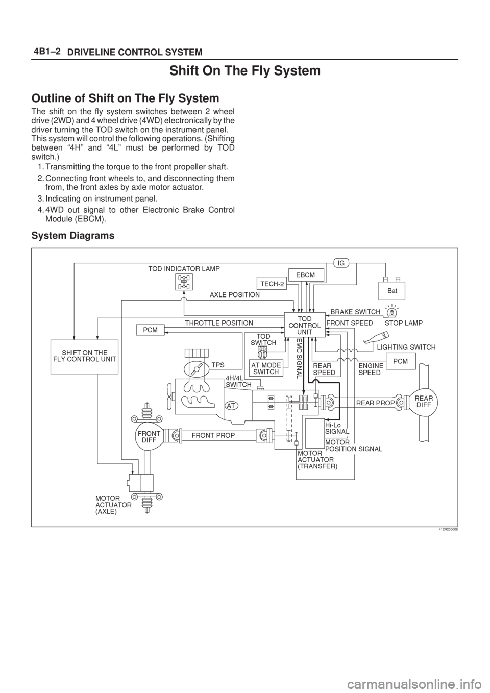
Outline of Shift on The Fly System
The shift on the fly system switches between 2 wheel
drive (2WD) and 4 wheel drive (4WD) electronically by the
driver turning the TOD switch on the instrument panel.
This system will control the following operations. (Shifting
between ª4Hº and ª4Lº must be performed by TOD
switch.)
1. Transmitting the torque to the front propeller shaft.
2. Connecting front wheels to, and disconnecting them
from, the front axles by axle motor actuator.
3. Indicating on instrument panel.
4. 4WD out signal to other Electronic Brake Control
Module (EBCM).
System Diagrams
412R200008
Page 375 of 2100
4B1±3
DRIVELINE CONTROL SYSTEM
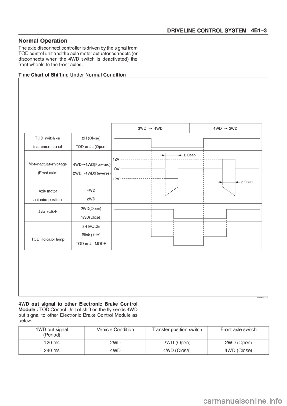
Normal Operation
The axle disconnect controller is driven by the signal from
TOD control unit and the axle motor actuator connects (or
disconnects when the 4WD switch is deactivated) the
front wheels to the front axles.
Time Chart of Shifting Under Normal Condition
F04R200002
4WD out signal to other Electronic Brake Control
Module : TOD Control Unit of shift on the fly sends 4WD
out signal to other Electronic Brake Control Module as
below.
4WD out signal
(Period)
Vehicle ConditionTransfer position switchFront axle switch
120 ms2WD2WD (Open)2WD (Open)
240 ms4WD4WD (Close)4WD (Close)
Page 376 of 2100
4B1±4
DRIVELINE CONTROL SYSTEM
Functions of Indicator Lamp
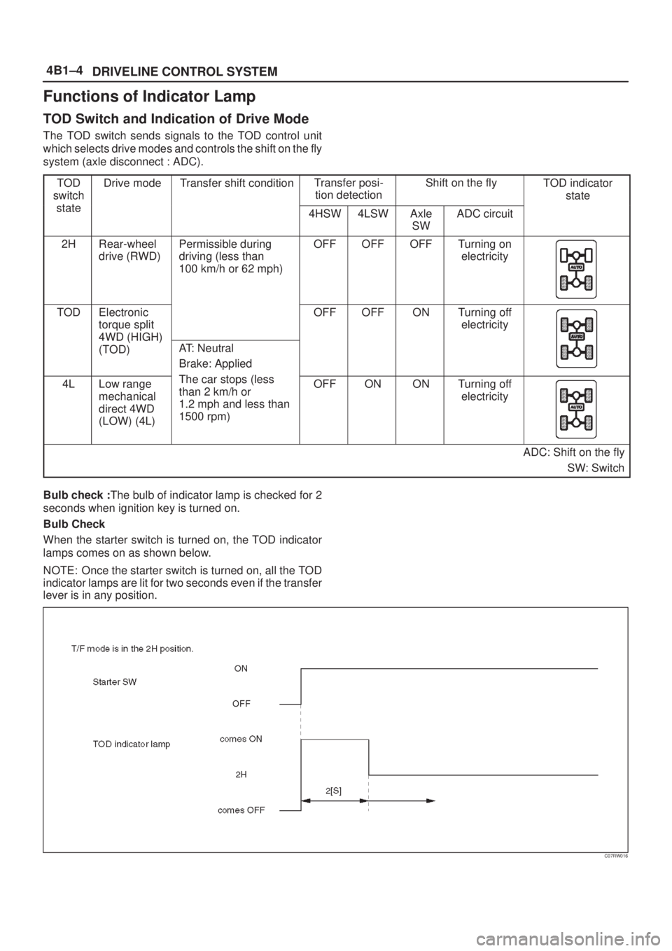
TOD Switch and Indication of Drive Mode
The TOD switch sends signals to the TOD control unit
which selects drive modes and controls the shift on the fly
system (axle disconnect : ADC).
TOD
switch
tt
Drive modeTransfer shift conditionTransfer posi-
tion detectionShift on the flyTOD indicator
state
state4HSW4LSWAxle
SWADC circuit
2HRear-wheel
drive (RWD)Permissible during
driving (less than
100 km/h or 62 mph)OFFOFFOFFTurning on
electricity
TODElectronic
torque split
4WD (HIGH)
OFFOFFONTurning off
electricity
4WD (HIGH)
(TOD)AT: Neutral
Brake: Applied
Th t (l4LLow range
mechanical
direct 4WD
(LOW) (4L)The car stops (less
than 2 km/h or
1.2 mph and less than
1500 rpm)OFFONONTurning off
electricity
ADC: Shift on the fly
SW: Switch
Bulb check :The bulb of indicator lamp is checked for 2
seconds when ignition key is turned on.
Bulb Check
When the starter switch is turned on, the TOD indicator
lamps comes on as shown below.
NOTE: Once the starter switch is turned on, all the TOD
indicator lamps are lit for two seconds even if the transfer
lever is in any position.
C07RW016
Page 377 of 2100

4B1±5
DRIVELINE CONTROL SYSTEM
Shift On The Fly Electrical Equipment
Axle Shaft Connection and Disconnection
412R200006
Actuator Assembly
412RY00004
Axle Disconnect Controller
828RY00009
Page 378 of 2100
4B1±6
DRIVELINE CONTROL SYSTEM
828RY00010
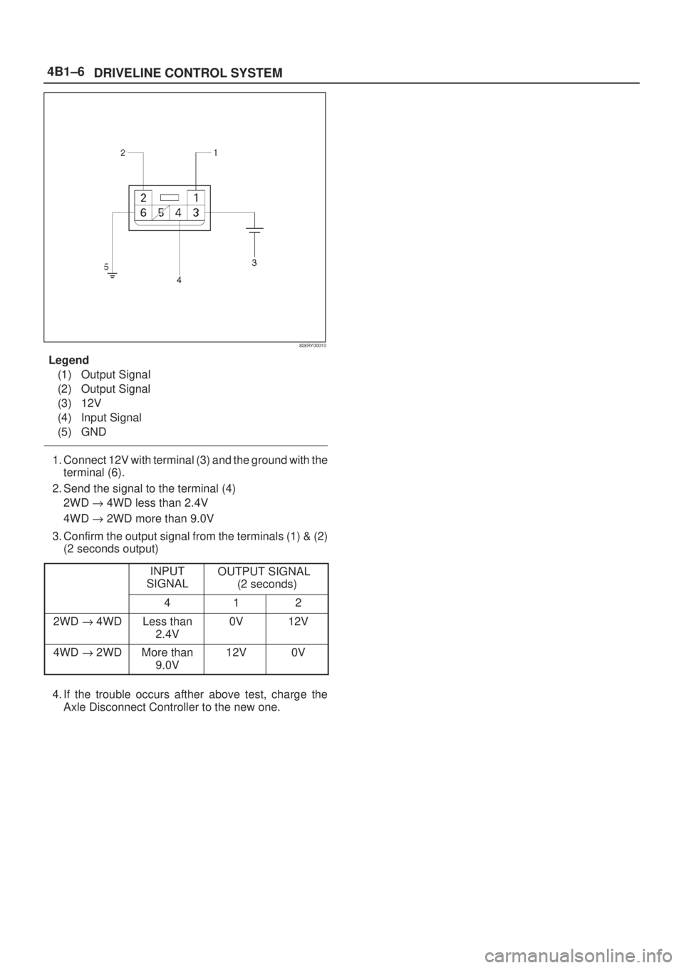
Legend
(1) Output Signal
(2) Output Signal
(3) 12V
(4) Input Signal
(5) GND
1. Connect 12V with terminal (3) and the ground with the
terminal (6).
2. Send the signal to the terminal (4)
2WD " 4WD less than 2.4V
4WD " 2WD more than 9.0V
3. Confirm the output signal from the terminals (1) & (2)
(2 seconds output)
INPUT
SIGNALOUTPUT SIGNAL
(2 seconds)
412
2WD " 4WDLess than
2.4V0V12V
4WD " 2WDMore than
9.0V12V0V
4. If the trouble occurs afther above test, charge the
Axle Disconnect Controller to the new one.
Page 379 of 2100

4B1±7
DRIVELINE CONTROL SYSTEM
Shift On The Fly Controller
Shift On The Fly Controller and Associated Parts
828RY00003
Legend
(1) Nut(2) SOF Controller
(3) Connector
Removal
1. Disconnect the battery ground cable.
2. Remove the front console assembly.
Refer to
Consoles in Body and Accessories section.
3. Disconnect the connector from the controller.
4. Remove the nut.
5. Remove the controller.
Installation
To install, follow the removal steps in the reverse order,
noting the following points.
Torque: Nut (1) 8 N´m (69 Ib in)
Page 380 of 2100
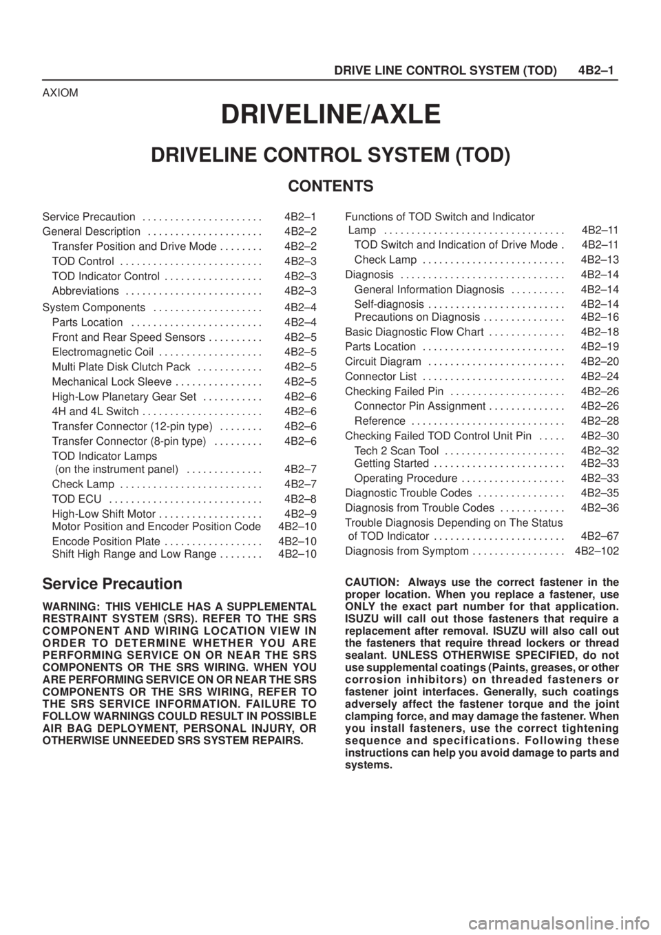
4B2±1
DRIVE LINE CONTROL SYSTEM (TOD)
AXIOM
DRIVELINE/AXLE
DRIVELINE CONTROL SYSTEM (TOD)
CONTENTS
Service Precaution 4B2±1. . . . . . . . . . . . . . . . . . . . . .
General Description 4B2±2. . . . . . . . . . . . . . . . . . . . .
Transfer Position and Drive Mode 4B2±2. . . . . . . .
TOD Control 4B2±3. . . . . . . . . . . . . . . . . . . . . . . . . .
TOD Indicator Control 4B2±3. . . . . . . . . . . . . . . . . .
Abbreviations 4B2±3. . . . . . . . . . . . . . . . . . . . . . . . .
System Components 4B2±4. . . . . . . . . . . . . . . . . . . .
Parts Location 4B2±4. . . . . . . . . . . . . . . . . . . . . . . .
Front and Rear Speed Sensors 4B2±5. . . . . . . . . .
Electromagnetic Coil 4B2±5. . . . . . . . . . . . . . . . . . .
Multi Plate Disk Clutch Pack 4B2±5. . . . . . . . . . . .
Mechanical Lock Sleeve 4B2±5. . . . . . . . . . . . . . . .
High-Low Planetary Gear Set 4B2±6. . . . . . . . . . .
4H and 4L Switch 4B2±6. . . . . . . . . . . . . . . . . . . . . .
Transfer Connector (12-pin type) 4B2±6. . . . . . . .
Transfer Connector (8-pin type) 4B2±6. . . . . . . . .
TOD Indicator Lamps
(on the instrument panel) 4B2±7. . . . . . . . . . . . . .
Check Lamp 4B2±7. . . . . . . . . . . . . . . . . . . . . . . . . .
TOD ECU 4B2±8. . . . . . . . . . . . . . . . . . . . . . . . . . . .
High-Low Shift Motor 4B2±9. . . . . . . . . . . . . . . . . . .
Motor Position and Encoder Position Code 4B2±10
Encode Position Plate 4B2±10. . . . . . . . . . . . . . . . . .
Shift High Range and Low Range 4B2±10. . . . . . . . Functions of TOD Switch and Indicator
Lamp 4B2±11. . . . . . . . . . . . . . . . . . . . . . . . . . . . . . . . .
TOD Switch and Indication of Drive Mode 4B2±11.
Check Lamp 4B2±13. . . . . . . . . . . . . . . . . . . . . . . . . .
Diagnosis 4B2±14. . . . . . . . . . . . . . . . . . . . . . . . . . . . . .
General Information Diagnosis 4B2±14. . . . . . . . . .
Self-diagnosis 4B2±14. . . . . . . . . . . . . . . . . . . . . . . . .
Precautions on Diagnosis 4B2±16. . . . . . . . . . . . . . .
Basic Diagnostic Flow Chart 4B2±18. . . . . . . . . . . . . .
Parts Location 4B2±19. . . . . . . . . . . . . . . . . . . . . . . . . .
Circuit Diagram 4B2±20. . . . . . . . . . . . . . . . . . . . . . . . .
Connector List 4B2±24. . . . . . . . . . . . . . . . . . . . . . . . . .
Checking Failed Pin 4B2±26. . . . . . . . . . . . . . . . . . . . .
Connector Pin Assignment 4B2±26. . . . . . . . . . . . . .
Reference 4B2±28. . . . . . . . . . . . . . . . . . . . . . . . . . . .
Checking Failed TOD Control Unit Pin 4B2±30. . . . .
Tech 2 Scan Tool 4B2±32. . . . . . . . . . . . . . . . . . . . . .
Getting Started 4B2±33. . . . . . . . . . . . . . . . . . . . . . . .
Operating Procedure 4B2±33. . . . . . . . . . . . . . . . . . .
Diagnostic Trouble Codes 4B2±35. . . . . . . . . . . . . . . .
Diagnosis from Trouble Codes 4B2±36. . . . . . . . . . . .
Trouble Diagnosis Depending on The Status
of TOD Indicator 4B2±67. . . . . . . . . . . . . . . . . . . . . . . .
Diagnosis from Symptom 4B2±102. . . . . . . . . . . . . . . . .
Service Precaution
WARNING: THIS VEHICLE HAS A SUPPLEMENTAL
RESTRAINT SYSTEM (SRS). REFER TO THE SRS
COMPONENT AND WIRING LOCATION VIEW IN
ORDER TO DETERMINE WHETHER YOU ARE
PERFORMING SERVICE ON OR NEAR THE SRS
COMPONENTS OR THE SRS WIRING. WHEN YOU
ARE PERFORMING SERVICE ON OR NEAR THE SRS
COMPONENTS OR THE SRS WIRING, REFER TO
THE SRS SERVICE INFORMATION. FAILURE TO
FOLLOW WARNINGS COULD RESULT IN POSSIBLE
AIR BAG DEPLOYMENT, PERSONAL INJURY, OR
OTHERWISE UNNEEDED SRS SYSTEM REPAIRS.CAUTION: Always use the correct fastener in the
proper location. When you replace a fastener, use
ONLY the exact part number for that application.
ISUZU will call out those fasteners that require a
replacement after removal. ISUZU will also call out
the fasteners that require thread lockers or thread
sealant. UNLESS OTHERWISE SPECIFIED, do not
use supplemental coatings (Paints, greases, or other
corrosion inhibitors) on threaded fasteners or
fastener joint interfaces. Generally, such coatings
adversely affect the fastener torque and the joint
clamping force, and may damage the fastener. When
you install fasteners, use the correct tightening
sequence and specifications. Following these
instructions can help you avoid damage to parts and
systems.