steering wheel ISUZU AXIOM 2002 Service Owner's Guide
[x] Cancel search | Manufacturer: ISUZU, Model Year: 2002, Model line: AXIOM, Model: ISUZU AXIOM 2002Pages: 2100, PDF Size: 19.35 MB
Page 195 of 2100
2A±44
POWER±ASSISTED STEERING SYSTEM
Steering Column
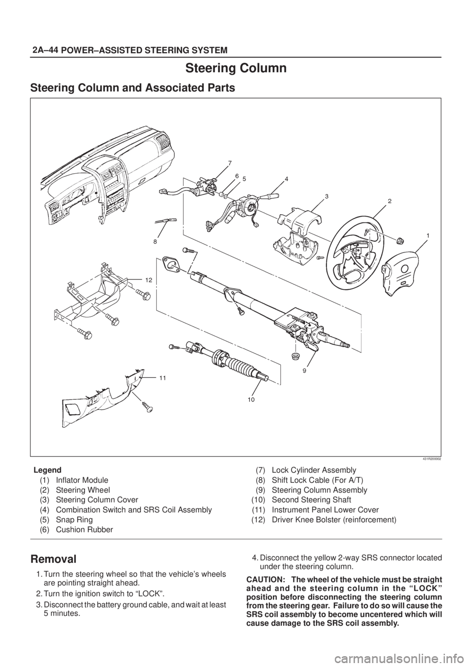
Steering Column and Associated Parts
431R200002
Legend
(1) Inflator Module
(2) Steering Wheel
(3) Steering Column Cover
(4) Combination Switch and SRS Coil Assembly
(5) Snap Ring
(6) Cushion Rubber(7) Lock Cylinder Assembly
(8) Shift Lock Cable (For A/T)
(9) Steering Column Assembly
(10) Second Steering Shaft
(11) Instrument Panel Lower Cover
(12) Driver Knee Bolster (reinforcement)
Removal
1. Turn the steering wheel so that the vehicle's wheels
are pointing straight ahead.
2. Turn the ignition switch to ªLOCKº.
3. Disconnect the battery ground cable, and wait at least
5 minutes.4. Disconnect the yellow 2-way SRS connector located
under the steering column.
CAUTION: The wheel of the vehicle must be straight
ahead and the steering column in the ªLOCKº
position before disconnecting the steering column
from the steering gear. Failure to do so will cause the
SRS coil assembly to become uncentered which will
cause damage to the SRS coil assembly.
Page 196 of 2100
POWER±ASSISTED STEERING SYSTEM2A±45
5. Remove the engine hood opening lever, then remove
instrument panel lower cover.
6. Remove driver knee bolster (reinforcement).
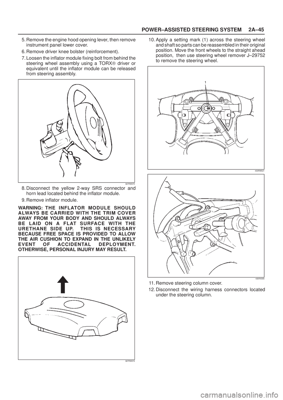
7. Loosen the inflator module fixing bolt from behind the
steering wheel assembly using a TORX) driver or
equivalent until the inflator module can be released
from steering assembly.
827RW070
8. Disconnect the yellow 2-way SRS connector and
horn lead located behind the inflator module.
9. Remove inflator module.
WARNING: T H E I N F L AT O R M O D U L E S H O U L D
ALWAYS BE CARRIED WITH THE TRIM COVER
AWAY FROM YOUR BODY AND SHOULD ALWAYS
BE LAID ON A FLAT SURFACE WITH THE
URETHANE SIDE UP. THIS IS NECESSARY
BECAUSE FREE SPACE IS PROVIDED TO ALLOW
THE AIR CUSHION TO EXPAND IN THE UNLIKELY
EVENT OF ACCIDENTAL DEPLOYMENT.
OTHERWISE, PERSONAL INJURY MAY RESULT.
827RW072
10. Apply a setting mark (1) across the steering wheel
and shaft so parts can be reassembled in their original
position. Move the front wheels to the straight ahead
position, then use steering wheel remover J±29752
to remove the steering wheel.
430RW021
430RX005
11. Remove steering column cover.
12. Disconnect the wiring harness connectors located
under the steering column.
Page 199 of 2100
2A±48
POWER±ASSISTED STEERING SYSTEM
Tilt Mechanism
Tilt mechanism should moves smoothly.
While locked the tilt mechanism, be sure the steering
column latch securely by pushing the steering wheel
upward and downward.
Installation
1. Pass through the steering column assembly to the
dash panel hole.
Temporary tightening the steering column bolt(cross
beam).
2. Tighten the steering column bolts(dash panel) to the
specified torque.
Torque: 20 N´m (14 lb ft)
3. Tighten the steering column nuts (cross beam) to the
specified torque.
Torque: 17 N´m (12 lb ft)
4. Install the universal joint assembly to the transfer
gear assembly align the setting marks made at
removal.
Then tighten the universal joint bolt.
Torque: 31 N´m (23 lb ft)
5. Install the second steering shaft to the universal joint
assembly, then tighten the universal joint bolt to the
specified torque.
Torque: 31 N´m (23 lb ft)
6. Install lock cylinder assembly.
7. Install shift lock cable (For A/T).
8. Install cushion rubber.
9. Install snap ring.
10. Install combination switch and SRS coil assembly.
After installation of combination switch assembly,
connect the combination switch wiring harness
connector and the SRS 2-way connector located
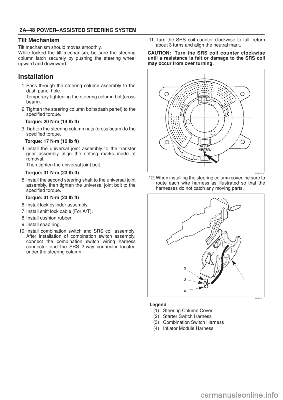
under the steering column.11. Turn the SRS coil counter clockwise to full, return
about 3 turns and align the neutral mark.
CAUTION: Turn the SRS coil counter clockwise
until a resistance is felt or damage to the SRS coil
may occur from over turning.
825RW016
12. When installing the steering column cover, be sure to
route each wire harness as illustrated so that the
harnesses do not catch any moving parts.
825RW017
Legend
(1) Steering Column Cover
(2) Starter Switch Harness
(3) Combination Switch Harness
(4) Inflator Module Harness
Page 200 of 2100
POWER±ASSISTED STEERING SYSTEM2A±49
13. Install steering wheel and align the setting marks
made when removing.
CAUTION: Never apply force to the steering wheel
shaft using a hammer or other impact tools in an
attempt to remove the steering wheel. The steering
shaft is designed as an energy absorbing unit.
14. Tighten the steering wheel fixing nut to the specified
torque.
Torque: 34 N´m (25 lb ft)
15. Support the module and carefully connect the module
connector and horn lead, then install inflator module.
NOTE: Pass the lead wire through the tabs on the plastic
cover (wire protector) of inflator to prevent lead wire from
being pinched.
16. Tighten bolts to specified torque.
Torque: 9 N´m (78 lb in)
17. Install driver knee bolster (reinforcement).
18. Install instrument panel lower cover.
19. Install the engine hood opening lever.
20. Connect the yellow 2-way SRS connector and horn
lead located under the steering column.
21. Connect the battery ground cable.
System Inspection
Turn the ignition switch ªONº and observe if the warning
lamp flashes 7 times. If the warning lamp does not
operate correctly, refer to
Restraints section.
Page 201 of 2100
2A±50
POWER±ASSISTED STEERING SYSTEM
Supplemental Restraint System Steering Wheel & Column and
Associated Parts
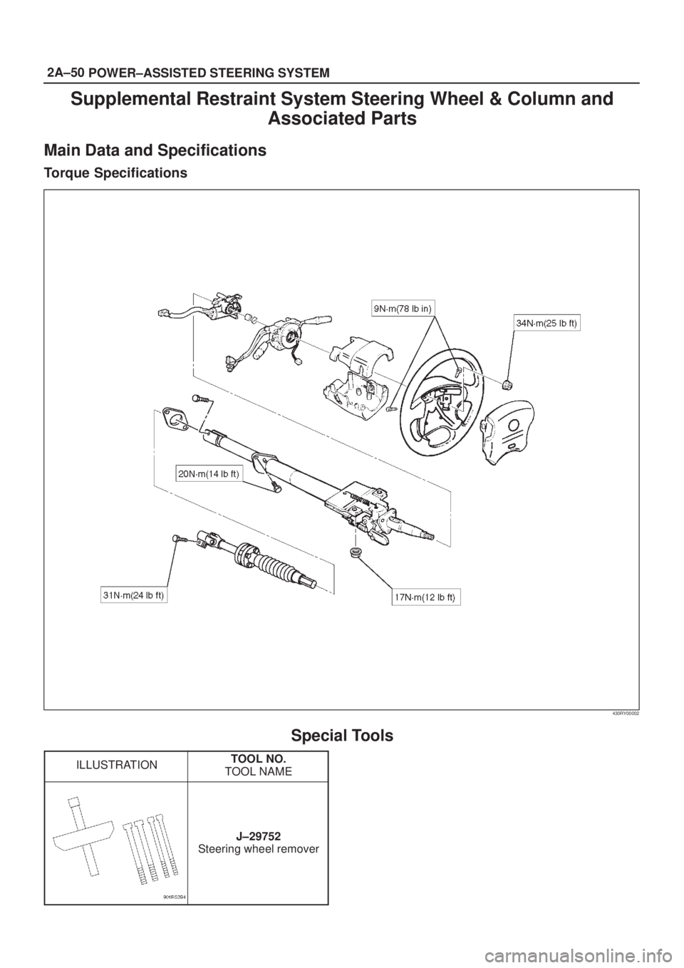
Main Data and Specifications
Torque Specifications
430RY00002
Special Tools
ILLUSTRATIONTOOL NO.
TOOL NAME
J±29752
Steering wheel remover
Page 203 of 2100
3C±2FRONT SUSPENSION
General Description
The front suspension is designed to allow each wheel to
compensate for changes in the road surface level without
greatly affecting the opposite wheel. Each wheel is
independently connected to the frame by a steering
knuckle, ball joint assemblies, and upper and lower
control arms. The front wheels are held in proper
relationship to each other by two tie-rods which are
connected to steering arms on the knuckles, and to a
steering unit.
All models have a front suspension system consisting of
control arms, stabilizer bar, shock absorber and a torsion
bar. The front end of the torsion bar is attached to the
lower control arm. The rear of the torsion bar is mounted
into a height control arm at the crossmember. Vehicle trim
height is controlled by adjusting this arm.
Shock absorbers are mounted between the brackets on
the frame and the lower control arms. The lower portion ofeach shock absorber is attached to the lower control arm.
The upper portion of each shock absorber extends
through a frame bracket and is secured with two rubber
bushings, two retainers and a nut.
Ball joint assemblies are bolted to the outer end of the
upper and lower control arm and are attached to the
steering knuckle.
The inner ends of the upper control arm have pressed in
bushings. Bolts, passing through the bushing, attach the
control arm to the frame. The inner ends of the lower
control arm are attached to the frame by bolts passing
through the bushings.
Side roll of the front suspension is controlled by a spring
steel stabilizer bar. It is mounted in rubber bushings,
which are held to the frame by brackets. The ends of the
stabilizer bar are connected to the lower control arms by
links.
Diagnosis
ConditionPossible causeCorrection
Vehicle PullsMismatched or uneven tires.Replace tire.
Tires not adequately inflated.Adjust tire pressure.
Broken or sagging springs.Replace spring.
Radial tire lateral force.Replace tire.
Improper wheel alignment.Adjust wheel alignment.
Brake dragging in one wheel.Repair brake.
Loose, bent or broken front or rear
suspension parts.Tighten or replace the appropriate
suspension part(s).
Faulty shock absorbers.Replace shock absorber.
Parts in power steering valve
defective.Replace power steering unit.
Abnormal or Excessive Tire WearSagging or broken spring.Replace spring.
Tire out of balance.Balance or replace tire.
Improper wheel alignment.Check front end alignment.
Faulty shock absorber.Replace shock absorber.
Hard driving.Replace tire.
Overloaded vehicle.Replace tire and reduce load.
Tires not rotated periodically.Replace or rotate tire.
Worn or loose road wheel bearings.Replace wheel bearing.
Wobbly wheel or tires.Replace wheel or tire.
Tires not adequately inflated.Adjust the pressure.
Wheel HopBlister or bump on tire.Replace tire.
Improper shock absorber operation.Replace shock absorber.
Page 204 of 2100

FRONT SUSPENSION3C±3
Condition CorrectionPossible cause
Shimmy, Shake or VibrationTire or wheel out of balance.Balance wheels or replace tire/or
wheel.
Loose wheel bearings.Replace wheel bearing.
Worn steering linkage ball joints.Replace ball joints.
Worn upper or lower end ball joints.Replace ball joints.
Excessive wheel runout.Repair or replace wheel and/or tire.
Blister or bump on tire.Replace tire.
Excessive loaded radial runout of
tire/wheel assembly.Replace tire or wheel.
Improper wheel alignment.Check wheel alignment.
Loose or worn steering linkage.Tighten or replace steering linkage.
Loose steering unit.Tighten steering unit.
Tires not adequately inflated.Adjust tire pressure.
Loose, bent or broken front or rear
suspension parts.Tighten or replace the appropriate
suspension parts.
Faulty shock absorber.Replace shock absorber.
Hub bearing preload misadjustment.Adjust preload.
Parts in power steering valve
defective.Replace power steering unit.
Hard SteeringBind in steering linkage ball studs,
upper or lower ball joint.Replace ball joint.
Improper wheel alignment.Check wheel alignment.
Tire not adequately inflated.Inflate tires to proper pressure.
Bind in steering column or shaft.Repair or replace.
Improper power steering system
operation.Repair or replace. Refer to Steering
section.
Too Much Play In SteeringWheel bearings worn.Replace wheel bearings.
Loose steering unit or linkage.Retighten or repair.
Worn or loose steering shaft
universal joint.Retighten or replace steering shaft.
Worn steering linkage ball joints.Replace ball joints.
Worn upper or lower end ball joints.Replace ball joints.
Poor Steering Wheel ReturnabilityBind in steering linkage ball joints.Replace ball joints.
Bind in upper or lower ball joints.Replace ball joints.
Bind in steering column and shaft.Repair or replace.
Bind in steering gear.Check and repair steering gear.
Improper wheel alignment.Adjust wheel alignment.
Tires not adequately inflated.Adjust pressure.
Loose steering wheel nut.Retighten.
Worn wheel bearing.Replace.
Page 205 of 2100

3C±4FRONT SUSPENSION
Condition CorrectionPossible cause
Abnormal NoiseWorn, sticky or loose upper or lower
ball joint, steering linkage ball joints
or drive axle joints.Replace.
Faulty shock absorbers.Replace.
Worn upper or lower control arm
bushing.Replace.
Loose stabilizer bar.Retighten bolts or replace bushings.
Loose wheel nuts.Tighten nuts. Check for elongated
wheel nut holes. Replace wheel if
required.
Loose suspension bolts or nuts.Retighten suspension bolts or nuts.
Broken or otherwise damaged wheel
bearings.Replace wheel bearing.
Broken suspension springs. Replace spring.
Loose steering unit. Retighten mounting bolt.
Faulty steering unit.Replace steering unit.
Wandering or Poor Steering StabilityMismatched or unevenly worn tires.Replace tire or inflate tires to proper
pressure.
Loose steering linkage ball joints.Replace ball joints.
Faulty shock absorbers.Replace shock absorber.
Loose stabilizer bar.Tighten or replace stabilizer bar or
bushings.
Broken or sagging springs.Replace spring (pairs).
Improper wheel alignment.Adjust wheel alignment.
Erratic Steering When BrakingWorn wheel bearings.Replace wheel bearings.
Broken or sagging springs.Replace spring (pairs).
Leaking caliper.Repair or replace caliper.
Warped discs.Replace brake disc.
Badly worn brake pads.Replace brake pads.
Tires are inflated unequally.Inflate tires to proper pressure.
Low or Uneven Trim HeightBroken or sagging springs.Replace springs (In pairs).
Vehicle overloaded.Reduce load.
Incorrect springs.Adjust or replace torsion bar.
Suspension BottomsVehicle overloaded. Reduce load.
Faulty shock absorber.Replace shock absorber.
Incorrect, broken or sagging springs.Replace springs.
Body LeansLoose stabilizer bar.Tighten stabilizer bar bolts or replace
bushings.
Faulty shock absorber, struts or
mounting.Replace shock absorber.
Broken or sagging springs.Replace springs (In pairs).
Vehicle overloaded.Reduce load.
Cupped TiresWorn wheel bearings.Replace wheel bearing.
Excessive tire or wheel run out.Replace tire or wheel.
Worn ball joints.Replace ball joints.
Tire out of balance.Adjust tire balance.
Page 211 of 2100

3C±10FRONT SUSPENSION
Knuckle
Knuckle and Associated Parts
410RW006
Legend
(1) Torsion Bar
(2) Lower Ball Joint, Nut and Cotter Pin
(3) Back Plate
(4) Knuckle Assembly
(5) Knuckle(6) Needle Bearing (4WD MODEL)
(7) Thrust Washer (4WD MODEL)
(8) Oil Seal (4WD MODEL)
(9) Upper Ball Joint, Nut and Cotter Pin
(10) Wheel Speed Sensor
Removal
1. Raise the vehicle and support the frame with suitable
safety stands.
2. Remove wheel and tire assembly. Refer to
Wheel in
this section.
3. Remove the brake caliper. Refer to Disc Brakes in
Brake section.
4. Remove the hub assembly. Refer to Front Hub and
Disk in this section.
5. Remove tie±rod end from the knuckle. Refer to Power
Steering Unit in Steering section.
6. Remove the speed sensor from the knuckle.
7. Loosen torsion bar by height control arm adjust bolt,
then remove torsion bar. Refer to
Torsion Bar in this
section.
8. Remove wheel speed sensor.
Page 213 of 2100

3C±12FRONT SUSPENSION
2. Apply multipurpose type grease to the thrust washer,
and install washer with chamfered side facing knuckle
(Except 2WD model).
3. Use a new oil seal, and apply multipurpose type
grease to the area surrounded by the lip (approx. 2 g).
Then use installer J±36837 and J±8092 to install oil
seal. After fitting the oil seal to the installer, drive it to
the knuckle using a hammer or bench press until the
tool front face contacts with the thrust washer (Except
2WD model).
901RW167
4. Install knuckle assembly.
5. Install upper ball joint and tighten the nut to the
specified torque, with just enough additional torque to
align cotter pin holes. Install new cotter pin.
Torque: 98 N´m (72 lb ft)
6. Install lower ball joint and tighten the nut to the
specified torque, with just enough additional torque to
align cotter pin holes. Install new cotter pin.
Torque: 147 N´m (108 lb ft)
7. Install back plate.
8. Install wheel speed sensor.
9. Install torsion bar, refer to
Torsion Bar in this section.
NOTE: A d j u s t t h e t r i m h e ight. Refer to Front End
Alignment Inspection and Adjustment in Steering.