lock ISUZU KB P190 2007 Workshop Repair Manual
[x] Cancel search | Manufacturer: ISUZU, Model Year: 2007, Model line: KB P190, Model: ISUZU KB P190 2007Pages: 6020, PDF Size: 70.23 MB
Page 4770 of 6020
Manual Transmission (MUX) 7B1-51
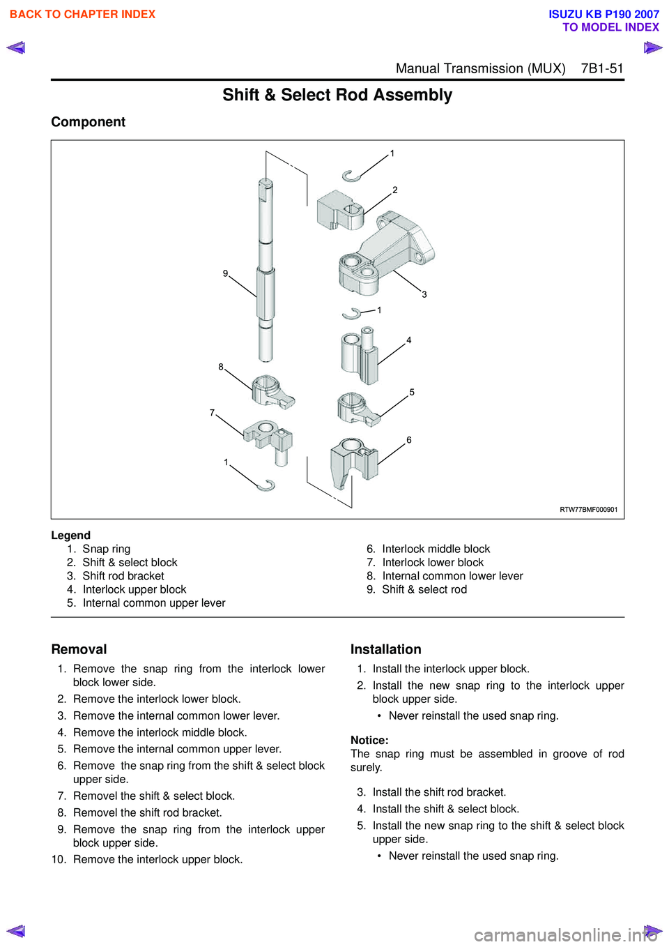
Shift & Select Rod Assembly
Component
Legend1. Snap ring
2. Shift & select block
3. Shift rod bracket
4. Interlock upper block
5. Internal common upper lever 6. Interlock middle block
7. Interlock lower block
8. Internal common lower lever
9. Shift & select rod
Removal
1. Remove the snap ring from the interlock lower block lower side.
2. Remove the interlock lower block.
3. Remove the internal common lower lever.
4. Remove the interlock middle block.
5. Remove the internal common upper lever.
6. Remove the snap ring from the shift & select block upper side.
7. Removel the shift & select block.
8. Removel the shift rod bracket.
9. Remove the snap ring from the interlock upper block upper side.
10. Remove the interlock upper block.
Installation
1. Install the interlock upper block.
2. Install the new snap ring to the interlock upper block upper side.
• Never reinstall the used snap ring.
Notice:
The snap ring must be assembled in groove of rod
surely.
3. Install the shift rod bracket.
4. Install the shift & select block.
5. Install the new snap ring to the shift & select block upper side.
• Never reinstall the used snap ring.
RTW77BMF000901
1
2
3
1
4
5
6
1
7
8
9
BACK TO CHAPTER INDEX
TO MODEL INDEX
ISUZU KB P190 2007
Page 4771 of 6020
7B1-52 Manual Transmission (MUX)
Notice:
The snap ring must be assembled in groove of rod
surely.
6. Install the internal common upper lever.
7. Install the interlock middle block.
8. Install the internal common lower lever.
9. Install the interlock lower block.
10. Install the new snap ring to the interlock lower block lower side.
• Never reinstall the used snap ring.
Notice:
The snap ring must be assembled in groove of rod
surely.
BACK TO CHAPTER INDEX
TO MODEL INDEX
ISUZU KB P190 2007
Page 4774 of 6020
Manual Transmission (MUX) 7B1-55
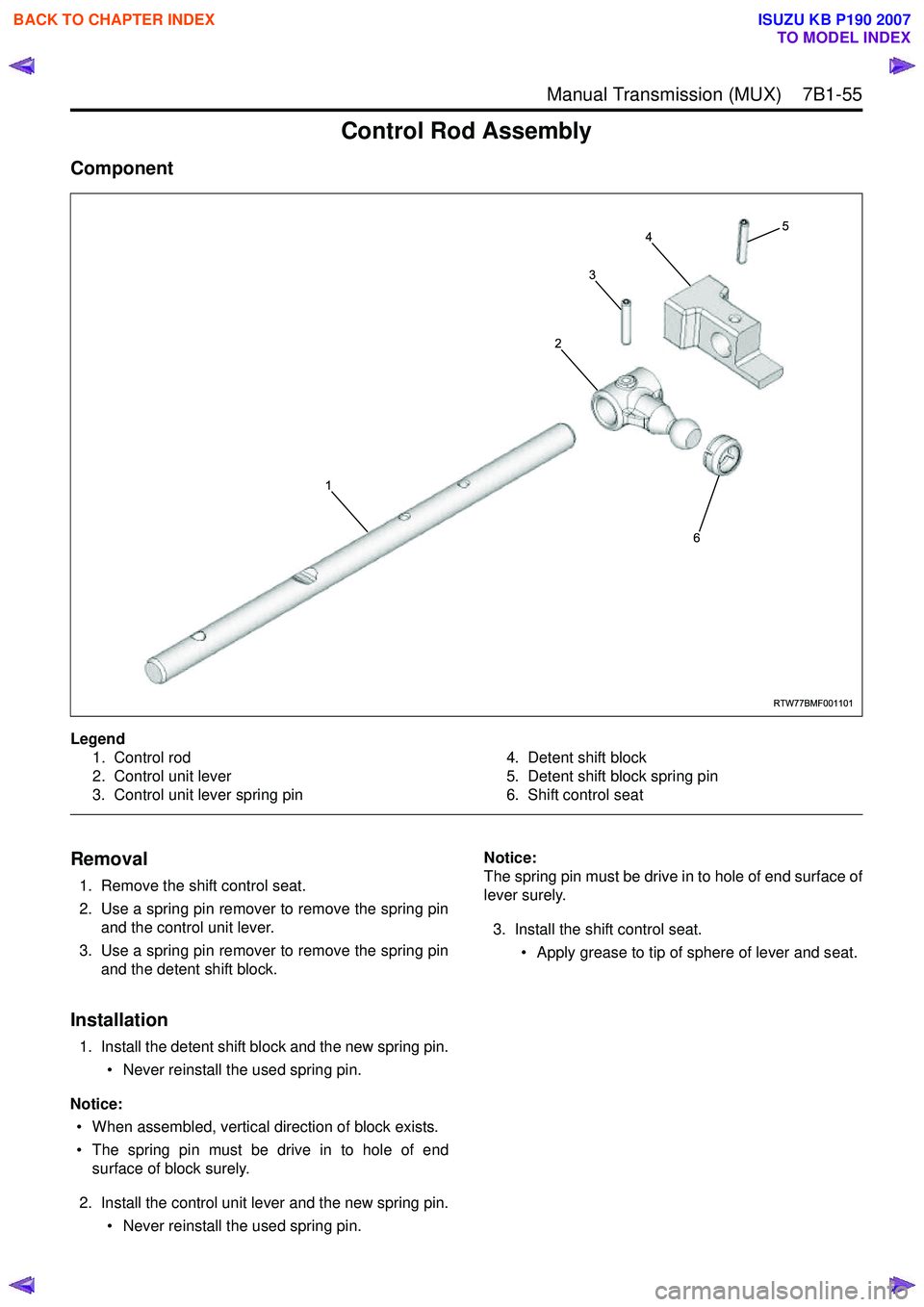
Control Rod Assembly
Component
Legend1. Control rod
2. Control unit lever
3. Control unit lever spring pin 4. Detent shift block
5. Detent shift block spring pin
6. Shift control seat
Removal
1. Remove the shift control seat.
2. Use a spring pin remover to remove the spring pin and the control unit lever.
3. Use a spring pin remover to remove the spring pin and the detent shift block.
Installation
1. Install the detent shift block and the new spring pin.
• Never reinstall the used spring pin.
Notice: • When assembled, vertical direction of block exists.
• The spring pin must be drive in to hole of end surface of block surely.
2. Install the control unit lever and the new spring pin. • Never reinstall the used spring pin. Notice:
The spring pin must be drive in to hole of end surface of
lever surely.
3. Install the shift control seat. • Apply grease to tip of sphere of lever and seat.
RTW77BMF001101
1
2
3
45
6
BACK TO CHAPTER INDEX
TO MODEL INDEX
ISUZU KB P190 2007
Page 4775 of 6020
7B1-56 Manual Transmission (MUX)
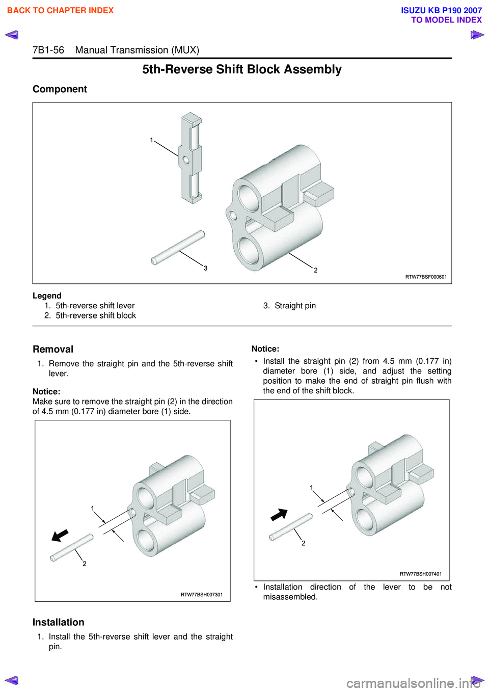
5th-Reverse Shift Block Assembly
Component
Legend1. 5th-reverse shift lever
2. 5th-reverse shift block 3. Straight pin
Removal
1. Remove the straight pin and the 5th-reverse shift
lever.
Notice:
Make sure to remove the straight pin (2) in the direction
of 4.5 mm (0.177 in) diameter bore (1) side.
Installation
1. Install the 5th-reverse shift lever and the straight pin. Notice:
• Install the straight pin (2) from 4.5 mm (0.177 in) diameter bore (1) side, and adjust the setting
position to make the end of straight pin flush with
the end of the shift block.
• Installation direction of the lever to be not misassembled.
RTW77BSF000601
1
23
RTW77BSH007301
1
2
RTW77BSH007401
1
2
BACK TO CHAPTER INDEX
TO MODEL INDEX
ISUZU KB P190 2007
Page 4798 of 6020
7C-20 CLUTCH
SERVICING
Servicing refers to general maintenance procedures to be performed by qualified service personnel.
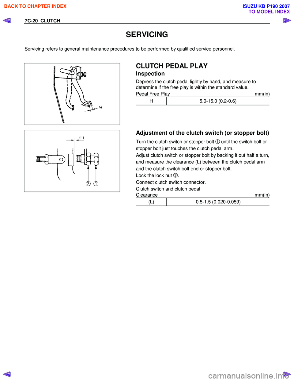
CLUTCH PEDAL PLAY
Inspection
Depress the clutch pedal lightly by hand, and measure to
determine if the free play is within the standard value.
Pedal Free Play mm(in)
H 5.0-15.0 (0.2-0.6)
Adjustment of the clutch switch (or stopper bolt)
Turn the clutch switch or stopper bolt 1 until the switch bolt
or
stopper bolt just touches the clutch pedal arm.
Adjust clutch switch or stopper bolt
by backing it out half a turn,
and measure the clearance (L) between the clutch pedal arm
and the clutch switch bolt end or stopper bolt.
Lock the lock nut
2.
Connect clutch switch connector.
Clutch switch and clutch pedal
Clearance mm(in)
(L) 0.5-1.5 (0.020-0.059)
BACK TO CHAPTER INDEX
TO MODEL INDEX
ISUZU KB P190 2007
Page 4802 of 6020
7C-24 CLUTCH
015RW 053
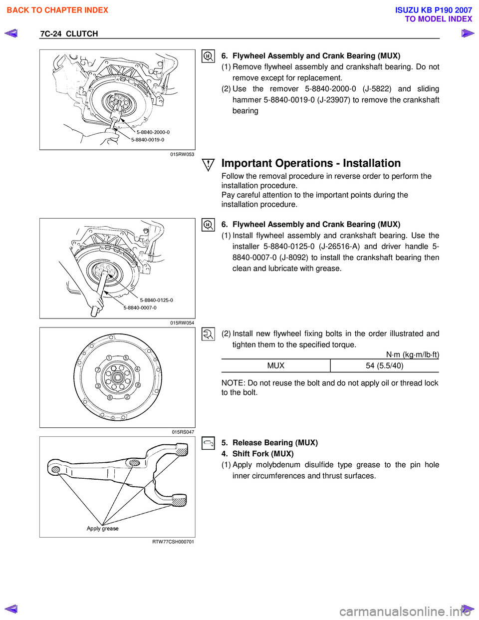
6. Flywheel Assembly and Crank Bearing (MUX)
(1) Remove flywheel assembly and crankshaft bearing. Do not remove except for replacement.
(2) Use the remover 5-8840-2000-0 (J-5822) and sliding hammer 5-8840-0019-0 (J-23907) to remove the crankshaft
bearing
Important Operations - Installation
Follow the removal procedure in reverse order to perform the
installation procedure.
Pay careful attention to the important points during the
installation procedure.
015RW 054
6. Flywheel Assembly and Crank Bearing (MUX)
(1) Install flywheel assembly and crankshaft bearing. Use the installer 5-8840-0125-0 (J-26516-A) and driver handle 5-
8840-0007-0 (J-8092) to install the crankshaft bearing then
clean and lubricate with grease.
015RS047
(2) Install new flywheel fixing bolts in the order illustrated and tighten them to the specified torque. N⋅m (kg ⋅m/lb ⋅ft)
MUX 54 (5.5/40)
NOTE: Do not reuse the bolt and do not apply oil or thread lock
to the bolt.
RTW 77CSH000701
5. Release Bearing (MUX)
4. Shift Fork (MUX)
(1)
Apply molybdenum disulfide type grease to the pin hole
inner circumferences and thrust surfaces.
BACK TO CHAPTER INDEX
TO MODEL INDEX
ISUZU KB P190 2007
Page 4809 of 6020
CLUTCH 7C-31
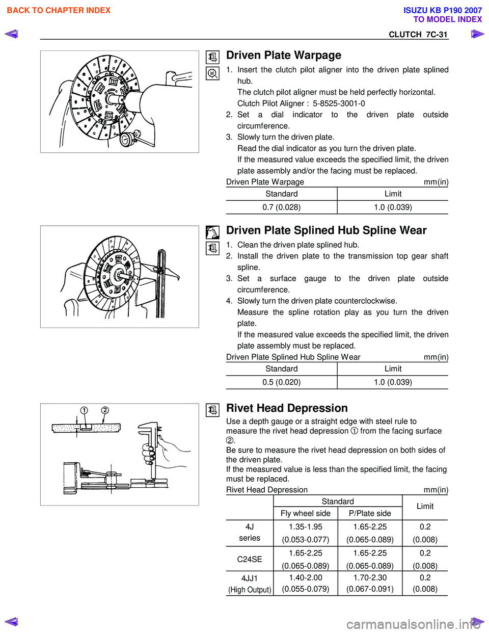
Driven Plate Warpage
1. Insert the clutch pilot aligner into the driven plate splinedhub.
The clutch pilot aligner must be held perfectly horizontal.
Clutch Pilot Aligner : 5-8525-3001-0
2. Set a dial indicator to the driven plate outside circumference.
3. Slowly turn the driven plate.
Read the dial indicator as you turn the driven plate.
If the measured value exceeds the specified limit, the driven plate assembly and/or the facing must be replaced.
Driven Plate W arpage mm(in)
Standard Limit
0.7 (0.028)1.0 (0.039)
Driven Plate Splined Hub Spline Wear
1. Clean the driven plate splined hub.
2. Install the driven plate to the transmission top gear shaft spline.
3. Set a surface gauge to the driven plate outside circumference.
4. Slowly turn the driven plate counterclockwise.
Measure the spline rotation play as you turn the driven plate.
If the measured value exceeds the specified limit, the driven plate assembly must be replaced.
Driven Plate Splined Hub Spline W ear mm(in)
Standard Limit
0.5 (0.020)1.0 (0.039)
Rivet Head Depression
Use a depth gauge or a straight edge with steel rule to
measure the rivet head depression
1 from the facing surface
2.
Be sure to measure the rivet head depression on both sides of
the driven plate.
If the measured value is less than the specified limit, the facing
must be replaced.
Rivet Head Depression mm(in)
Standard
Fly wheel side P/Plate side Limit
4J
series 1.35-1.95
(0.053-0.077) 1.65-2.25
(0.065-0.089) 0.2
(0.008)
C24SE 1.65-2.25
(0.065-0.089) 1.65-2.25
(0.065-0.089) 0.2
(0.008)
4JJ1
(High Output)
1.40-2.00
(0.055-0.079) 1.70-2.30
(0.067-0.091) 0.2
(0.008)
BACK TO CHAPTER INDEX
TO MODEL INDEX
ISUZU KB P190 2007
Page 4811 of 6020
CLUTCH 7C-33
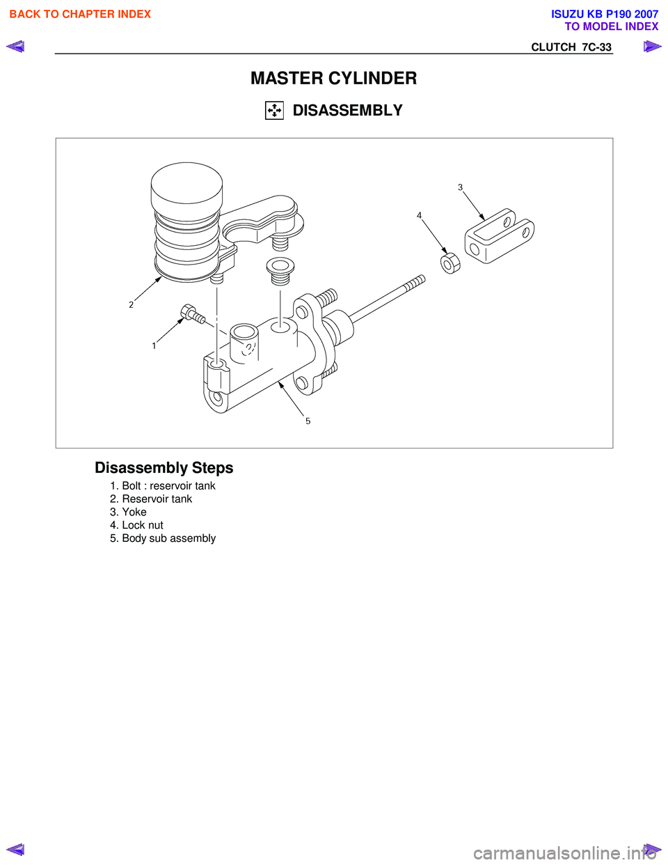
MASTER CYLINDER
DISASSEMBLY
Disassembly Steps
1. Bolt : reservoir tank
2. Reservoir tank
3. Yoke
4. Lock nut
5. Body sub assembly
BACK TO CHAPTER INDEX
TO MODEL INDEX
ISUZU KB P190 2007
Page 4812 of 6020
7C-34 CLUTCH
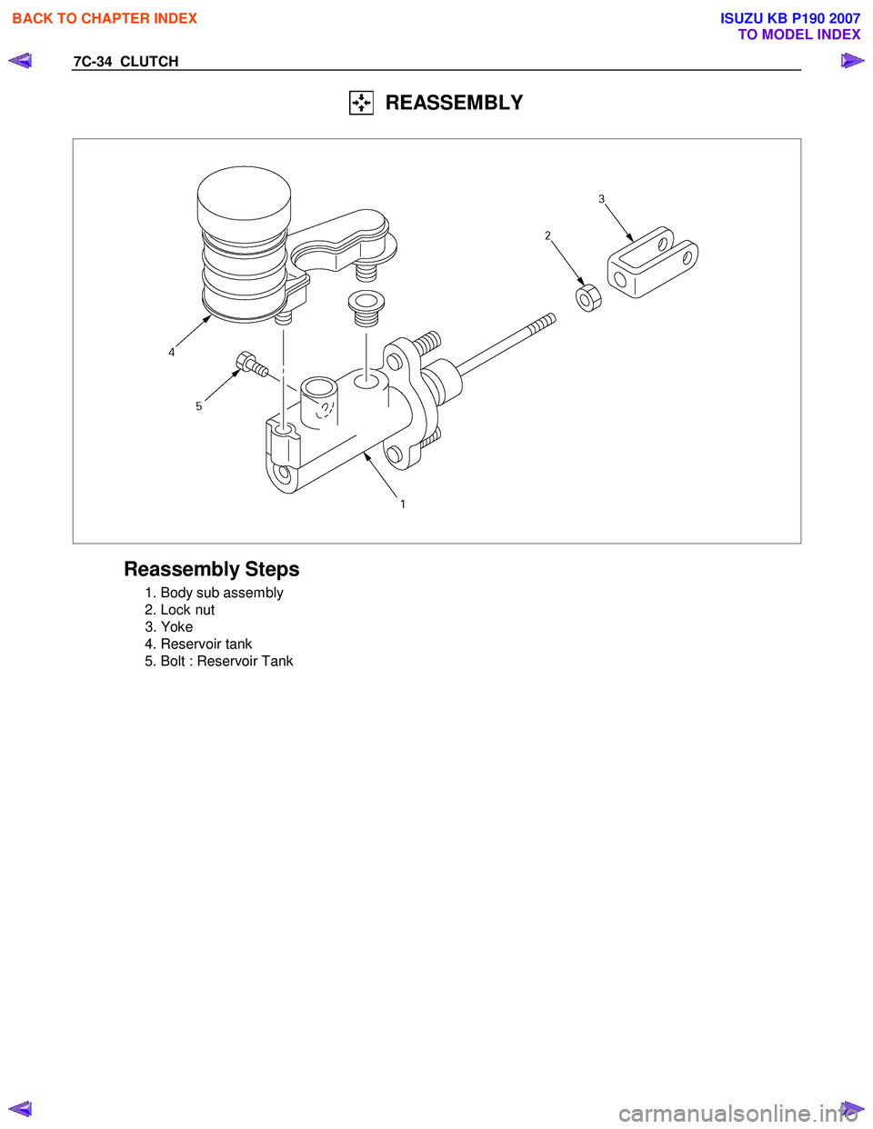
REASSEMBLY
Reassembly Steps
1. Body sub assembly
2. Lock nut
3. Yoke
4. Reservoir tank
5. Bolt : Reservoir Tank
BACK TO CHAPTER INDEX
TO MODEL INDEX
ISUZU KB P190 2007
Page 4832 of 6020
7D-2 TRANSFER CASE
Service Precaution
WARNING: THIS VEHICLE HAS A SUPPLEMENTAL
RESTRAINT SYSTEM (SRS). REFER TO THE SRS
COMPONENT AND WIRING LOCATION VIEW IN
ORDER TO DETERMINE WHETHER YOU ARE
PERFORMING SERVICE ON OR NEAR THE SRS
COMPONENTS OR THE SRS WIRING. WHEN YOU
ARE PERFORMING SERVICE ON OR NEAR THE SRS
COMPONENTS OR THE SRS WIRING, REFER TO
THE SRS SERVICE INFORMATION. FAILURE TO
FOLLOW WARNINGS COULD RESULT IN POSSIBLE
AIR BAG DEPLOYMENT, PERSONAL INJURY, OR
OTHERWISE UNNECESSARY SRS SYSTEM
REPAIRS.
CAUTION: Always use the correct fastener in the
proper location. When you replace a fastener, use
ONLY the exact part number for that application.
ISUZU/GM will call out those fasteners that require a
replacement after removal. ISUZU/GM will also call
out the fasteners that require thread lockers or
thread sealant. UNLESS OTHERWISE SPECIFIED,
do not use supplemental coatings (Paints, greases,
or other corrosion inhibitors) on threaded fasteners
or fastener joint interfaces. Generally, such coatings
adversely affect the fastener torque and the joint
clamping force, and may damage the fastener. When
you install fasteners, use the correct tightening
sequence and specifications. Following these
instructions can help you avoid damage to parts and
systems.
BACK TO CHAPTER INDEX
TO MODEL INDEX
ISUZU KB P190 2007