switch ISUZU TF SERIES 2004 Workshop Manual
[x] Cancel search | Manufacturer: ISUZU, Model Year: 2004, Model line: TF SERIES, Model: ISUZU TF SERIES 2004Pages: 4264, PDF Size: 72.63 MB
Page 1425 of 4264

4JA1/4JH1 ENGINE DRIVEABILITY AND EMISSIONS 6E–53
ECM CONNECTOR PIN ASSIGNMENT & OUTPUT SIGNAL
4JA1-TC ECM CONNECTOR PIN ASSIGNMENT & OUTPUT SIGNA L
View Looking Into ECM Case
Signal or Continuity Tester Position
Pin
No. B/Box
No.Pin Function Wire
ColorKey SW
OffKey SW
OnEngine
IdleEngine
2000rpmECM
Connec-
tionRange (+) (-)
1 1 ECM Gro und BLK Continuity
with
gro und---Discon-
ne ctOhm 1 GND
2 2 ECM Gro und BLK Continuity
with
gro und---Discon-
ne ctOhm 2 GND
3 3 Batte ry Powe r Supply BLU/
REDLess than
1V10-14V Connect DC V 3 GND
25 25 No Conne ctio n - - - - - - - - -
26 26 No Conne ctio n - - - - - - - - -
27 27 Engine Spee d Output
(To Ta cho Me te r)LGN - - Approx.
23Hz by
w a v e fo rm
or approx.
6.3V Approx.
67Hz by
wave form
or approx.
6.8V Co nnect AC V 27 GND
28 28 No Conne ctio n - - - - - - - - -
29 29 No Conne ctio n - - - - - - - - -
30 30 Brake Switch 1 Signal GRN Less than
1VPedal is not stepped on: Less than 1V
Pedal is stepped on: 10-14VCo nnect DC V 30 GND
31 31 Clutch Switch Signal
(MT Only )YEL Less than
1VPedal is not stepped on: 10-14V
Pedal is stepped on: Less than 1VCo nnect DC V 31 GND
32 32 No Conne ctio n - - - - - - - - -
33 33 A/C ON Signa l Re la y GRN/
YELLess than
1VA/C re que st switch is turne d on: 10-
14V
A/C request switch is turned off: Less
than 1VCo nnect DC V 33 GND
34 34 No Conne ctio n - - - - - - - - -
35 35 To Da ta Link Co nnec-
tor No. 6 & Immobi-
lize r Contro l Unit (ICU
B8)YEL--------
36 36 No Conne ctio n - - - - - - - - -
37 37 No Conne ctio n - - - - - - - - -
38 38 Throttle Po sitio n Sen-
so r (TPS) Output Sig-
na lGRN/
ORGLess than
1VLess than 1V Approx.
0.5VCo nnect DC V 38 49
39 39 Key Sw itch Input Sig-
nal Via Engine FuseWHT Less than
1V10-14V Co nnect DC V 39 GND
40 40 No Conne ctio n - - - - - - - - -
Page 1426 of 4264

6E–54 4JA1/4JH1 ENGINE DRIVEABILITY AND EMISSIONS
41 41 A/C Compresso r
Re la yWH T/
GRNLess than
1V10-14V A/C comp. is operated:
L e s s t h a n 1 V
A/C comp. is not oper-
ated: 10 - 14VCo nnect DC V 41 GND
42 42 Che ck Engine La mp GRN/
YELLess than
1VLamp is turned on: Less than 1V
Lamp is turned off: 10-14VCo nnect DC V 42 GND
43 43 Glow La mp ORG/
BLULess than
1VLamp is turned on: Less than 1V
Lamp is turned off: 10-14VCo nnect DC V 43 GND
44 44 No Conne ctio n - - - - - - - - -
45 45 To Da ta Link Co nnec-
to r No . 6BLU Less than
1V10-14V Co nnect DC V 45 GND
46 46 No Conne ctio n - - - - - - - - -
47 47 No Conne ctio n - - - - - - - - -
48 48 No Conne ctio n - - - - - - - - -
49 49 Throttle Po sitio n Sen-
so r (TPS) Gro undBLK/
GRNIdle :
Approx.
0.4K ohm /
WOT:
Approx.
4.0K ohm---Discon-
ne ctOhm 38 49
50 50 No Conne ctio n - - - - - - - - -
51 51 No Conne ctio n - - - - - - - - -
52 52 No Conne ctio n - - - - - - - - -
53 53 No Conne ctio n - - - - - - - - -
54 54 No Conne ctio n - - - - - - - - -
55 55 No Conne ctio n - - - - - - - - -
56 56 No Conne ctio n - - - - - - - - -
57 57 Throttle Po sitio n Sen-
sor (TPS) Po wer Sup-
plyRED/
GRNLess than
1VAppro x . 5V Co nnect DC V 57 49
58 58 ECM Re lay BLU/
BLK10-14V Less than 1V Connect DC V 58 GND
59 59 No Conne ctio n - - - - - - - - -
60 60 No Conne ctio n - - - - - - - - -
61 61 No Conne ctio n - - - - - - - - -
62 62 No Conne ctio n - - - - - - - - -
63 63 ECM Power Supply Less than
1V10-14V - DC V 63 GND
64 64 No Conne ctio n - - - - - - - - -
65 65 Bra ke Switch 2 Signa l WHT/
BLKLess than
1VPedal is not stepped on: 10-14V
Pedal is stepped on: Less than 1VCo nnect DC V 65 GND
66 66 No Conne ctio n - - - - - - - - -
67 67 No Conne ctio n - - - - - - - - -
68 68 Vehicle Spe ed Se n-
so r (VSS)YEL/
GRN- Approx . 14.5Hz by wav e fo rm or
approx. 6.0V at vehicle speed 20km/hCo nnect AC V 68 GND
69 69 Idle Switch GRN/
BLKLess than
1VPedal is not stepped on: Less than 1V
Pedal is stepped on: Approx. 5VCo nnect DC V 69 GND
70 70 No Conne ctio n - - - - - - - - -
71 71 No Conne ctio n - - - - - - - - -
72 72 No Conne ctio n - - - - - - - - -
73 73 No Conne ctio n - - - - - - - - -
74 74 No Conne ctio n - - - - - - - - -Signal or Continuity Tester Position
Pin
No. B/Box
No.Pin Function Wire
ColorKey SW
OffKey SW
OnEngine
IdleEngine
2000rpmECM
Connec-
tionRange (+) (-)
Page 1427 of 4264

4JA1/4JH1 ENGINE DRIVEABILITY AND EMISSIONS 6E–55
75 75 No Conne ctio n - - - - - - - - -
76 76 No Conne ctio n - - - - - - - - -
77 77 No Conne ctio n - - - - - - - - -
78 78 No Conne ctio n - - - - - - - - -
79 79 No Conne ctio n - - - - - - - - -
80 80 No Conne ctio n - - - - - - - - -
81 81 No Conne ctio n - - - - - - - - -
82 82 No Conne ctio n - - - - - - - - -
83 83 Ma ss Air Flo w (MAF)
Se nso r Po wer SupplyWH T/
REDLess than
1VAppro x . 5V Co nnect DC V 83 92
84 84 Intake Air Tempera-
ture (IAT) Sensor Sig-
na lBLK/
BLULess than
1V0 deg. C: Approx. 3.6V / 20 deg. C:
Approx. 2.6V / 40 deg. C: Approx.
1.7V / 60 deg. C: 1.1V / 80 deg. C:
0.7VCo nnect DC V 84 92
85 85 No Conne ctio n - - - - - - - - -
86 86 No Conne ctio n - - - - - - - - -
87 87 Neutral Switch BLK/
WH TLess than
1VIn neutral: Less than 1V
Other than neutral: 10-14VCo nnect DC V 87 GND
88 88 Ma ss Air Flo w (MAF)
Se nso r SignalGRN/
REDLess than
1VAppro x . 1V Appro x .
1.8VApprox.
2.5VCo nnect DC V 88 92
89 89 Engine Coolant Tem-
perature (ECT) Sen-
so r S ig na lGRY Less than
1V0 deg. C: Approx. 4.4V / 20 deg. C:
Approx. 3.8V / 40 deg. C: Approx.
2.9V / 60 deg. C: 2.1V / 80 deg. C:
1.4VCo nnect DC V 89 93
90 90 CKP Se nso r Signal RED - - Appro x .
47Hz by
w a v e fo rm Approx.
134Hz by
wave form
or approx.
1.1VCo nnect AC V 90 98
91 91 CKP Senso r Output
To Pump Co ntrol Unit
(PSG) No.8PNK - - Appro x .
47Hz by
w a v e fo rm Approx.
134Hz by
wave form
or approx.
0.7VCo nnect AC V 91 GND
92 92 Ma ss Air Flo w (MAF)
Se nsor GroundBLK/
REDContinuity
with
gro und- - - Connect Ohm 92 GND
93 93 Engine Coolant Tem-
perature (ECT) Sen-
so r Gro undBLK/
PNKContinuity
with
gro und- - - Connect Ohm 93 GND
94 94 Glo w Relay BLK/
REDLess than
1VGlow system is operated: Less than
1 V
Glow system is not operated: 10 - 14VCo nnect DC V 94 GND
95 95 No Conne ctio n - - - - - - - - -
96 96 No Conne ctio n - - - - - - - - -
97 97 EGR EVRV BLK/
ORG- - Approx. 140Hz by wave
fo rm whe n EVRV is
operated----
98 98 CKP Se nsor Ground WHT Continuity
with
gro und- - - Connect Ohm 98 GND
99 99 CAN (Contro ller Are a
Ne two rk) to PSG No .1BLU--------
100 100 CAN (Contro ller Are a
Ne two rk) to PSG No .2YEL--------Signal or Continuity Tester Position
Pin
No. B/Box
No.Pin Function Wire
ColorKey SW
OffKey SW
OnEngine
IdleEngine
2000rpmECM
Connec-
tionRange (+) (-)
Page 1430 of 4264
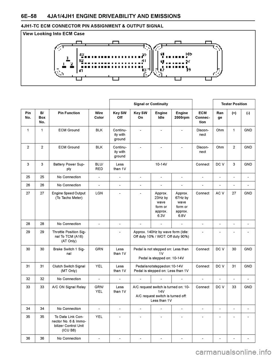
6E–58 4JA1/4JH1 ENGINE DRIVEABILITY AND EMISSIONS
4JH1-TC ECM CONNECTOR PIN ASSIGNMENT & OUTPUT SIGNA L
View Looking Into ECM Case
Signal or Continuity Tester Position
Pin
No. B/
Box
No.Pin Function Wire
ColorKey SW
OffKey SW
OnEngine
IdleEngine
2000rpmECM
Connec-
tionRan
ge(+) (-)
1 1 ECM Gro und BLK Co ntinu-
ity with
ground---Discon-
ne ctOh m 1 GND
2 2 ECM Gro und BLK Co ntinu-
ity with
ground---Discon-
ne ctOh m 2 GND
3 3 Batte ry Powe r Sup-
plyBLU/
REDLe ss
tha n 1V10-14V Co nnect DC V 3 GND
2525No Connection---------
2626No Connection---------
27 27 Engine Spee d Output
(To Ta cho Mete r)LGN - - Approx .
23Hz by
wave
fo rm or
approx.
6.3V Approx.
67Hz by
wave
fo rm or
approx.
6.8V Co nnect AC V 27 GND
2828No Connection---------
29 29 Throttle Positio n Sig-
na l To TCM (A16)
(AT Only )- Appro x . 140Hz by wav e fo rm (Idle:
Off duty 10% / WOT: Off duty 90%)- ---
30 30 Bra ke Switch 1 Sig-
na lGRN Le ss
tha n 1VPedal is not stepped on: Less than
1V
Pedal is stepped on: 10-14VCo nnect DC V 30 GND
31 31 Clutch Switch Signa l
(MT Only )YEL Less
tha n 1VPedal is not stepped on: 10-14V
Pe da l is ste ppe d o n: Le ss tha n 1VCo nnect DC V 31 GND
3232No Connection---------
33 33 A/C ON Signa l Rela y GRN/
YELLe ss
tha n 1VA/C request switch is turned on: 10-
14V
A/C reque st switch is turne d off:
Less than 1VCo nnect DC V 33 GND
3434No Connection---------
35 35 To Data Link Co n-
necto r No. 6 & Immo-
bilize r Co ntrol Unit
(ICU B8)YEL--------
3636No Connection---------
Page 1431 of 4264
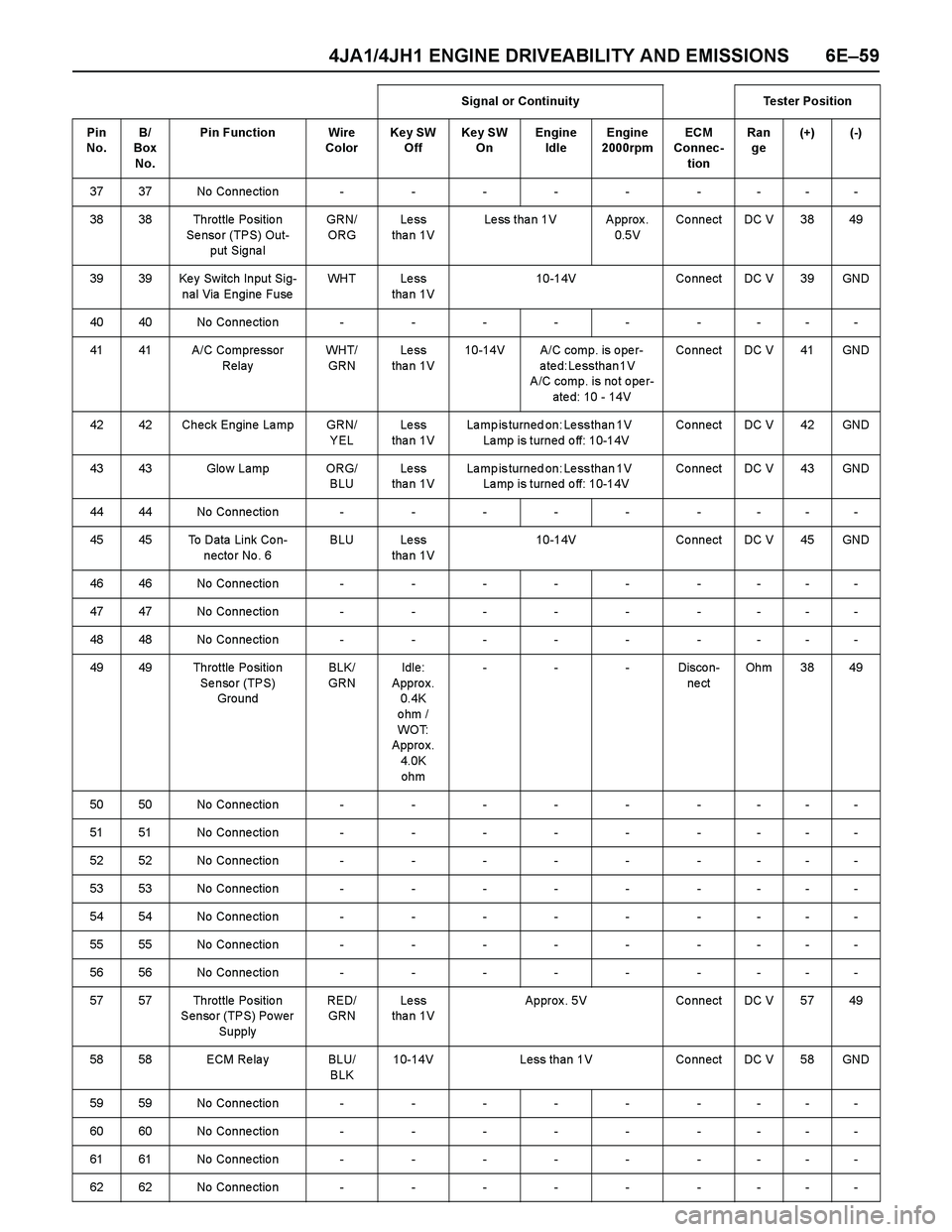
4JA1/4JH1 ENGINE DRIVEABILITY AND EMISSIONS 6E–59
3737No Connection---------
38 38 Throttle Po sitio n
Se nso r (TPS) Out-
put Signa lGRN/
ORGLe ss
tha n 1VLess than 1V Approx.
0.5VCo nnect DC V 38 49
39 39 Ke y Switch Input Sig-
nal Via Engine FuseWH T L e s s
tha n 1V10-14V Co nnect DC V 39 GND
4040No Connection---------
41 41 A/C Compressor
RelayWH T/
GRNLe ss
tha n 1V10-14V A/C comp. is o pe r-
ated: Less than 1V
A/C comp. is no t o pe r-
ate d: 10 - 14VCo nnect DC V 41 GND
42 42 Check Engine La mp GRN/
YELLe ss
tha n 1VLamp is turned on: Less than 1V
Lamp is turned off: 10-14VCo nnect DC V 42 GND
43 43 Glo w Lamp ORG/
BLULe ss
tha n 1VLamp is turned on: Less than 1V
Lamp is turned off: 10-14VCo nnect DC V 43 GND
4444No Connection---------
45 45 To Data Link Co n-
necto r No . 6BLU Less
tha n 1V10-14V Co nnect DC V 45 GND
4646No Connection---------
4747No Connection---------
4848No Connection---------
49 49 Throttle Po sitio n
Se nso r (TPS)
GroundBLK/
GRNIdle:
Appro x.
0.4K
ohm /
WO T:
Appro x.
4.0K
ohm---Discon-
ne ctOh m 3 8 4 9
5050No Connection---------
5151No Connection---------
5252No Connection---------
5353No Connection---------
5454No Connection---------
5555No Connection---------
5656No Connection---------
57 57 Throttle Po sitio n
Senso r (TPS) Po wer
SupplyRED/
GRNLe ss
tha n 1VApprox. 5V Connect DC V 57 49
58 58 ECM Re la y BLU/
BLK10-14V Less than 1V Connect DC V 58 GND
5959No Connection---------
6060No Connection---------
6161No Connection---------
6262No Connection---------Signal or Continuity Tester Position
Pin
No. B/
Box
No.Pin Function Wire
ColorKey SW
OffKey SW
OnEngine
IdleEngine
2000rpmECM
Connec-
tionRan
ge(+) (-)
Page 1432 of 4264

6E–60 4JA1/4JH1 ENGINE DRIVEABILITY AND EMISSIONS
63 63 ECM Po wer Supply - Le ss
tha n 1V10-14V - DC V 63 GND
6464No Connection---------
65 65 Bra ke Switch 2 Sig-
na lWH T/
BLKLe ss
tha n 1VPedal is not stepped on: 10-14V
Pe da l is ste ppe d o n: Le ss tha n 1VCo nnect DC V 65 GND
6666No Connection---------
6767No Connection---------
68 68 Ve hicle Spe ed Sen-
sor (VSS)YEL/
GRN- Appro x. 14.5Hz by wa ve fo rm or
approx. 6.0V at vehicle speed
20km/hCo nnect AC V 68 GND
69 69 Idle Switch GRN/
BLKLe ss
tha n 1VPedal is not stepped on: Less than
1V
Pedal is stepped on: Approx. 5VCo nnect DC V 69 GND
7070No Connection---------
7171No Connection---------
7272No Connection---------
7373No Connection---------
7474No Connection---------
7575No Connection---------
7676No Connection---------
7777No Connection---------
7878No Connection---------
7979No Connection---------
8080No Connection---------
8181No Connection---------
82 82 Boo st Pre ssure Sen-
so r (High Altitude
Spe c. Onl y )WH T/
BLULe ss
tha n 1VApprox. 5V Connect DC V 82 93
83 83 Ma ss Air Flow (MAF)
Se nso r Po wer Sup-
plyWH T/
REDLe ss
tha n 1VApprox. 5V Connect DC V 83 92
84 84 Intake Air Tempera-
ture (IAT) Se nso r
SignalBLK/
BLULe ss
tha n 1V0 deg. C: Approx. 3.6V / 20 deg. C:
Approx. 2.6V / 40 deg. C: Approx.
1.7V / 60 deg. C: 1.1V / 80 deg. C:
0.7VCo nnect DC V 84 92
85 85 Manifo ld Pre ssure
Se nsor (High Alti-
tude Spe c. Only)RED/
BLULe ss
tha n 1V- - - Co nnect DC V 85 93
8686No Connection---------
87 87 Neutra l Switch BLK/
WH TLe ss
tha n 1VIn neutral (A/T: P or N): Less than
1 V
Othe r tha n neutra l (A/T: o ther tha n
P o r N): 10-14VCo nnect DC V 87 GND
88 88 Ma ss Air Flow (MAF)
Sensor SignalGRN/
REDLe ss
tha n 1VAppro x.
1V Approx .
1.8VApprox.
2.5VCo nnect DC V 88 92 Signal or Continuity Tester Position
Pin
No. B/
Box
No.Pin Function Wire
ColorKey SW
OffKey SW
OnEngine
IdleEngine
2000rpmECM
Connec-
tionRan
ge(+) (-)
Page 1438 of 4264
6E–66 4JA1/4JH1 ENGINE DRIVEABILITY AND EMISSIONS
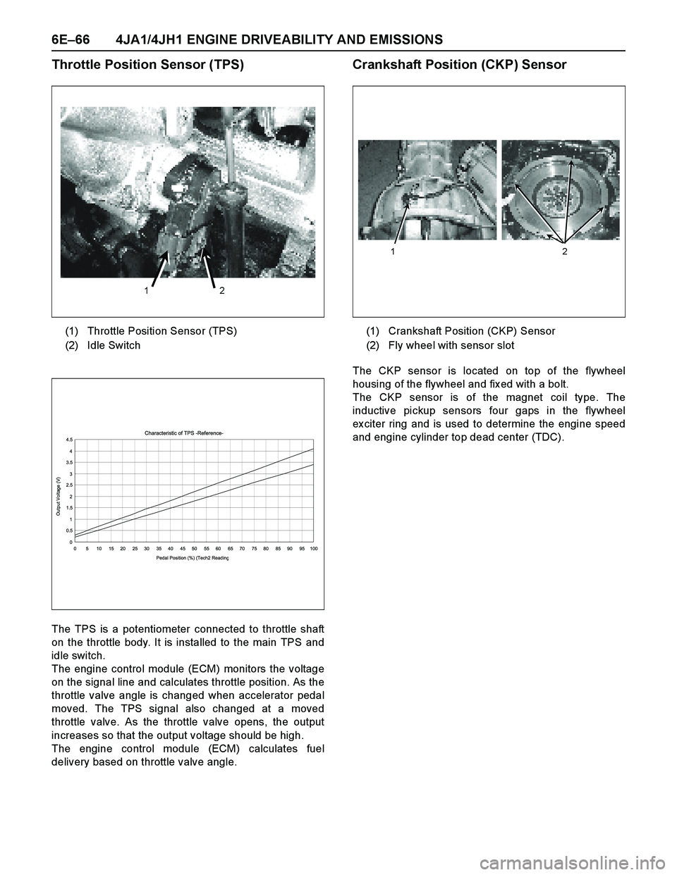
Throttle Position Sensor (TPS)
The TPS is a potentiometer connected to throttle shaft
on the throttle body. It is installed to the main TPS and
idle switch.
The engine control module (ECM) monitors the voltage
on the signal line and calculates throttle position. As the
throttle valve angle is changed when accelerator pedal
moved. The TPS signal also changed at a moved
throttle valve. As the throttle valve opens, the output
increases so that the output voltage should be high.
The engine control module (ECM) calculates fuel
delivery based on throttle valve angle.
Crankshaft Position (CKP) Sensor
The CKP sensor is located on top of the flywheel
housing of the flywheel and fix ed with a bolt.
The CKP sensor is of the magnet coil type. The
inductive pickup sensors four gaps in the flywheel
ex citer ring and is used to determine the engine speed
and engine cylinder top dead center (TDC). (1) Throttle Position Sensor (TPS)
(2) Idle Switch
1 2
Characteristic of TPS -Reference-
0 0.51 1.52 2.53 3.54 4.5
0 5 10 15 20 25 30 35 40 45 50 55 60 65 70 75 80 85 90 95 100
Pedal Position (%) (Tech2 Readin
g
Output Voltage (V)
(1) Crankshaft Position (CKP) Sensor
(2) Fly wheel with sensor slot
1 2
Page 1450 of 4264
6E–78 4JA1/4JH1 ENGINE DRIVEABILITY AND EMISSIONS
3. Check Bulletins and
Troubleshooting Hints
NOTE: As estimated 30 percent of successful vehicle
repairs are diagnosed with this step!
What you should do
You should have enough information gained from
preliminary checks to accurately search for a bulletin
and other related service information. Some service
manual sections provide troubleshooting hints that
match symptoms with specific complaints.
What resources you should use
You should use the following resources for assistance in
checking for bulletins and troubleshooting hints:
Printed bulletins
Access ISUZU Bulletin Web site.
Videotapes
Service manual
4. Perform Service Manual
Diagnostic Checks
What you should do
The “System Checks” in most service manual sections
and in most cells of section 8A (electrical) provide you
with:
A systematic approach to narrowing down the
possible causes of a system fault
Direction to specific diagnostic procedures in the
service manual
Assistance to identify what systems work correctly
What resources you should use
Whenever possible, you should use the following
resources to perform service manual checks:
Service manual
Technical equipment (for viewing DTCs and
analyzing data)
Digital multimeter and circuit testing tools
Other tools as needed
5a and 5b. Perform Service Manual
Diagnostic Procedures
NOTE: An estimated 40 percent of successful vehicle
repairs are diagnosed with these steps!
What you should do
When directed by service manual diagnostic checks,
you must then carefully and accurately perform the
steps of diagnostic procedures to locate the fault relatedto the customer complaint.
What resources you should use
Whenever appropriate, you should use the following
resources to perform service manual diagnostic
procedures:
Service manual
Technical equipment (for analyzing diagnostic data)
Digital multimeter and circuit testing tools
Essential and special tools
5c. Technician Self Diagnoses
When there is no DTC stored and no matching
symptom for the condition identified in the service
manual, you must begin with a thorough understanding
of how the system(s) operates. Efficient use of the
service manual combined with you ex perience and a
good process of elimination will result in accurate
diagnosis of the condition.
What you should do
Step 1: Identify and understand the suspect
circuit(s)
Having completed steps 1 through 4 of the Strategy
Based Diagnostics chart, you should have enough
information to identify the system(s) or sub-system(s)
involved. Using the service manual, you should
determine and investigate the following circuit
characteristics:
Electrical:
–How is the circuit powered (power distribution
charts and/or fuse block details)?
–How is the circuit grounded (ground distribution
charts)?
–How is the circuit controlled or sensed (theory of
operation):
–If it is a switched circuit, is it normally open or
normally closed?
–Is the power switched or is the ground
switched?
–Is it a variable resistance circuit (ECT sensor
or TP sensor, for ex ample)?
–Is it a signal generating device (MAF sensor of
VSS, for example)?
–Does it rely on some mechanical/vacuum
device to operate?
Physical:
–Where are the circuit components (component
locators and wire harness routing diagrams):
–Are there areas where wires could be chafed
or pinched (brackets or frames)?
–Are there areas subjected to ex treme
temperatures?
Page 1451 of 4264
4JA1/4JH1 ENGINE DRIVEABILITY AND EMISSIONS 6E–79
–Are there areas subjected to vibration or
movement (engine, transmission or
suspension)?
–Are there areas ex posed to moisture, road salt
or other corrosives (battery acid, oil or other
fluids)?
–Are there common mounting areas with other
systems/components?
–Have previous repairs been performed to wiring,
connectors, components or mounting areas
(causing pinched wires between panels and
drivetrain or suspension components without
causing and immediate problem)?
–Does the vehicle have aftermarket or dealer-
installed equipment (radios, telephone, etc.)
Step 2: Isolate the problem
At this point, you should have a good idea of what could
cause the present condition, as well as could not cause
the condition. Actions to take include the following:
Divide (and separate, where possible) the system or
circuit into smaller sections
Confine the problem to a smaller area of the vehicle
(start with main harness connections while removing
panels and trim as necessary in order to eliminate
large vehicle sections from further investigation)
For two or more circuits that do not share a common
power or ground, concentrate on areas where
harnesses are routed together or connectors are
shared (refer to the following hints)
Hints
Though the symptoms may vary, basic electrical failures
are generally caused by:
Loose connections:
–Open/high resistance in terminals, splices,
connectors or grounds
Incorrect connector/harness routing (usually in new
vehicles or after a repair has been made):
–Open/high resistance in terminals, splices,
connectors of grounds
Corrosion and wire damage:
–Open/high resistance in terminals, splices,
connectors of grounds
Component failure:
–Opens/short and high resistance in relays,
modules, switches or loads
Aftermarket equipment affecting normal operation of
other systems
You may isolate circuits by:
Unplugging connectors or removing a fuse to
separate one part of the circuit from another part
Operating shared circuits and eliminating those that
function normally from the suspect circuit
If only one component fails to operate, begin testingat the component
If a number of components do no operate, begin tests
at the area of commonality (such as power sources,
ground circuits, switches or major connectors)
What resources you should use
Whenever appropriate, you should use the following
resources to assist in the diagnostic process:
Service manual
Technical equipment (for data analysis)
Ex perience
Technical Assistance
Circuit testing tools
5d. Intermittent Diagnosis
By definition, an intermittent problem is one that does
not occur continuously and will occur when certain
conditions are met. All these conditions, however, may
not be obvious or currently known. Generally,
intermittents are caused by:
Faulty electrical connections and wiring
Malfunctioning components (such as sticking relays,
solenoids, etc.)
EMI/RFI (Electromagnetic/radio frequency
interference)
Aftermarket equipment
Intermittent diagnosis requires careful analysis of
suspected systems to help prevent replacing good
parts. This may involve using creativity and ingenuity to
interpret customer complaints and simulating all
ex ternal and internal system conditions to duplicate the
problem.
What you should do
Step 1: A cquire information
A thorough and comprehensive customer check sheet
is critical to intermittent problem diagnosis. You should
require this, since it will dictate the diagnostic starting
point. The vehicle service history file is another
source for accumulating information about the
complaint.
Step 2: A nalyze the intermittent problem
Analyze the customer check sheet and service history
file to determine conditions relevant to the suspect
system(s).
Using service manual information, you must identify,
trace and locate all electrical circuits related to the
malfunctioning system(s). If there is more than one
system failure, you should identify, trace and locate
areas of commonality shared by the suspect circuits.
Page 1452 of 4264
6E–80 4JA1/4JH1 ENGINE DRIVEABILITY AND EMISSIONS
Step 3: Simulate the symptom and isolate the
problem
Simulate the symptom and isolate the system by
reproducing all possible conditions suggested in Step 1
while monitoring suspected circuits/components/
systems to isolate the problem symptom. Begin with the
most logical circuit/component.
Isolate the circuit by dividing the suspect system into
simpler circuits. Nex t, confine the problem into a smaller
area of the system. Begin at the most logical point (or
point of easiest access) and thoroughly check the
isolated circuit for the fault, using basic circuit tests.
Hints
You can isolate a circuit by:
Unplugging connectors or removing a fuse to
separate one part of the circuit from another
If only component fails to operate, begin testing the
component
If a number of components do not operate, begin test
at areas of commonality (such as power sources,
ground circuits, switches, main connectors or major
components)
Substitute a known good part from the parts
department or the vehicle system
Try the suspect part in a known good vehicle
See Symptom Simulation Tests on the nex t page for
problem simulation procedures. Refer to service manual
sections 6E and 8A for information about intermittent
diagnosis. Follow procedures for basic circuit testing in
service manual section 8A.
What resources you should use
Whenever appropriate, you should use the following
resources to assist in the diagnostic process:
Service manual
Bulletins
Digital multimeter (with a MIN/MAX feature)
Tech II and Tech II upload function
Circuit testing tools (including connector kits/
harnesses and jumper wires)
Ex perience
Intermittent problem solving simulation methods
Customer complaint check sheet
Symptom Simulation Tests
1. Vibration
This method is useful when the customer complaint
analysis indicates that the problem occurs when the
vehicle/system undergoes some form of vibration.
For connectors and wire harness, slightly shake
vertically and horizontally. Inspect the connector joint
and body for damage. Also, tapping lightly along a
suspected circuit may be helpful.For parts and sensors, apply slight vibration to the part
with a light tap of the finger while monitoring the system
for a malfunction.
2. Heat
This method is important when the complaint suggests
that the problem occurs in a heated environment. Apply
moderate heat to the component with a hair drier or
similar tool while monitoring the system for a
malfunction.
CA UTION: Care must be take to avoid overheating
the component.
3. Water and Moisture
This method may be used when the complaint suggests
that the malfunction occurs on a rainy day or under
conditions of high humidity. In this case, apply water in a
light spray on the vehicle to duplicate the problem.
CA UTION: Care must be take to avoid directly
exposing electrical connections to water.
4. Electrical loads
This method involves turning systems ON (such as the
blower, lights or rear window defogger) to create a load
on the vehicle electrical system at the same time you
are monitoring the suspect circuit/component.
5e. Vehicle Operates as Designed
This condition refers to instances where a system
operating as designed is perceived to be unsatisfactory
or undesirable. In general, this is due to:
A lack of understanding by the customer
A conflict between customer ex pectations and
vehicle design intent
A system performance that is unacceptable to the
customer
What you should do
You can verify that a system is operating as designed
by:
Reviewing service manual functional/diagnostic
checks
Ex amining bulletins and other service information for
supplementary information
Compare system operation to an identical vehicle
If the condition is due to a customer misunderstanding
or a conflict between customer ex pectation and system
operation, you should ex plain the system operation to
the customer.
If the complaint is due to a case of unsatisfactory
system performance, you should contact Technical
Assistance for the latest information.
What resources you should use
Whenever possible, you should use the following
resources to facilitate the diagnostic process: