switch ISUZU TF SERIES 2004 Workshop Manual
[x] Cancel search | Manufacturer: ISUZU, Model Year: 2004, Model line: TF SERIES, Model: ISUZU TF SERIES 2004Pages: 4264, PDF Size: 72.63 MB
Page 1454 of 4264
6E–82 4JA1/4JH1 ENGINE DRIVEABILITY AND EMISSIONS
GENERAL SERVICE INFORMATION
Serviceability Issues
Non-OEM Parts
All of the OBD diagnostics have been calibrated to run
with OEM parts. Accordingly, if commercially sold
sensor or switch is installed, it makes a wrong diagnosis
and turns on the check engine lamp.
Aftermarket electronics, such as cellular phones,
stereos, and anti-theft devices, may radiate EMI into the
control system if they are improperly installed. This may
cause a false sensor reading and turn on the check
engine lamp.
Poor Vehicle Maintenance
The sensitivity of OBD diagnostics will cause the check
engine lamp to turn on if the vehicle is not maintained
properly. Restricted oil filters, fuel filters, and crankcase
deposits due to lack of oil changes or improper oil
viscosity can trigger actual vehicle faults that were not
previously monitored prior to OBD. Poor vehicle
maintenance can not be classified as a “non-vehicle
fault”, but with the sensitivity of OBD diagnostics,
vehicle maintenance schedules must be more closely
followed.
Related System Faults
Many of the OBD system diagnostics will not run if the
ECM detects a fault on a related system or component.
Visual/Physical Engine Compartment
Inspection
Perform a careful visual and physical engine
compartment inspection when performing any
diagnostic procedure or diagnosing the cause of an
emission test failure. This can often lead to repairing a
problem without further steps. Use the following
guidelines when performing a visual/physical
inspection:
Inspect all vacuum hoses for punches, cuts,
disconnects, and correct routing.
Inspect hoses that are difficult to see behind other
components.
Inspect all wires in the engine compartment for
proper connections, burned or chafed spots, pinched
wires, contact with sharp edges or contact with hot
exhaust manifolds or pipes.
Basic Knowledge of Tools Required
NOTE: Lack of basic knowledge of this powertrain
when performing diagnostic procedures could result in
an incorrect diagnosis or damage to powertrain
components. Do not attempt to diagnose a powertrain
problem without this basic knowledge.
A basic understanding of hand tools is necessary to
effectively use this section of the Service Manual.
ON-BOARD DIAGNOSTIC (OBD)
On-Board Diagnostic (Self Diagnosis
System) Tests
A diagnostic test is a series of steps, the result of which
is a pass or fail reported to the diagnostic ex ecutive.
When a diagnostic test reports a pass result, the
diagnostic ex ecutive records the following data:
The diagnostic test has been completed since the
last ignition cycle.
The diagnostic test has passed during the current
ignition cycle.
The fault identified by the diagnostic test is not
currently active.
When a diagnostic test reports a fail result, the
diagnostic ex ecutive records the following data:
The diagnostic test has been completed since the
last ignition cycle.
The fault identified by the diagnostic test is currently
active.
The fault has been active during this ignition cycle.
The operating conditions at the time of the failure.
The Diagnostic Executive
The Diagnostic Executive is a unique segment of
software which is designed to coordinate and prioritize
the diagnostic procedures as well as define the protocol
for recording and displaying their results. The main
responsibilities of the Diagnostic Ex ecutive are listed as
follow s:
Commanding the check engine lamp on and off
DTC logging and clearing
Current status information on each diagnostic
Diagnostic Information
The diagnostic charts and functional checks are
designed to locate a faulty circuit or component through
a process of logical decisions. The charts are prepared
with the requirement that the vehicle functioned
correctly at the time of assembly and that there are not
multiple faults present.
There is a continuous self-diagnosis on certain control
functions. This diagnostic capability is complemented
by the diagnostic procedures contained in this manual.
The language of communicating the source of the
malfunction is a system of diagnostic trouble codes.
When a malfunction is detected by the control module, a
diagnostic trouble code is set and the check engine
lamp is illuminated.
Check Engine Lamp
The check engine lamp looks the same as the check
engine lamp you are already familiar with, the “Check
Engine” lamp.
Basically, the check engine lamp is turned on when the
Page 1455 of 4264
4JA1/4JH1 ENGINE DRIVEABILITY AND EMISSIONS 6E–83
ECM detects a DTC that will impact the vehicle
emissions.
When the check engine lamp remains “ON” while the
engine is running, or when a malfunction is
suspected due to a driveability or emissions problem,
a Powertrain On-Board Diagnostic (OBD) System
Check must be performed. The procedures for these
checks are given in On-Board Diagnostic (OBD)
System Check. These checks will ex pose faults
which may not be detected if other diagnostics are
performed first.
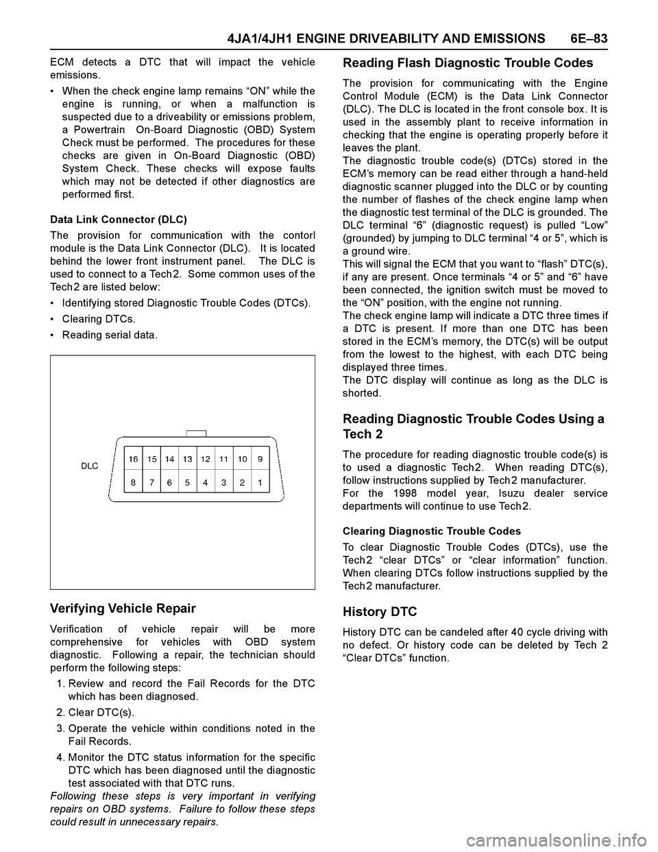
Data Link Connector (DLC)
The provision for communication with the contorl
module is the Data Link Connector (DLC). It is located
behind the lower front instrument panel. The DLC is
used to connect to a Tech 2. Some common uses of the
Tech 2 are listed below:
Identifying stored Diagnostic Trouble Codes (DTCs).
Clearing DTCs.
Reading serial data.
Verifying Vehicle Repair
Verification of vehicle repair will be more
comprehensive for vehicles with OBD system
diagnostic. Following a repair, the technician should
perform the following steps:
1. Review and record the Fail Records for the DTC
which has been diagnosed.
2. Clear DTC(s).
3. Operate the vehicle within conditions noted in the
Fail Records.
4. Monitor the DTC status information for the specific
DTC which has been diagnosed until the diagnostic
test associated with that DTC runs.
Following these steps is very important in verifying
repairs on OBD systems. Failure to follow these steps
could result in unnecessary repairs.
Reading Flash Diagnostic Trouble Codes
The provision for communicating with the Engine
Control Module (ECM) is the Data Link Connector
(DLC). The DLC is located in the front console box . It is
used in the assembly plant to receive information in
checking that the engine is operating properly before it
leaves the plant.
The diagnostic trouble code(s) (DTCs) stored in the
ECM’s memory can be read either through a hand-held
diagnostic scanner plugged into the DLC or by counting
the number of flashes of the check engine lamp when
the diagnostic test terminal of the DLC is grounded. The
DLC terminal “6” (diagnostic request) is pulled “Low”
(grounded) by jumping to DLC terminal “4 or 5”, which is
a ground wire.
This will signal the ECM that you want to “flash” DTC(s),
if any are present. Once terminals “4 or 5” and “6” have
been connected, the ignition switch must be moved to
the “ON” position, with the engine not running.
The check engine lamp will indicate a DTC three times if
a DTC is present. If more than one DTC has been
stored in the ECM’s memory, the DTC(s) will be output
from the lowest to the highest, with each DTC being
displayed three times.
The DTC display will continue as long as the DLC is
shorted.
Reading Diagnostic Trouble Codes Using a
Tech 2
The procedure for reading diagnostic trouble code(s) is
to used a diagnostic Tech 2. When reading DTC(s),
follow instructions supplied by Tech 2 manufacturer.
For the 1998 model year, Isuzu dealer service
departments will continue to use Tech 2.
Clearing Diagnostic Trouble Codes
To clear Diagnostic Trouble Codes (DTCs), use the
Te c h 2 “clear DTCs” or “clear information” function.
When clearing DTCs follow instructions supplied by the
Tech 2 manufacturer.
History DTC
History DTC can be candeled after 40 cycle driving with
no defect. Or history code can be deleted by Tech 2
“Clear DTCs” function.
Page 1457 of 4264
4JA1/4JH1 ENGINE DRIVEABILITY AND EMISSIONS 6E–85
DIAGNOSIS WITH Tech 2
If no codes are set:
Refer to F1: Data Display and identify the electrical
faults that are not indicated by trouble code.
Refer to “SYMPTOM DIAGNOSIS”.
If codes are set:
1. Record all trouble codes displayed by Tech 2 and
check id the codes are intermittent.
2. Clear the codes.
3. Drive the vehicle for a test to reproduce the faulty
status.
4. Check trouble codes again using the Tech 2.
5. If no codes is displayed by test driving, the fault is
intermittent. In this case, refer to “DIAGNOSIS
AIDS”.
6. If a code is present, refer to DTC Chart for
diagnosis.
7. Check trouble codes again using the Tech 2.
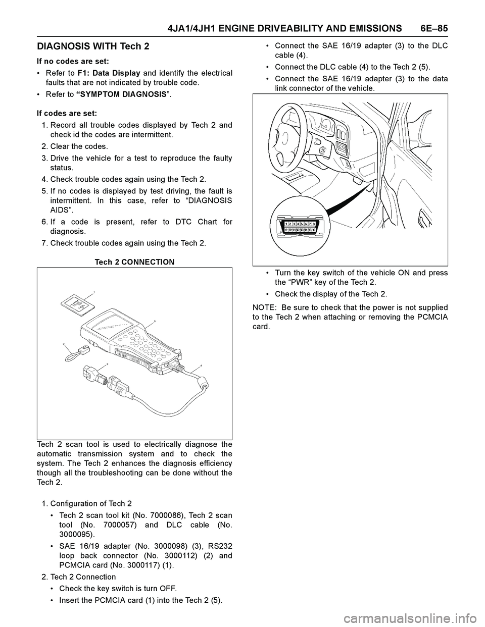
Tech 2 CONNECTION
Tech 2 scan tool is used to electrically diagnose the
automatic transmission system and to check the
system. The Tech 2 enhances the diagnosis efficiency
though all the troubleshooting can be done without the
Te c h 2 .
1. Configuration of Tech 2
Tech 2 scan tool kit (No. 7000086), Tech 2 scan
tool (No. 7000057) and DLC cable (No.
3000095).
SAE 16/19 adapter (No. 3000098) (3), RS232
loop back connector (No. 3000112) (2) and
PCMCIA card (No. 3000117) (1).
2. Tech 2 Connection
Check the key switch is turn OFF.
Insert the PCMCIA card (1) into the Tech 2 (5).Connect the SAE 16/19 adapter (3) to the DLC
cable (4).
Connect the DLC cable (4) to the Tech 2 (5).
Connect the SAE 16/19 adapter (3) to the data
link connector of the vehicle.
Turn the key switch of the vehicle ON and press
the “PWR” key of the Tech 2.
Check the display of the Tech 2.
NOTE: Be sure to check that the power is not supplied
to the Tech 2 when attaching or removing the PCMCIA
card.
Page 1460 of 4264
6E–88 4JA1/4JH1 ENGINE DRIVEABILITY AND EMISSIONS
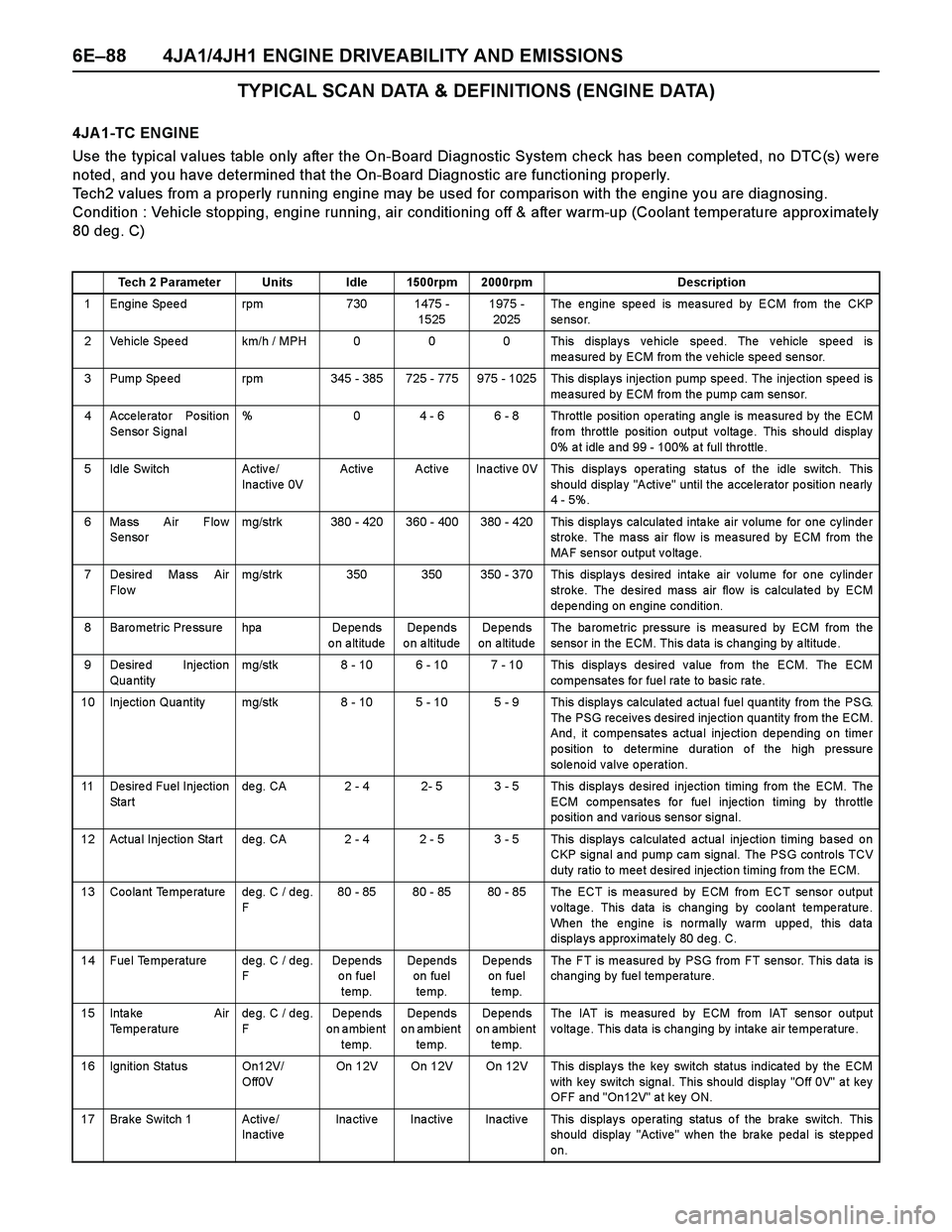
TYPICAL SCAN DATA & DEFINITIONS (ENGINE DATA)
4JA 1-TC ENGINE
Use the typical values table only after the On-Board Diagnostic System check has been completed, no DTC(s) were
noted, and you have determined that the On-Board Diagnostic are functioning properly.
Tech2 values from a properly running engine may be used for comparison with the engine you are diagnosing.
Condition : Vehicle stopping, engine running, air conditioning off & after warm-up (Coolant temperature approx imately
80 deg. C)
Tech 2 Parameter Units Idle 1500rpm 2000rpm Description
1 Engine Speed rpm 730 1475 -
15251975 -
2025The engine speed is measured by ECM from the CKP
se nso r.
2 Vehicle Speed km/h / MPH 0 0 0 This displays vehicle speed. The vehicle speed is
measured by ECM from the vehicle speed sensor.
3 Pump Spe ed rpm 345 - 385 725 - 775 975 - 1025 This displa ys injectio n pump spe ed. The inje ction spe ed is
measured by ECM from the pump cam sensor.
4 Accelerator Position
Sensor Signal% 0 4 - 6 6 - 8 Throttle position operating angle is measured by the ECM
fro m throttle po sition o utput v olta ge . This sho uld display
0% a t idle a nd 99 - 100% a t full thro ttle .
5 Idle Switch Activ e /
Inactive 0VActive Active Inactive 0V This displays operating status of the idle switch. This
should display "Active" until the accelerator position nearly
4 - 5%.
6 Mass Air Flow
Sensormg/strk 380 - 420 360 - 400 380 - 420 This displays calculated intake air volume for one cylinder
stroke. The mass air flow is measured by ECM from the
MAF sensor output voltage.
7 Desire d Ma ss Air
Flo wmg/strk 350 350 350 - 370 This displays desired intake air volume for one cylinder
stroke. The desired mass air flow is calculated by ECM
de pe nding on engine conditio n.
8 Baro metric Pre ssure hpa De pe nds
on altitudeDe pe nds
o n a ltitudeDe pe nds
on altitudeThe ba rome tric pre ssure is mea sure d by ECM from the
sensor in the ECM. This data is changing by altitude.
9 Desired Injection
Qua ntitymg/stk 8 - 10 6 - 10 7 - 10 This displays desired value from the ECM. The ECM
co mpe nsates fo r fue l ra te to ba sic ra te.
10 Injection Qua ntity mg/stk 8 - 10 5 - 10 5 - 9 This displa y s ca lculated a ctua l fue l qua ntity from the PSG.
The PSG receives desired injection quantity from the ECM.
And, it compensates actual injection depending on timer
po sitio n to de termine duration o f the high pre ssure
solenoid valve operation.
11 Desire d Fuel Injection
St a r tde g. CA 2 - 4 2- 5 3 - 5 This display s de sired injection timing from the ECM. The
ECM compensates for fuel injection timing by throttle
position and various sensor signal.
12 Actua l Injectio n Sta rt de g. CA 2 - 4 2 - 5 3 - 5 This display s ca lculate d a ctua l inje ctio n timing ba se d o n
CKP signa l a nd pump ca m signal. The PSG controls TCV
duty ra tio to mee t desired inje ctio n timing from the ECM.
13 Coolant Temperature deg. C / deg.
F80 - 85 80 - 85 80 - 85 The ECT is measured by ECM from ECT sensor output
voltage. This data is changing by coolant temperature.
When the engine is normally warm upped, this data
displays approximately 80 deg. C.
14 Fuel Temperature deg. C / deg.
FDe pe nds
on fuel
temp.De pe nds
on fuel
te mp.De pe nds
on fuel
te mp.The FT is measured by PSG from FT sensor. This data is
changing by fuel temperature.
15 Inta ke Air
Temperaturedeg. C / deg.
FDe pe nds
on ambient
temp.De pe nds
on ambient
te mp.De pe nds
on ambient
te mp.The IAT is measured by ECM from IAT sensor output
voltage. This data is changing by intake air temperature.
16 Ignition Status On12V/
Off0VOn 12V On 12V On 12V This displays the key switch status indicated by the ECM
with key switch signal. This should display "Off 0V" at key
OFF and "On12V" at key ON.
17 Brake Switch 1 Active/
InactiveInactive Inactive Inactive This displays operating status of the brake switch. This
should display "Active" when the brake pedal is stepped
on.
Page 1461 of 4264

4JA1/4JH1 ENGINE DRIVEABILITY AND EMISSIONS 6E–89
18 Brake Switch 2 Active/
InactiveInactive Inactive Inactive This displays operating status of the brake switch. This
should display "Active" when the brake pedal is stepped
on.
19 Clutch Sw itch Activ e /
InactiveInactive Inactive Inactive This displays operating status of the clutch switch. This
should display "Active" when the clutch pedal is stepped
on.
20 Neutra l Switch On/Off On On On This displa ys o pe rating status of the neutra l switch. This
should display "On" when the gear position is neutral.
21 A/C Informa tion
SwitchActive 12V/
Inactive 0VInactive 0V Inactive 0V Inactive 0V This displays the air conditioner request signal. This
should display "Active 12V" when the air conditioner switch
is switched on.
22 Dia gnostic Re quest Activ e 0V/
Inactive 12VIna ctiv e
12VInactive
12VIna ctiv e
12VThis display s the dia gnostic reque st signal. This sho uld
display "Inactive 12V" when the Tech 2 is connected.
23 System Voltage V 10 - 14 10 - 14 10 - 14 This displays the system voltage measured by the ECM at
ignition feed.
24 Ma in Re la y Activ e /
InactiveActive Active Active This displays operating status for the ECM main relay. This
should display "Active" when the key switch is turned on
and while engine is running.
25 Glow Time Relay Activ e 0V/
Inactive12VIna ctiv e
12VInactive
12VIna ctiv e
12VThis displays operating status for the glow relay. This
should display "Inactive 12V" when the engine is warm
uppe d.
26 Check Engine Light On/Off Off Off Off This displays operating status for the Check Engine Lamp.
This should display "On" when the Check Engine Lamp is
turned on.
27 Glow Time Telltale On/Off Off Off Off This displays operating status for the glow indicator lamp.
This sho uld display "On" whe n the glo w la mp is turne d o n.
28 Desired Engine Idle
Speedrpm 730 730 730 The desired engine idle speed that the ECM commanding.
The ECM compensates for various engine loads based on
engine coolant temperature.
29 A/C Re que st Activ e 0V/
Inactive 12VIna ctiv e
12VInactive
12VIna ctiv e
12VThis displays operating status of the A/C compressor. This
should display "Active 0V" when the compressor relay is
operated.
30 Immo bilize r Activ e /
InactiveInactive Inactive Inactive This should display "Inactive" when the immobilizer is
correctly operated.
31 Immo bilize r Signal Rece iv ed/
Not
Rece iv edNo t
Receive dNo t
Re ceive dNot
Re ce iv e dThis sho uld displa y "No t Receive d" whe n the immo bilize r is
not activated.
32 Immo bilize r Function
ProgrammedYes/ No Yes Yes Yes This should display "Yes" when the immobilizer is correctly
programmed.
33 EGR Pulse Ratio
(Ex ha ust Ga s
Recirculatio n)% 70 70 70 This displays the duty signal from the ECM to control the
EGR flow amount. Tech 2 Parameter Units Idle 1500rpm 2000rpm Description
Page 1462 of 4264
6E–90 4JA1/4JH1 ENGINE DRIVEABILITY AND EMISSIONS
TYPICAL SCAN DATA & DEFINITIONS (ENGINE DATA)
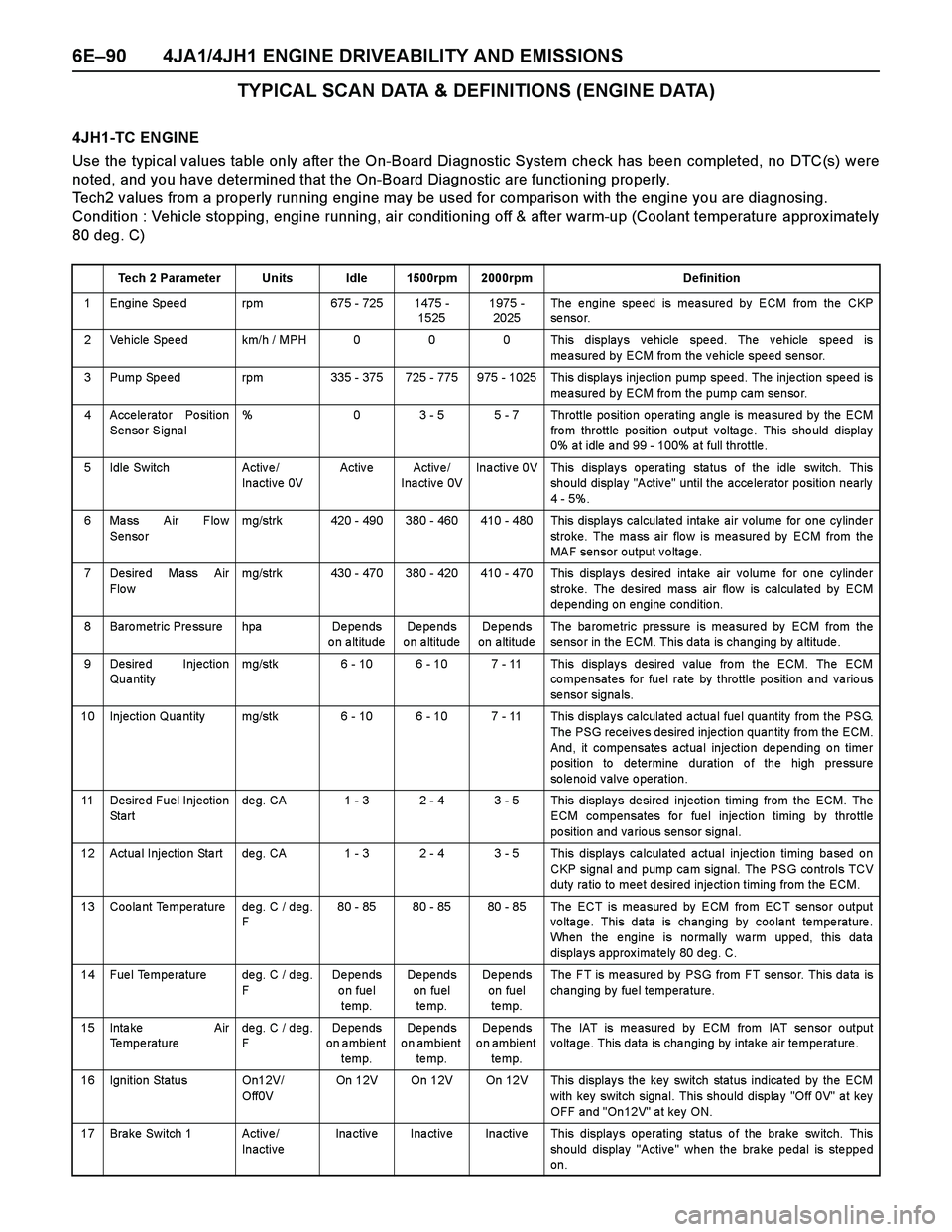
4JH1-TC ENGINE
Use the typical values table only after the On-Board Diagnostic System check has been completed, no DTC(s) were
noted, and you have determined that the On-Board Diagnostic are functioning properly.
Tech2 values from a properly running engine may be used for comparison with the engine you are diagnosing.
Condition : Vehicle stopping, engine running, air conditioning off & after warm-up (Coolant temperature approx imately
80 deg. C)
Tech 2 Parameter Units Idle 1500rpm 2000rpm Definition
1 Engine Speed rpm 675 - 725 1475 -
15251975 -
2025The engine speed is measured by ECM from the CKP
se nso r.
2 Vehicle Speed km/h / MPH 0 0 0 This displays vehicle speed. The vehicle speed is
measured by ECM from the vehicle speed sensor.
3 Pump Spe ed rpm 335 - 375 725 - 775 975 - 1025 This displa ys injectio n pump spe ed. The inje ction spe ed is
measured by ECM from the pump cam sensor.
4 Accelerator Position
Sensor Signal% 0 3 - 5 5 - 7 Throttle position operating angle is measured by the ECM
fro m throttle po sition o utput v olta ge . This sho uld display
0% a t idle a nd 99 - 100% a t full throttle .
5 Idle Switch Activ e /
Inactive 0VActive Active/
Inactive 0VInactive 0V This displays operating status of the idle switch. This
should display "Active" until the accelerator position nearly
4 - 5%.
6 Mass Air Flow
Sensormg/strk 420 - 490 380 - 460 410 - 480 This displays calculated intake air volume for one cylinder
stroke. The mass air flow is measured by ECM from the
MAF sensor output voltage.
7 Desire d Ma ss Air
Flo wmg/strk 430 - 470 380 - 420 410 - 470 This displays desired intake air volume for one cylinder
stroke. The desired mass air flow is calculated by ECM
de pe nding on engine conditio n.
8 Baro metric Pre ssure hpa De pe nds
on altitudeDe pe nds
o n a ltitudeDe pe nds
on altitudeThe ba rome tric pre ssure is mea sure d by ECM from the
sensor in the ECM. This data is changing by altitude.
9 Desired Injection
Qua ntitymg/stk 6 - 10 6 - 10 7 - 11 This displays desired value from the ECM. The ECM
co mpe nsates for fuel rate by thro ttle po sition a nd va rio us
se nso r signa ls.
10 Injection Qua ntity mg/stk 6 - 10 6 - 10 7 - 11 This displa y s ca lculated a ctua l fue l qua ntity from the PSG.
The PSG receives desired injection quantity from the ECM.
And, it compensates actual injection depending on timer
po sitio n to de termine duration o f the high pre ssure
solenoid valve operation.
11 Desire d Fuel Injection
St a r tde g. CA 1 - 3 2 - 4 3 - 5 This display s de sired injection timing from the ECM. The
ECM compensates for fuel injection timing by throttle
position and various sensor signal.
12 Actua l Injectio n Sta rt de g. CA 1 - 3 2 - 4 3 - 5 This display s ca lculate d a ctua l inje ctio n timing ba se d o n
CKP signa l a nd pump ca m signal. The PSG controls TCV
duty ra tio to mee t desired inje ctio n timing from the ECM.
13 Coolant Temperature deg. C / deg.
F80 - 85 80 - 85 80 - 85 The ECT is measured by ECM from ECT sensor output
voltage. This data is changing by coolant temperature.
When the engine is normally warm upped, this data
displays approximately 80 deg. C.
14 Fuel Temperature deg. C / deg.
FDe pe nds
on fuel
temp.De pe nds
on fuel
te mp.De pe nds
on fuel
te mp.The FT is measured by PSG from FT sensor. This data is
changing by fuel temperature.
15 Inta ke Air
Temperaturedeg. C / deg.
FDe pe nds
on ambient
temp.De pe nds
on ambient
te mp.De pe nds
on ambient
te mp.The IAT is measured by ECM from IAT sensor output
voltage. This data is changing by intake air temperature.
16 Ignition Status On12V/
Off0VOn 12V On 12V On 12V This displays the key switch status indicated by the ECM
with key switch signal. This should display "Off 0V" at key
OFF and "On12V" at key ON.
17 Brake Switch 1 Active/
InactiveInactive Inactive Inactive This displays operating status of the brake switch. This
should display "Active" when the brake pedal is stepped
on.
Page 1463 of 4264

4JA1/4JH1 ENGINE DRIVEABILITY AND EMISSIONS 6E–91
18 Brake Switch 2 Active/
InactiveInactive Inactive Inactive This displays operating status of the brake switch. This
should display "Active" when the brake pedal is stepped
on.
19 Clutch Switch (M/T
On ly )Active/
InactiveInactive Inactive Inactive This displays operating status of the clutch switch. This
should display "Active" when the clutch pedal is stepped
on.
20 Neutra l Switch On/Off On On On This displa ys o pe rating status of the neutra l switch. This
should display "On" when the gear position is neutral (M/T)
or P, N positio n (A/T).
21 A/C Informa tion
SwitchActive 12V/
Inactive 0VInactive 0V Inactive 0V Inactive 0V This displays the air conditioner request signal. This
should display "Active 12V" when the air conditioner switch
is switched on.
22 Dia gnostic Re quest Activ e 0V/
Inactive 12VIna ctiv e
12VInactive
12VIna ctiv e
12VThis displays the diagnostic request signal. This should
display "Inactive 12V" when the Tech 2 is connected.
23 System Voltage V 10 - 15 10 - 15 10 - 15 This displays the system voltage measured by the ECM at
ignition feed.
24 Ma in Re la y Activ e /
InactiveActive Active Active This displays operating status for the ECM main relay. This
should display "Active" when the key switch is turned on
and while engine is running.
25 Glow Time Relay Activ e 0V/
Inactive12VIna ctiv e
12VInactive
12VIna ctiv e
12VThis displays operating status for the glow relay. This
should display "Inactive 12V" when the engine is warm
uppe d.
26 Check Engine Light On/Off Off Off Off This displays operating status for the Check Engine Lamp.
This should display "On" when the Check Engine Lamp is
turned on.
27 Glow Time Telltale On/Off Off Off Off This displays operating status for the glow indicator lamp.
This sho uld display "On" whe n the glo w la mp is turne d o n.
28 Desired Engine Idle
Speedrpm 700 700 700 The desired engine idle speed that the ECM commanding.
The ECM compensates for various engine loads based on
engine coolant temperature.
29 A/C Re que st Activ e 0V/
Inactive 12VIna ctiv e
12VInactive
12VIna ctiv e
12VThis displays operating status of the A/C compressor. This
should display "Active 0V" when the compressor relay is
operated.
30 Immo bilize r Activ e /
InactiveInactive Inactive Inactive This should display "Inactive" when the immobilizer is
correctly operated.
31 Immo bilize r Signal Rece iv ed/
Not
Rece iv edNo t
Receive dNot
Re ceive dNot
Re ce iv e dThis sho uld displa y "No t Receive d" whe n the immo bilize r is
not activated.
32 Immo bilize r Function
ProgrammedYes/ No Yes Yes Yes This should display "Yes" when the immobilizer is correctly
programmed.
33 EGR Pulse Ratio
(Ex ha ust Ga s
Recirculatio n)% 85 - 90 85 - 90 85 - 90 This displays the duty signal from the ECM to control the
EGR flow amount. Tech 2 Parameter Units Idle 1500rpm 2000rpm Definition
Page 1472 of 4264
6E–100 4JA1/4JH1 ENGINE DRIVEABILITY AND EMISSIONS
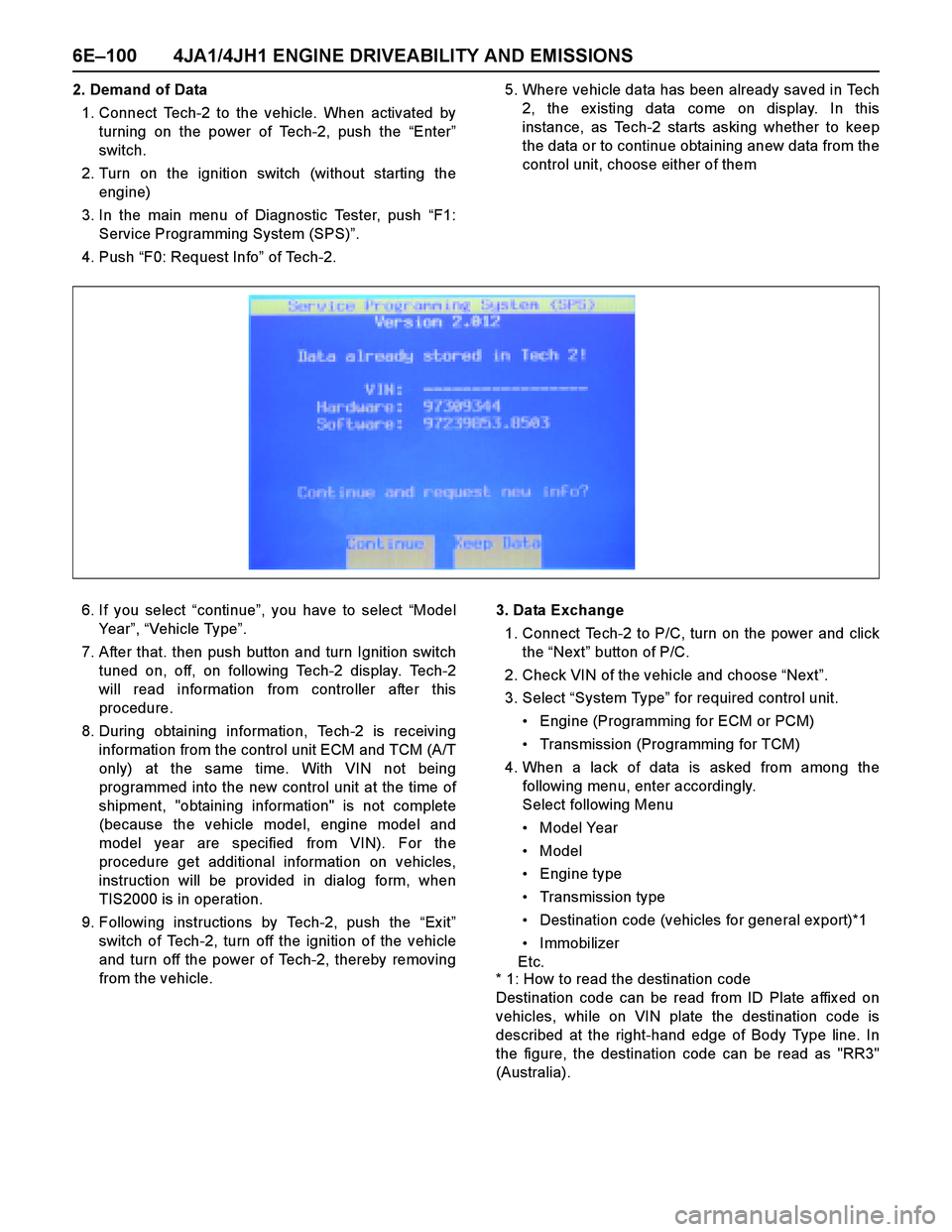
2. Demand of Data
1. Connect Tech-2 to the vehicle. When activated by
turning on the power of Tech-2, push the “Enter”
switch.
2. Turn on the ignition switch (without starting the
engine)
3. In the main menu of Diagnostic Tester, push “F1:
Service Programming System (SPS)”.
4. Push “F0: Request Info” of Tech-2.5. Where vehicle data has been already saved in Tech
2, the ex isting data come on display. In this
instance, as Tech-2 starts asking whether to keep
the data or to continue obtaining anew data from the
control unit, choose either of them
6. If you select “continue”, you have to select “Model
Year”, “Vehicle Type”.
7. After that. then push button and turn Ignition switch
tuned on, off, on following Tech-2 display. Tech-2
will read information from controller after this
procedure.
8. During obtaining information, Tech-2 is receiving
information from the control unit ECM and TCM (A/T
only) at the same time. With VIN not being
programmed into the new control unit at the time of
shipment, "obtaining information" is not complete
(because the vehicle model, engine model and
model year are specified from VIN). For the
procedure get additional information on vehicles,
instruction will be provided in dialog form, when
TIS2000 is in operation.
9. Following instructions by Tech-2, push the “Ex it”
switch of Tech-2, turn off the ignition of the vehicle
and turn off the power of Tech-2, thereby removing
from the vehicle.3. Data Exchange
1. Connect Tech-2 to P/C, turn on the power and click
the “Next” button of P/C.
2. Check VIN of the vehicle and choose “Next”.
3. Select “System Type” for required control unit.
Engine (Programming for ECM or PCM)
Transmission (Programming for TCM)
4. When a lack of data is asked from among the
following menu, enter accordingly.
Select following Menu
Model Year
Model
Engine type
Transmission type
Destination code (vehicles for general export)*1
Immobilizer
Etc.
* 1: How to read the destination code
Destination code can be read from ID Plate affix ed on
vehicles, while on VIN plate the destination code is
described at the right-hand edge of Body Type line. In
the figure, the destination code can be read as "RR3"
(Australia).
Page 1473 of 4264

4JA1/4JH1 ENGINE DRIVEABILITY AND EMISSIONS 6E–101
5. After choosing the data, click the “Nex t” button.
6. When all the necessary information is entered, the
“details” of software within the database that match
the entered data will appear for confirmation. Click
the “Program” switch and then download the new
software onto Tech-2.
7.“Data Transfer” comes on display. The progress of
downloading will be displayed on the screen in the
form of bar graph.
8. Upon finishing the data transfer, turn off the power
of Tech-2, removing from P/C.4. Programming of ECM
1. Check to see if batteries are fully charged, while
ABS connectors shall be removed from the vehicle.
2. Connect Tech-2 to Vehicle Diagnostic Connectors.
3. Turn on the power of Tech-2 and the title screen
comes on display.
4. Turn on the ignition (without allowing the engine to
start)
5. On the title screen of Tech-2, push the “Enter”
button.
6. Choose “F1: Service Programming System” on the
main screen and then choose “Fl: Program ECU”.
7. While data is being transferred, “Programming in
Progress” will be displayed on the Tech-2 screen.
8. Upon finishing the data transfer, Tech-2 will display
“Reprogramming Was Successful”. Push the “Exit”
button to bring program to completion
9. Following “Procedure 2: Demand of Data”, try over
again “Information Obtaining” and check to confirm
if the data has been correctly re-loaded.
10. Upon finishing confirmation, turn off the ignition of
the vehicle and then turn off the power of Tech-2,
removing from the vehicle.
Page 1488 of 4264

6E–116 4JA1/4JH1 ENGINE DRIVEABILITY AND EMISSIONS
52 P0215 A ON Fuel Cutoff Solenoid Valve
Malfunction1. Ignition key switch off.
2. Engine speed is below
1 5 0 0 r p m .
3. Vehicle speed is below
1 . 5 k m / h .
4. PSG (pump control unit)
recognizes MAB (fuel
cutoff solenoid valve)
signal from the ECM, but
the MAB could not
operate. 1. MAB (fuel cutoff solenoid
v a l v e ) i s o p e r a t e d .
2. Desired injection quantity
becomes 0mg/strk.No recovery until condition
match in the next ignition key
cycle.1. PSG (pump control unit)
m a l f u n c t i o n .
2. MAB (fuel cutoff solenoid
valve) malfunction.
——
B ON Fuel Cutoff Solenoid Valve
Circuit High InputECM does not command
MAB (fuel cutoff solenoid
valve) signal to the PSG
(pump control unit), but PSG
detected MAB signal line
circuit is high level.Engine does not start. No recovery. 1. MAB (fuel cutoff solenoid
valve) signal circuit short
t o v o l t a g e c i r c u i t .
2. PSG (pump control unit)
malfunction.105 —
C ON Fuel Cutoff Solenoid Valve
Always Active1. Ignition key switch off.
2. Engine speed is below
1 5 0 0 r p m .
3. Vehicle speed is below
1 . 5 k m / h .
4. PSG (pump control unit)
does not recognize MAB
(fuel cutoff solenoid
valve) signal from the
ECM. 1. MAB (fuel cutoff solenoid
v a l v e ) i s o p e r a t e d .
2. Desired injection quantity
becomes 0mg/strk.No recovery until condition
match in the next ignition key
cycle.1. MAB (fuel cutoff solenoid
valve) signal circuit open
or short to ground circuit.
2. PSG (pump control unit)
malfunction.
105 —
D ON Fuel Cutoff Solenoid Valve
Malfunction1. Ignition key switch off.
2. CAN controller does not
operate Bus-off.N o f a i l - s a f e f u n c t i o n . 1 . E C M m a l f u n c t i o n .
2. PSG (pump control unit)
malfunction.——
54 P0216 A ON Injection Timing Control
Circuit Malfunction1. Engine speed is more
t h a n 7 0 0 r p m .
2. Fuel injection quantity is
more than 4mg/stk.
3. Deviation of actual
injection timing and
desired injection timing is
more than +3 deg. CA or
-6 deg. CA for 8 seconds.Fuel injection quantity is
reduced.Deviation of actual injection
timing and desired injection
timing is more than +3 deg.
CA or -6 deg. CA for 8
seconds.1. Timing control valve
m a l f u n c t i o n .
2 . T i m e r p i s t o n s t i c k i n g .
3. Pump camshaft speed
sensor malfunction.——
B ON Injection Timing Control
Circuit Malfunction 1. Engine speed is more
t h a n 2 0 1 4 r p m .
2. Fluctuation of actual
injection timing is more
than +-5.2 deg. CA.1. Engine speed is more
than 2014rpm.
2. Fluctuation of actual
injection timing is more
than +-5.2 deg. CA.1. Insufficient air bleeding of
f u e l l i n e .
2. Fuel filter clogging.
3. Timing control valve
m a l f u n c t i o n .
4. Pump camshaft speed
sensor malfunction. —— Flash
CodeCodeSymptom
CodeMILDTC Name DTC Setting Condition Fail-Safe (Back Up) Recovery Condition Related Failure PartsRelated
ECM Pin
No.Related
Multiple
DTC4JA1-TC
(MT)4JH1-TC
(MT)4JH1-TC
(AT)