engine coolant ISUZU TF SERIES 2004 Owner's Guide
[x] Cancel search | Manufacturer: ISUZU, Model Year: 2004, Model line: TF SERIES, Model: ISUZU TF SERIES 2004Pages: 4264, PDF Size: 72.63 MB
Page 1380 of 4264
6E–8 4JA1/4JH1 ENGINE DRIVEABILITY AND EMISSIONS
(SYMPTOM CODE B) (FLASH CODE 76) ECM
MAIN RELAY SWITCHED OFF TOO LATE 6E-337
Circuit Description ..................................... 6E-337
Diagnostic Aids .......................................... 6E-337
Diagnostic Trouble Code (DTC) P1625
(Symptom Code A) (Flash Code 76) ECM
Main Relay Switched Off Too Early ......... 6E-338
Diagnostic Trouble Code (DTC) P1625
(Symptom Code B) (Flash Code 76) ECM
Main Relay Switched Off Too Late .......... 6E-339
DIAGNOSTIC TROUBLE CODE (DTC) P1630
(SYMPTOM CODE A) (FLASH CODE 51)
FUEL INJECTION QUANTITY CIRCUIT
MALFUNCTION ....................................... 6E-340
DIAGNOSTIC TROUBLE CODE (DTC) P1630
(SYMPTOM CODE B) (FLASH CODE 51)
FUEL INJECTION QUANTITY CIRCUIT
MALFUNCTION ....................................... 6E-340
Circuit Description ..................................... 6E-340
Diagnostic Aids .......................................... 6E-341
Diagnostic Trouble Code (DTC) P1630
(Symptom Code A) (Flash Code 51) Fuel
Injection Quantity Circuit Malfunction ...... 6E-341
Diagnostic Trouble Code (DTC) P1630
(Symptom Code B) (Flash Code 51) Fuel
Injection Quantity Circuit Malfunction ...... 6E-341
DIAGNOSTIC TROUBLE CODE (DTC) P1650
(SYMPTOM CODE A)
(FLASH CODE 44) CAN DEVICE OFFLINE 6E-342
DIAGNOSTIC TROUBLE CODE (DTC) P1650
(SYMPTOM CODE B) (FLASH CODE 44)
CAN DEVICE HANG-UP ......................... 6E-342
Circuit Description ..................................... 6E-342
Diagnostic Aids .......................................... 6E-342
Diagnostic Trouble Code (DTC) P1650
(Symptom Code A) (Flash Code 44)
CAN Device Offline .................................. 6E-343
Diagnostic Trouble Code (DTC) P1650
(Symptom Code B) (Flash Code 44)
CAN Device Hang-up .............................. 6E-348
DIAGNOSTIC TROUBLE CODE (DTC) P1651
(SYMPTOM CODE A) (FLASH CODE 45)
CAN MALFUNCTION .............................. 6E-349
DIAGNOSTIC TROUBLE CODE (DTC) P1651
(SYMPTOM CODE B) (FLASH CODE 45)
CAN RECEIVES ERROR ........................ 6E-349
Circuit Description ..................................... 6E-349
Diagnostic Aids .......................................... 6E-349
Diagnostic Trouble Code (DTC) P1651
(Symptom Code A) (Flash Code 45)
CAN Malfunction ...................................... 6E-350
Diagnostic Trouble Code (DTC) P1651
(Symptom Code B) (Flash Code 45) CAN Receives Error ................................ 6E-351
DIAGNOSTIC TROUBLE CODE (DTC) P1690
(SYMPTOM CODE 4) (FLASH CODE 77)
CHECK ENGINE LAMP (MIL) CIRCUIT
VOLTAGE LOW ...................................... 6E-356
DIAGNOSTIC TROUBLE CODE (DTC) P1690
(SYMPTOM CODE 8) (FLASH CODE 77)
CHECK ENGINE LAMP (MIL) CIRCUIT
VOLTAGE HIGH ...................................... 6E-356
Circuit Description ...................................... 6E-356
Diagnostic Aids .......................................... 6E-356
Diagnostic Trouble Code (DTC) P1690
(Symptom Code 4) (Flash Code 77) Check
Engine Lamp (MIL) Circuit Voltage Low .. 6E-357
Diagnostic Trouble Code (DTC) P1690
(Symptom Code 8) (Flash Code 77) Check
Engine Lamp (MIL) Circuit Voltage High . 6E-360
SYMPTOM DIAGNOSIS ............................ 6E-361
PRELIMINARY CHECKS .......................... 6E-361
VISUAL/PHYSICAL CHECK ...................... 6E-361
INTERMITTENT ........................................ 6E-361
ENGINE CRANKS BUT WILL NOT RUN .. 6E-362
HARD START SYMPTOM ......................... 6E-366
ROUGH, UNSTABLE, OR INCORRECT
IDLE, STALLING SYMPTOM .................. 6E-370
SURGES AND/OR CHUGS SYMPTOM ... 6E-377
HESITATION, SAG, STUMBLE SYMPTOM 6E-383
CUTS OUT, MISSES SYMPTOM .............. 6E-389
LACK OF POWER, SLUGGISH OR
SPONGY SYMPTOM .............................. 6E-396
POOR FUEL ECONOMY SYMPTOM ....... 6E-402
EXCESSIVE WHITE SMOKE .................... 6E-407
EXCESSIVE BLACK SMOKE .................... 6E-413
ON-VEHICLE SERVICE PROCEDURE .... 6E-418
ENGINE CONTROL MODULE (ECM) ... 6E-418
CRANKSHAFT POSITION (CKP) SENSOR 6E-419
ENGINE COOLANT TEMPERATURE
(ECT) SENSOR ....................................... 6E-419
MASS AIR FLOW (MAF) & INTAKE AIR
TEMPERATURE (IAT) SENSOR ............ 6E-420
THROTTLE POSITION SENSOR (TPS) ... 6E-420
EGR EVRV
(Electrical Vacuum Regulating Valve) ..... 6E-421
Page 1381 of 4264
4JA1/4JH1 ENGINE DRIVEABILITY AND EMISSIONS 6E–9
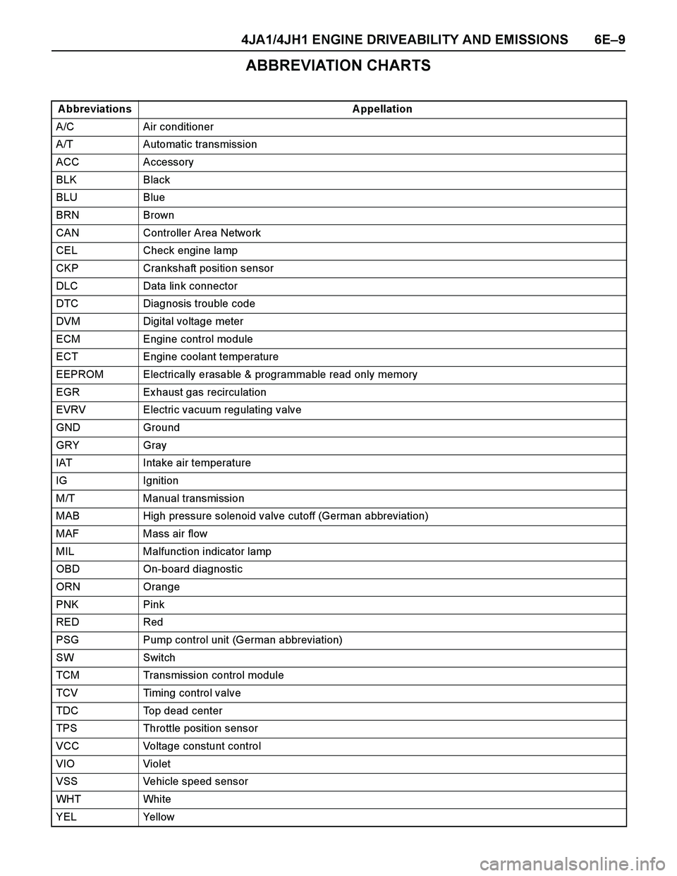
ABBREVIATION CHARTS
A bbreviations A ppellation
A/C Air conditioner
A/T Automatic transmission
ACC Accessory
BLK Black
BLU Blue
BRN Brown
CAN Controller Area Network
CEL Check engine lamp
CKP Crankshaft position sensor
DLC Data link connector
DTC Diagnosis trouble code
DVM Digital voltage meter
ECM Engine control module
ECT Engine coolant temperature
EEPROM Electrically erasable & programmable read only memory
EGR Ex haust gas recirculation
EVRV Electric vacuum regulating valve
GND Ground
GRY Gray
IAT Intake air temperature
IG Ignition
M/T Manual transmission
MAB High pressure solenoid valve cutoff (German abbreviation)
MAF Mass air flow
MIL Malfunction indicator lamp
OBD On-board diagnostic
ORN Orange
PNK Pink
RED Red
PSG Pump control unit (German abbreviation)
SW Switch
TCM Transmission control module
TCV Timing control valve
TDC Top dead center
TPS Throttle position sensor
VCC Voltage constunt control
VIO Violet
VSS Vehicle speed sensor
WHT Whi te
YEL Yellow
Page 1385 of 4264

4JA1/4JH1 ENGINE DRIVEABILITY AND EMISSIONS 6E–13
(1) Engine Control Module (ECM)
(1) Engine Coolant Temperature (ECT) Sensor
(2) Thermo Unit for Water Temperature Gauge
(1) Vehicle Speed Sensor (VSS)
21
(1) EGR EVRV
(2) To Vacuum Pump
(3) To EGR Valve
(1) Crankshaft Position (CKP) Sensor
(2) Clutch Housing
321
12
Page 1413 of 4264

4JA1/4JH1 ENGINE DRIVEABILITY AND EMISSIONS 6E–41
No. Connector face No. Connector face
C-118
A/C Resister & Neutral switchE-23
Gray Idle SW
C-123 E-41
Black Coolant temp sensor
C-124 E-44
Gray Vehicle speed sensor
E-3
Black Magnetic clutch AC COMPE-49
Gray Glow plug
E-6 E-51
Black Inhibiter switch
E-9 H-4
White Engine room ~ Mission
E-10
Silver Engine groundH-6
White Engine room ~ INST
E-11
Natural
green Neutral switchH-7
White Engine room ~ INST
E-12
Natural
green Neutral switchH-18
White Engine room ~ INST
E-22
Brown TPS 1 mainH-22
White Engine ~ Engine room C
Page 1427 of 4264

4JA1/4JH1 ENGINE DRIVEABILITY AND EMISSIONS 6E–55
75 75 No Conne ctio n - - - - - - - - -
76 76 No Conne ctio n - - - - - - - - -
77 77 No Conne ctio n - - - - - - - - -
78 78 No Conne ctio n - - - - - - - - -
79 79 No Conne ctio n - - - - - - - - -
80 80 No Conne ctio n - - - - - - - - -
81 81 No Conne ctio n - - - - - - - - -
82 82 No Conne ctio n - - - - - - - - -
83 83 Ma ss Air Flo w (MAF)
Se nso r Po wer SupplyWH T/
REDLess than
1VAppro x . 5V Co nnect DC V 83 92
84 84 Intake Air Tempera-
ture (IAT) Sensor Sig-
na lBLK/
BLULess than
1V0 deg. C: Approx. 3.6V / 20 deg. C:
Approx. 2.6V / 40 deg. C: Approx.
1.7V / 60 deg. C: 1.1V / 80 deg. C:
0.7VCo nnect DC V 84 92
85 85 No Conne ctio n - - - - - - - - -
86 86 No Conne ctio n - - - - - - - - -
87 87 Neutral Switch BLK/
WH TLess than
1VIn neutral: Less than 1V
Other than neutral: 10-14VCo nnect DC V 87 GND
88 88 Ma ss Air Flo w (MAF)
Se nso r SignalGRN/
REDLess than
1VAppro x . 1V Appro x .
1.8VApprox.
2.5VCo nnect DC V 88 92
89 89 Engine Coolant Tem-
perature (ECT) Sen-
so r S ig na lGRY Less than
1V0 deg. C: Approx. 4.4V / 20 deg. C:
Approx. 3.8V / 40 deg. C: Approx.
2.9V / 60 deg. C: 2.1V / 80 deg. C:
1.4VCo nnect DC V 89 93
90 90 CKP Se nso r Signal RED - - Appro x .
47Hz by
w a v e fo rm Approx.
134Hz by
wave form
or approx.
1.1VCo nnect AC V 90 98
91 91 CKP Senso r Output
To Pump Co ntrol Unit
(PSG) No.8PNK - - Appro x .
47Hz by
w a v e fo rm Approx.
134Hz by
wave form
or approx.
0.7VCo nnect AC V 91 GND
92 92 Ma ss Air Flo w (MAF)
Se nsor GroundBLK/
REDContinuity
with
gro und- - - Connect Ohm 92 GND
93 93 Engine Coolant Tem-
perature (ECT) Sen-
so r Gro undBLK/
PNKContinuity
with
gro und- - - Connect Ohm 93 GND
94 94 Glo w Relay BLK/
REDLess than
1VGlow system is operated: Less than
1 V
Glow system is not operated: 10 - 14VCo nnect DC V 94 GND
95 95 No Conne ctio n - - - - - - - - -
96 96 No Conne ctio n - - - - - - - - -
97 97 EGR EVRV BLK/
ORG- - Approx. 140Hz by wave
fo rm whe n EVRV is
operated----
98 98 CKP Se nsor Ground WHT Continuity
with
gro und- - - Connect Ohm 98 GND
99 99 CAN (Contro ller Are a
Ne two rk) to PSG No .1BLU--------
100 100 CAN (Contro ller Are a
Ne two rk) to PSG No .2YEL--------Signal or Continuity Tester Position
Pin
No. B/Box
No.Pin Function Wire
ColorKey SW
OffKey SW
OnEngine
IdleEngine
2000rpmECM
Connec-
tionRange (+) (-)
Page 1433 of 4264

4JA1/4JH1 ENGINE DRIVEABILITY AND EMISSIONS 6E–61
89 89 Engine Coolant Tem-
perature (ECT) Sen-
sor Signa lGRY Le ss
tha n 1V0 deg. C: Approx. 4.4V / 20 deg. C:
Approx. 3.8V / 40 deg. C: Approx.
2.9V / 60 deg. C: 2.1V / 80 deg. C:
1.4VCo nnect DC V 89 93
90 90 CKP Senso r Signal RED - - Approx .
47Hz by
wave
form Approx.
134Hz by
wave
fo rm or
approx.
1.1VCo nnect AC V 90 98
91 91 CKP Sensor Output
To Pump Contro l Unit
(PSG) No.8PNK - - Approx .
47Hz by
wave
form Approx.
134Hz by
wave
fo rm or
approx.
0.7VCo nnect AC V 91 GND
92 92 Ma ss Air Flow (MAF)
Se nso r Gro undBLK/
REDCo ntinu-
ity with
ground- - - Connect Ohm 92 GND
93 93 Engine Coolant Tem-
perature (ECT) Sen-
so r & Ma nifo ld
Pressure Sensor
GroundBLK/
PNKCo ntinu-
ity with
ground- - - Connect Ohm 93 GND
94 94 Glo w Re la y BLK/
REDLe ss
tha n 1VGlow system is operated: Less than
1 V
Glow system is not operated: 10 -
14VCo nnect DC V 94 GND
9595No Connection---------
96 96 Turbo charge r Wa ste-
ga te Contro l EVRVBRW/
RED- - Wav e form - - - -
97 97 EGR EVRV BLK/
ORG- - Appro x. 140Hz by
wa ve fo rm whe n
EVRV is operated- ---
98 98 CKP Se nso r Ground WHT Co ntinu-
ity with
ground- - - Connect Ohm 98 GND
99 99 CAN (Contro lle r Area
Ne two rk) to PSG
No .1BLU--------
100 100 CAN (Contro lle r Area
Ne two rk) to PSG
No .2YEL--------
101 101 CKP Senso r Shie ld
LineBLK Co ntinu-
ity with
ground- - - Connect Ohm 101 GND
102102No Connection---------
103103No Connection---------
104104No Connection---------
105 105 Solenoid Valve Shut
Off (MAB) Output
Signa l to PSG No .5ORG --------Signal or Continuity Tester Position
Pin
No. B/
Box
No.Pin Function Wire
ColorKey SW
OffKey SW
OnEngine
IdleEngine
2000rpmECM
Connec-
tionRan
ge(+) (-)
Page 1439 of 4264
4JA1/4JH1 ENGINE DRIVEABILITY AND EMISSIONS 6E–67
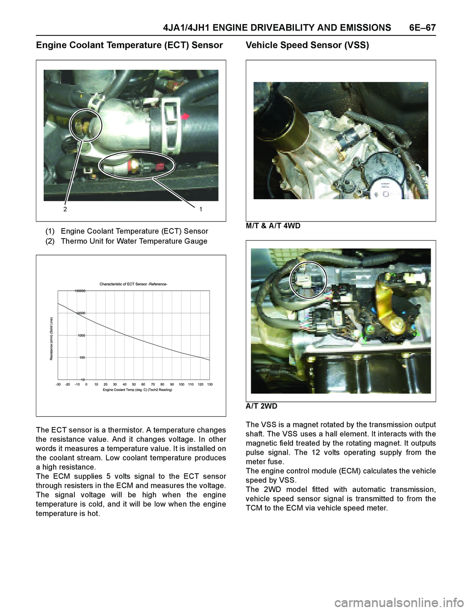
Engine Coolant Temperature (ECT) Sensor
The ECT sensor is a thermistor. A temperature changes
the resistance value. And it changes voltage. In other
words it measures a temperature value. It is installed on
the coolant stream. Low coolant temperature produces
a high resistance.
The ECM supplies 5 volts signal to the ECT sensor
through resisters in the ECM and measures the voltage.
The signal voltage will be high when the engine
temperature is cold, and it will be low when the engine
temperature is hot.
Vehicle Speed Sensor (VSS)
M/T & A /T 4WD
A/T 2WD
The VSS is a magnet rotated by the transmission output
shaft. The VSS uses a hall element. It interacts with the
magnetic field treated by the rotating magnet. It outputs
pulse signal. The 12 volts operating supply from the
meter fuse.
The engine control module (ECM) calculates the vehicle
speed by VSS.
The 2WD model fitted with automatic transmission,
vehicle speed sensor signal is transmitted to from the
TCM to the ECM via vehicle speed meter. (1) Engine Coolant Temperature (ECT) Sensor
(2) Thermo Unit for Water Temperature Gauge
12
Characteristic of ECT Sensor -Reference-
10 100 1000 10000 100000
-30 -20 -10 0 10 20 30 40 50 60 70 80 90 100 110 120 130
Engine Coolant Temp (deg. C) (Tech2 Reading)
Resistance (ohm) (Solid Line)
Page 1440 of 4264

6E–68 4JA1/4JH1 ENGINE DRIVEABILITY AND EMISSIONS
GENERAL DESCRIPTION FOR EGR
(EXHAUST GAS RE-CIRCULATION)
The 4JA1-TC & 4JH1-TC engine with Euro 3 regulation
is equipped with the EGR cooler. The EGR cooler
reduces the temperature of the air being drawn into the
engine and the combustion temperature. This results in
reducing nitrogen ox ide (Nox ) emissions. The 4JH1-TC
engine ex cept Euro 3 regulation, it does not have EGR
cooler. It has steel EGR pipe instead of the cooler.
The amount of EGR is controlled by EVRV (electrical
vacuum regulating valve) via the engine control module
(ECM) command signal depends on the following
inputs.
Engine speed
Injection quantity
Mass air flow
Intake air temperature
Coolant temperature
Barometric pressure (1) EGR Valve
(2) EGR Cooler (Euro 3) / EGR Pipe (Except Euro
3)
(3) Intercooler
(4) Intake Manifold
(5) Ex haust Manifold
(6) Waste Gate
(7) Fresh Air
(8) Ex haust Gas
(9) Turbocharger
123
(1) To EGR Valve
(2) From Vacuum Pump
(3) EGR EVRV
(4) EGR Cooler
(5) Thermo Valve
(6) EGR Valve
4 5 6
Page 1447 of 4264
4JA1/4JH1 ENGINE DRIVEABILITY AND EMISSIONS 6E–75
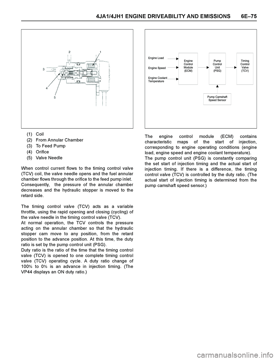
When control current flows to the timing control valve
(TCV) coil, the valve needle opens and the fuel annular
chamber flows through the orifice to the feed pump inlet.
Consequently, the pressure of the annular chamber
decreases and the hydraulic stopper is moved to the
retard side.
The timing control valve (TCV) acts as a variable
throttle, using the rapid opening and closing (cycling) of
the valve needle in the timing control valve (TCV).
At normal operation, the TCV controls the pressure
acting on the annular chamber so that the hydraulic
stopper cam move to any position, from the retard
position to the advance position. At this time, the duty
ratio is set by the pump control unit (PSG).
Duty ratio is the ratio of the time that the timing control
valve (TCV) is opened to one complete timing control
valve (TCV) operating cycle. A duty ratio change of
100% to 0% is an advance in injection timing. (The
VP44 displays an ON duty ratio.)The engine control module (ECM) contains
characteristic maps of the start of injection,
corresponding to engine operating conditions (engine
load, engine speed and engine coolant temperature).
The pump control unit (PSG) is constantly comparing
the set start of injection timing and the actual start of
injection timing. If there is a difference, the timing
control valve (TCV) is controlled by the duty ratio. (The
actual start of injection timing is determined from the
pump camshaft speed sensor.) (1) Coil
(2) From Annular Chamber
(3) To Feed Pump
(4) Orifice
(5) Valve Needle
Engine Load
Engine Speed
Engine Coolant
TemperatureEngine
Control
Module
(ECM)Pump
Control
Unit
(PSG)
Pump Camshaft
Speed Sensor
Timing
Control
Valve
(TCV)
Page 1460 of 4264
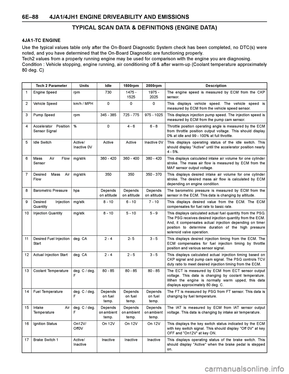
6E–88 4JA1/4JH1 ENGINE DRIVEABILITY AND EMISSIONS
TYPICAL SCAN DATA & DEFINITIONS (ENGINE DATA)
4JA 1-TC ENGINE
Use the typical values table only after the On-Board Diagnostic System check has been completed, no DTC(s) were
noted, and you have determined that the On-Board Diagnostic are functioning properly.
Tech2 values from a properly running engine may be used for comparison with the engine you are diagnosing.
Condition : Vehicle stopping, engine running, air conditioning off & after warm-up (Coolant temperature approx imately
80 deg. C)
Tech 2 Parameter Units Idle 1500rpm 2000rpm Description
1 Engine Speed rpm 730 1475 -
15251975 -
2025The engine speed is measured by ECM from the CKP
se nso r.
2 Vehicle Speed km/h / MPH 0 0 0 This displays vehicle speed. The vehicle speed is
measured by ECM from the vehicle speed sensor.
3 Pump Spe ed rpm 345 - 385 725 - 775 975 - 1025 This displa ys injectio n pump spe ed. The inje ction spe ed is
measured by ECM from the pump cam sensor.
4 Accelerator Position
Sensor Signal% 0 4 - 6 6 - 8 Throttle position operating angle is measured by the ECM
fro m throttle po sition o utput v olta ge . This sho uld display
0% a t idle a nd 99 - 100% a t full thro ttle .
5 Idle Switch Activ e /
Inactive 0VActive Active Inactive 0V This displays operating status of the idle switch. This
should display "Active" until the accelerator position nearly
4 - 5%.
6 Mass Air Flow
Sensormg/strk 380 - 420 360 - 400 380 - 420 This displays calculated intake air volume for one cylinder
stroke. The mass air flow is measured by ECM from the
MAF sensor output voltage.
7 Desire d Ma ss Air
Flo wmg/strk 350 350 350 - 370 This displays desired intake air volume for one cylinder
stroke. The desired mass air flow is calculated by ECM
de pe nding on engine conditio n.
8 Baro metric Pre ssure hpa De pe nds
on altitudeDe pe nds
o n a ltitudeDe pe nds
on altitudeThe ba rome tric pre ssure is mea sure d by ECM from the
sensor in the ECM. This data is changing by altitude.
9 Desired Injection
Qua ntitymg/stk 8 - 10 6 - 10 7 - 10 This displays desired value from the ECM. The ECM
co mpe nsates fo r fue l ra te to ba sic ra te.
10 Injection Qua ntity mg/stk 8 - 10 5 - 10 5 - 9 This displa y s ca lculated a ctua l fue l qua ntity from the PSG.
The PSG receives desired injection quantity from the ECM.
And, it compensates actual injection depending on timer
po sitio n to de termine duration o f the high pre ssure
solenoid valve operation.
11 Desire d Fuel Injection
St a r tde g. CA 2 - 4 2- 5 3 - 5 This display s de sired injection timing from the ECM. The
ECM compensates for fuel injection timing by throttle
position and various sensor signal.
12 Actua l Injectio n Sta rt de g. CA 2 - 4 2 - 5 3 - 5 This display s ca lculate d a ctua l inje ctio n timing ba se d o n
CKP signa l a nd pump ca m signal. The PSG controls TCV
duty ra tio to mee t desired inje ctio n timing from the ECM.
13 Coolant Temperature deg. C / deg.
F80 - 85 80 - 85 80 - 85 The ECT is measured by ECM from ECT sensor output
voltage. This data is changing by coolant temperature.
When the engine is normally warm upped, this data
displays approximately 80 deg. C.
14 Fuel Temperature deg. C / deg.
FDe pe nds
on fuel
temp.De pe nds
on fuel
te mp.De pe nds
on fuel
te mp.The FT is measured by PSG from FT sensor. This data is
changing by fuel temperature.
15 Inta ke Air
Temperaturedeg. C / deg.
FDe pe nds
on ambient
temp.De pe nds
on ambient
te mp.De pe nds
on ambient
te mp.The IAT is measured by ECM from IAT sensor output
voltage. This data is changing by intake air temperature.
16 Ignition Status On12V/
Off0VOn 12V On 12V On 12V This displays the key switch status indicated by the ECM
with key switch signal. This should display "Off 0V" at key
OFF and "On12V" at key ON.
17 Brake Switch 1 Active/
InactiveInactive Inactive Inactive This displays operating status of the brake switch. This
should display "Active" when the brake pedal is stepped
on.