park assist ISUZU TF SERIES 2004 Workshop Manual
[x] Cancel search | Manufacturer: ISUZU, Model Year: 2004, Model line: TF SERIES, Model: ISUZU TF SERIES 2004Pages: 4264, PDF Size: 72.63 MB
Page 338 of 4264

5A-22 BRAKE CONTROL SYSTEM
“ABS” Warning Lamp
When ABS and trouble occurs to actuate “ABS”
warning lamp, the trouble code corresponding to the
trouble is stored in the EHCU. Only ordinary brake is
available with ABS being unactuated. Even when
“ABS” warning lamp is actuated, if the starter switch is
set ON after setting it OFF once, the EHCU checks up
on the entire system and, if there is no abnormality,
judges ABS to work currently and the warning lamp is lit
normally even though the trouble code is stored.
NOTE: Illumination of the “ABS” warning lamp indicates
that anti-lock braking is no longer available. Power
assisted braking without anti-lock control is still
available.
Normal Operation
“ABS ” Warning Lamp
When the ignition is first moved from “OFF” to “RUN”,
the amber “ABS” warning lamp will turn “ON”. The
“ABS” warning lamp will turn “ON” during engine
starting and will usually stay “ON” for approximately
three seconds after the ignition switch is returned to the
“ON” position. The warning lamp should remain “OFF”
at all other times.
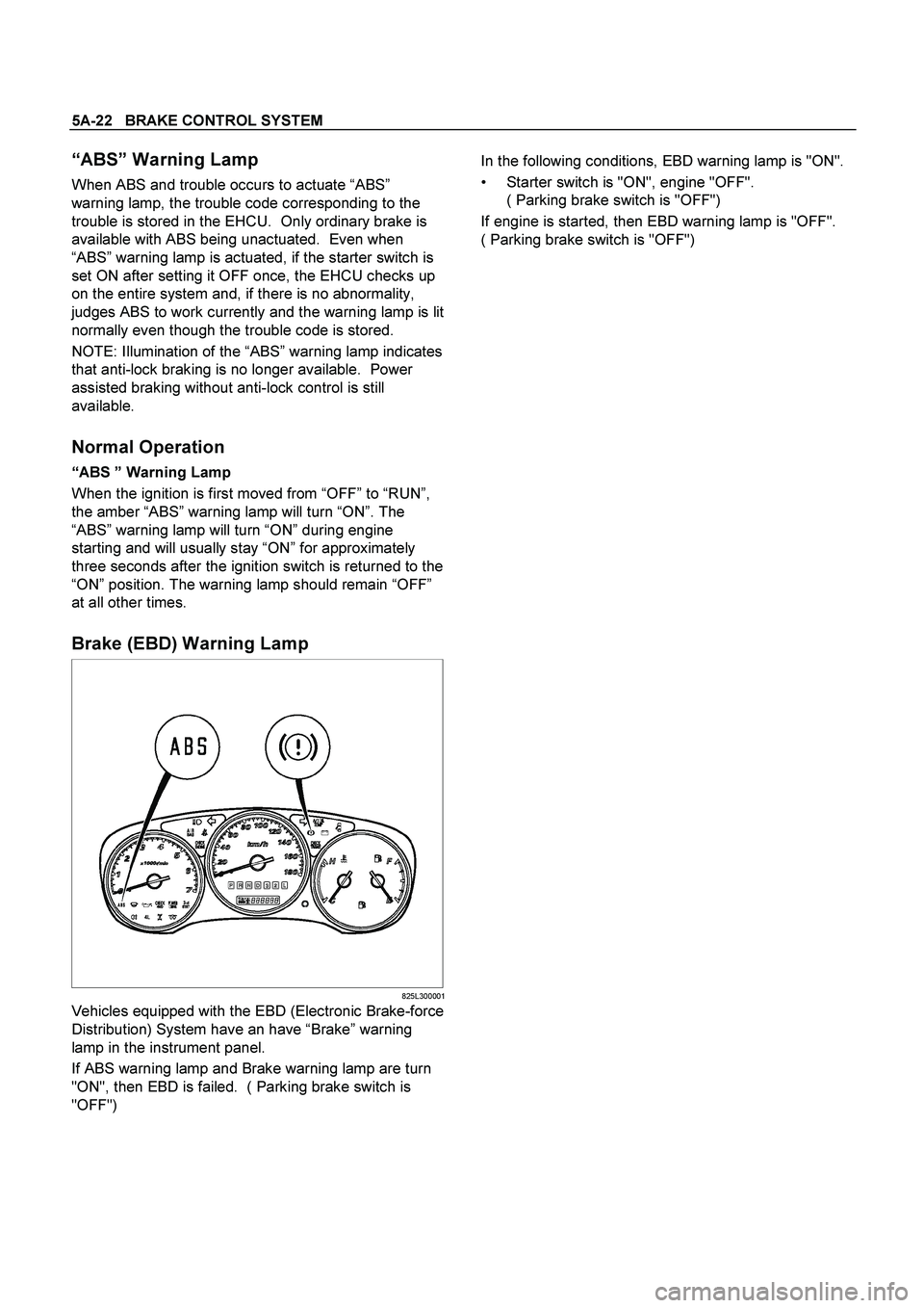
Brake (EBD) Warning Lamp
825L300001
Vehicles equipped with the EBD (Electronic Brake-force
Distribution) System have an have “Brake” warning
lamp in the instrument panel.
If ABS warning lamp and Brake warning lamp are turn
"ON", then EBD is failed. ( Parking brake switch is
"OFF")
In the following conditions, EBD warning lamp is "ON".
Starter switch is "ON", engine "OFF".
( Parking brake switch is "OFF")
If engine is started, then EBD warning lamp is "OFF".
( Parking brake switch is "OFF")
Page 2246 of 4264

6E-250 3.5L ENGINE DRIVEABILITY AND EMISSIONS
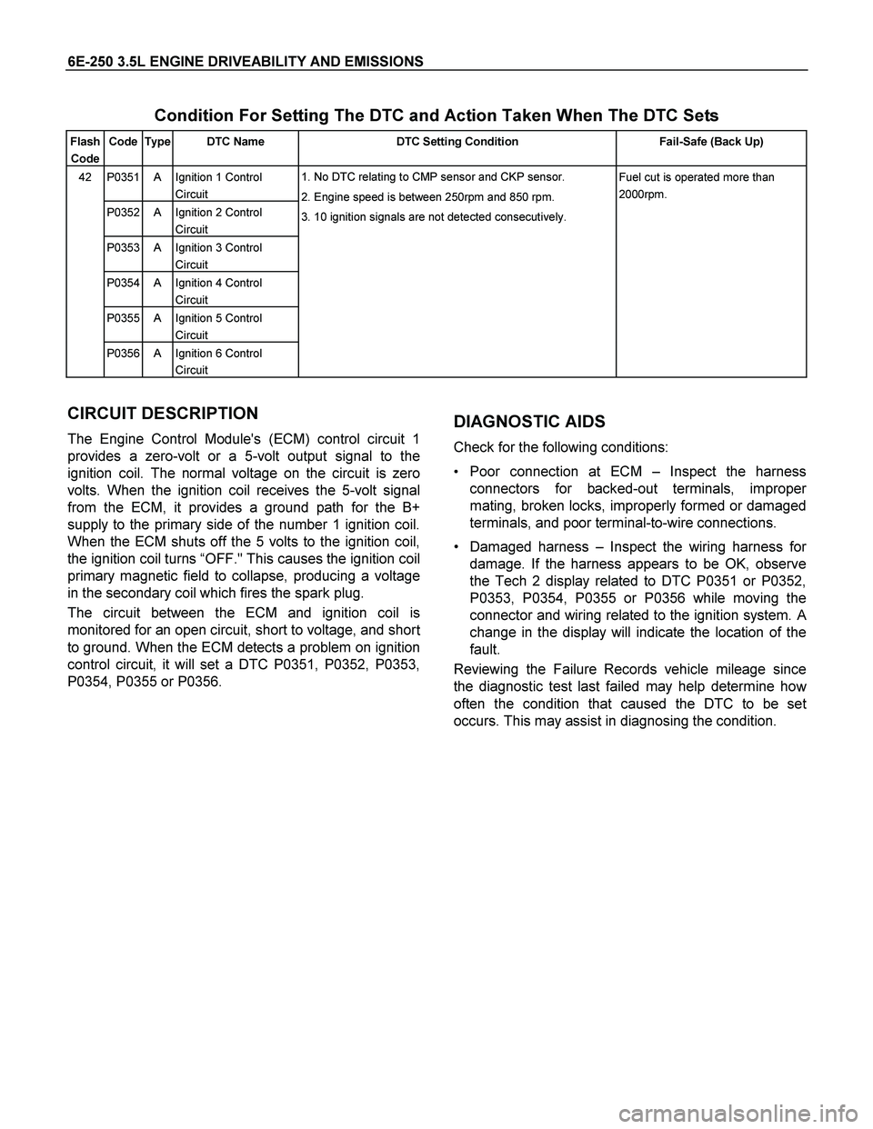
Condition For Setting The DTC and Action Taken When The DTC Sets
Flash
Code Code Type DTC Name DTC Setting Condition Fail-Safe (Back Up)
P0351 A Ignition 1 Control
Circuit
P0352 A Ignition 2 Control
Circuit
P0353 A Ignition 3 Control
Circuit
P0354 A Ignition 4 Control
Circuit
P0355 A Ignition 5 Control
Circuit
42
P0356 A Ignition 6 Control
Circuit 1. No DTC relating to CMP sensor and CKP sensor.
2. Engine speed is between 250rpm and 850 rpm.
3. 10 ignition signals are not detected consecutively. Fuel cut is operated more than
2000rpm.
CIRCUIT DESCRIPTION
The Engine Control Module's (ECM) control circuit 1
provides a zero-volt or a 5-volt output signal to the
ignition coil. The normal voltage on the circuit is zero
volts. When the ignition coil receives the 5-volt signal
from the ECM, it provides a ground path for the B+
supply to the primary side of the number 1 ignition coil.
When the ECM shuts off the 5 volts to the ignition coil,
the ignition coil turns “OFF." This causes the ignition coil
primary magnetic field to collapse, producing a voltage
in the secondary coil which fires the spark plug.
The circuit between the ECM and ignition coil is
monitored for an open circuit, short to voltage, and shor
t
to ground. When the ECM detects a problem on ignition
control circuit, it will set a DTC P0351, P0352, P0353,
P0354, P0355 or P0356.
DIAGNOSTIC AIDS
Check for the following conditions:
Poor connection at ECM – Inspect the harness
connectors for backed-out terminals, imprope
r
mating, broken locks, improperly formed or damaged
terminals, and poor terminal-to-wire connections.
Damaged harness –Inspect the wiring harness fo
r
damage. If the harness appears to be OK, observe
the Tech 2 display related to DTC P0351 or P0352,
P0353, P0354, P0355 or P0356 while moving the
connector and wiring related to the ignition system.
A
change in the display will indicate the location of the
fault.
Reviewing the Failure Records vehicle mileage since
the diagnostic test last failed may help determine ho
w
often the condition that caused the DTC to be set
occurs. This may assist in diagnosing the condition.