mass air flow ISUZU TF SERIES 2004 Workshop Manual
[x] Cancel search | Manufacturer: ISUZU, Model Year: 2004, Model line: TF SERIES, Model: ISUZU TF SERIES 2004Pages: 4264, PDF Size: 72.63 MB
Page 1373 of 4264
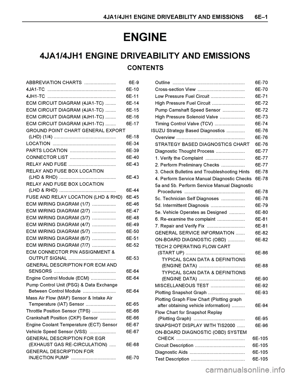
4JA1/4JH1 ENGINE DRIVEABILITY AND EMISSIONS 6E–1
ENGINE
CONTENTS
4JA1/4JH1 ENGINE DRIVEABILITY AND EMISSIONS
ABBREVIATION CHARTS ........................ 6E-9
4JA1-TC .................................................... 6E-10
4JH1-TC .................................................... 6E-11
ECM CIRCUIT DIAGRAM (4JA1-TC) ........ 6E-14
ECM CIRCUIT DIAGRAM (4JA1-TC) ........ 6E-15
ECM CIRCUIT DIAGRAM (4JH1-TC) ........ 6E-16
ECM CIRCUIT DIAGRAM (4JH1-TC) ........ 6E-17
GROUND POINT CHART GENERAL EXPORT
(LHD) (1/4) ............................................... 6E-18
LOCATION ................................................ 6E-34
PARTS LOCATION ................................... 6E-39
CONNECTOR LIST ................................... 6E-40
RELAY AND FUSE .................................... 6E-43
RELAY AND FUSE BOX LOCATION
(LHD & RHD) ........................................... 6E-43
RELAY AND FUSE BOX LOCATION
(LHD & RHD) ........................................... 6E-44
FUSE AND RELAY LOCATION (LHD & RHD) 6E-45
ECM WIRING DIAGRAM (1/7) .................. 6E-46
ECM WIRING DIAGRAM (2/7) .................. 6E-47
ECM WIRING DIAGRAM (3/7) .................. 6E-48
ECM WIRING DIAGRAM (4/7) .................. 6E-49
ECM WIRING DIAGRAM (5/7) .................. 6E-50
ECM WIRING DIAGRAM (6/7) .................. 6E-51
ECM WIRING DIAGRAM (7/7) .................. 6E-52
ECM CONNECTOR PIN ASSIGNMENT &
OUTPUT SIGNAL .................................... 6E-53
GENERAL DESCRIPTION FOR ECM AND
SENSORS ............................................... 6E-64
Engine Control Module (ECM) ................... 6E-64
Pump Control Unit (PSG) & Data Ex change
Between Control Module ......................... 6E-64
Mass Air Flow (MAF) Sensor & Intake Air
Temperature (IAT) Sensor ....................... 6E-65
Throttle Position Sensor (TPS) .................. 6E-66
Crankshaft Position (CKP) Sensor ............ 6E-66
Engine Coolant Temperature (ECT) Sensor 6E-67
Vehicle Speed Sensor (VSS) .................... 6E-67
GENERAL DESCRIPTION FOR EGR
(EXHAUST GAS RE-CIRCULATION) ..... 6E-68
GENERAL DESCRIPTION FOR
INJECTION PUMP .................................. 6E-70Outline ....................................................... 6E-70
Cross-section View .................................... 6E-70
Low Pressure Fuel Circuit .......................... 6E-71
High Pressure Fuel Circuit ......................... 6E-72
Pump Camshaft Speed Sensor ................. 6E-72
High Pressure Solenoid Valve ................... 6E-73
Timing Control Valve (TCV) ....................... 6E-74
ISUZU Strategy Based Diagnostics .............. 6E-76
Overview .................................................... 6E-76
STRATEGY BASED DIAGNOSTICS CHART 6E-76
Diagnostic Thought Process ...................... 6E-77
1. Verify the Complaint .............................. 6E-77
2. Perform Preliminary Checks .................. 6E-77
3. Check Bulletins and Troubleshooting Hints 6E-78
4. Perform Service Manual Diagnostic Checks 6E-78
5a and 5b. Perform Service Manual Diagnostic
Procedures .............................................. 6E-78
5c. Technician Self Diagnoses .................. 6E-78
5d. Intermittent Diagnosis .......................... 6E-79
5e. Vehicle Operates as Designed ............ 6E-80
6. Re-examine the complaint ..................... 6E-81
7. Repair and Verify Fix ............................. 6E-81
GENERAL SERVICE INFORMATION ....... 6E-82
ON-BOARD DIAGNOSTIC (OBD) ............. 6E-82
TECH 2 OPERATING FLOW CART
(START UP) ............................................. 6E-86
TYPICAL SCAN DATA & DEFINITIONS
(ENGINE DATA) ................................... 6E-88
TYPICAL SCAN DATA & DEFINITIONS
(ENGINE DATA) ................................... 6E-90
MISCELLANEOUS TEST .......................... 6E-92
Plotting Snapshot Graph ............................ 6E-93
Plotting Graph Flow Chart (Plotting graph
after obtaining vehicle information) .......... 6E-94
Flow Chart for Snapshot Replay
(Plotting Graph) ....................................... 6E-95
SNAPSHOT DISPLAY WITH TIS2000 ...... 6E-96
ON-BOARD DIAGNOSTIC (OBD) SYSTEM
CHECK .................................................... 6E-105
Circuit Description ...................................... 6E-105
Diagnostic Aids .......................................... 6E-105
Test Description ......................................... 6E-105
Page 1374 of 4264
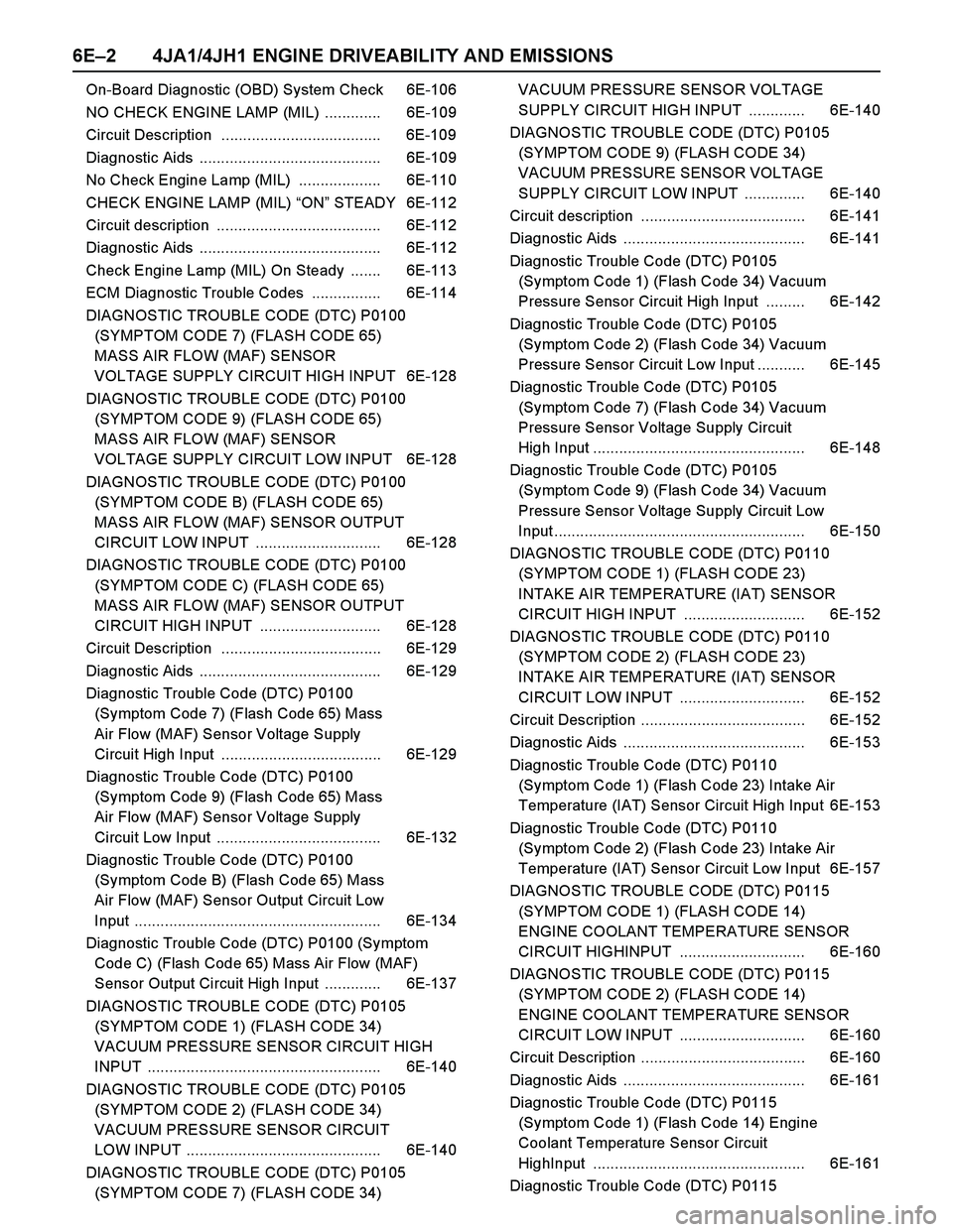
6E–2 4JA1/4JH1 ENGINE DRIVEABILITY AND EMISSIONS
On-Board Diagnostic (OBD) System Check 6E-106
NO CHECK ENGINE LAMP (MIL) ............. 6E-109
Circuit Description ..................................... 6E-109
Diagnostic Aids .......................................... 6E-109
No Check Engine Lamp (MIL) ................... 6E-110
CHECK ENGINE LAMP (MIL) “ON” STEADY 6E-112
Circuit description ...................................... 6E-112
Diagnostic Aids .......................................... 6E-112
Check Engine Lamp (MIL) On Steady ....... 6E-113
ECM Diagnostic Trouble Codes ................ 6E-114
DIAGNOSTIC TROUBLE CODE (DTC) P0100
(SYMPTOM CODE 7) (FLASH CODE 65)
MASS AIR FLOW (MAF) SENSOR
VOLTAGE SUPPLY CIRCUIT HIGH INPUT 6E-128
DIAGNOSTIC TROUBLE CODE (DTC) P0100
(SYMPTOM CODE 9) (FLASH CODE 65)
MASS AIR FLOW (MAF) SENSOR
VOLTAGE SUPPLY CIRCUIT LOW INPUT 6E-128
DIAGNOSTIC TROUBLE CODE (DTC) P0100
(SYMPTOM CODE B) (FLASH CODE 65)
MASS AIR FLOW (MAF) SENSOR OUTPUT
CIRCUIT LOW INPUT ............................. 6E-128
DIAGNOSTIC TROUBLE CODE (DTC) P0100
(SYMPTOM CODE C) (FLASH CODE 65)
MASS AIR FLOW (MAF) SENSOR OUTPUT
CIRCUIT HIGH INPUT ............................ 6E-128
Circuit Description ..................................... 6E-129
Diagnostic Aids .......................................... 6E-129
Diagnostic Trouble Code (DTC) P0100
(Symptom Code 7) (Flash Code 65) Mass
Air Flow (MAF) Sensor Voltage Supply
Circuit High Input ..................................... 6E-129
Diagnostic Trouble Code (DTC) P0100
(Symptom Code 9) (Flash Code 65) Mass
Air Flow (MAF) Sensor Voltage Supply
Circuit Low Input ...................................... 6E-132
Diagnostic Trouble Code (DTC) P0100
(Symptom Code B) (Flash Code 65) Mass
Air Flow (MAF) Sensor Output Circuit Low
Input ......................................................... 6E-134
Diagnostic Trouble Code (DTC) P0100 (Symptom
Code C) (Flash Code 65) Mass Air Flow (MAF)
Sensor Output Circuit High Input ............. 6E-137
DIAGNOSTIC TROUBLE CODE (DTC) P0105
(SYMPTOM CODE 1) (FLASH CODE 34)
VACUUM PRESSURE SENSOR CIRCUIT HIGH
INPUT ...................................................... 6E-140
DIAGNOSTIC TROUBLE CODE (DTC) P0105
(SYMPTOM CODE 2) (FLASH CODE 34)
VACUUM PRESSURE SENSOR CIRCUIT
LOW INPUT ............................................. 6E-140
DIAGNOSTIC TROUBLE CODE (DTC) P0105
(SYMPTOM CODE 7) (FLASH CODE 34) VACUUM PRESSURE SENSOR VOLTAGE
SUPPLY CIRCUIT HIGH INPUT ............. 6E-140
DIAGNOSTIC TROUBLE CODE (DTC) P0105
(SYMPTOM CODE 9) (FLASH CODE 34)
VACUUM PRESSURE SENSOR VOLTAGE
SUPPLY CIRCUIT LOW INPUT .............. 6E-140
Circuit description ...................................... 6E-141
Diagnostic Aids .......................................... 6E-141
Diagnostic Trouble Code (DTC) P0105
(Symptom Code 1) (Flash Code 34) Vacuum
Pressure Sensor Circuit High Input ......... 6E-142
Diagnostic Trouble Code (DTC) P0105
(Symptom Code 2) (Flash Code 34) Vacuum
Pressure Sensor Circuit Low Input ........... 6E-145
Diagnostic Trouble Code (DTC) P0105
(Symptom Code 7) (Flash Code 34) Vacuum
Pressure Sensor Voltage Supply Circuit
High Input ................................................. 6E-148
Diagnostic Trouble Code (DTC) P0105
(Symptom Code 9) (Flash Code 34) Vacuum
Pressure Sensor Voltage Supply Circuit Low
Input .......................................................... 6E-150
DIAGNOSTIC TROUBLE CODE (DTC) P0110
(SYMPTOM CODE 1) (FLASH CODE 23)
INTAKE AIR TEMPERATURE (IAT) SENSOR
CIRCUIT HIGH INPUT ............................ 6E-152
DIAGNOSTIC TROUBLE CODE (DTC) P0110
(SYMPTOM CODE 2) (FLASH CODE 23)
INTAKE AIR TEMPERATURE (IAT) SENSOR
CIRCUIT LOW INPUT ............................. 6E-152
Circuit Description ...................................... 6E-152
Diagnostic Aids .......................................... 6E-153
Diagnostic Trouble Code (DTC) P0110
(Symptom Code 1) (Flash Code 23) Intake Air
Temperature (IAT) Sensor Circuit High Input 6E-153
Diagnostic Trouble Code (DTC) P0110
(Symptom Code 2) (Flash Code 23) Intake Air
Temperature (IAT) Sensor Circuit Low Input 6E-157
DIAGNOSTIC TROUBLE CODE (DTC) P0115
(SYMPTOM CODE 1) (FLASH CODE 14)
ENGINE COOLANT TEMPERATURE SENSOR
CIRCUIT HIGHINPUT ............................. 6E-160
DIAGNOSTIC TROUBLE CODE (DTC) P0115
(SYMPTOM CODE 2) (FLASH CODE 14)
ENGINE COOLANT TEMPERATURE SENSOR
CIRCUIT LOW INPUT ............................. 6E-160
Circuit Description ...................................... 6E-160
Diagnostic Aids .......................................... 6E-161
Diagnostic Trouble Code (DTC) P0115
(Symptom Code 1) (Flash Code 14) Engine
Coolant Temperature Sensor Circuit
HighInput ................................................. 6E-161
Diagnostic Trouble Code (DTC) P0115
Page 1380 of 4264
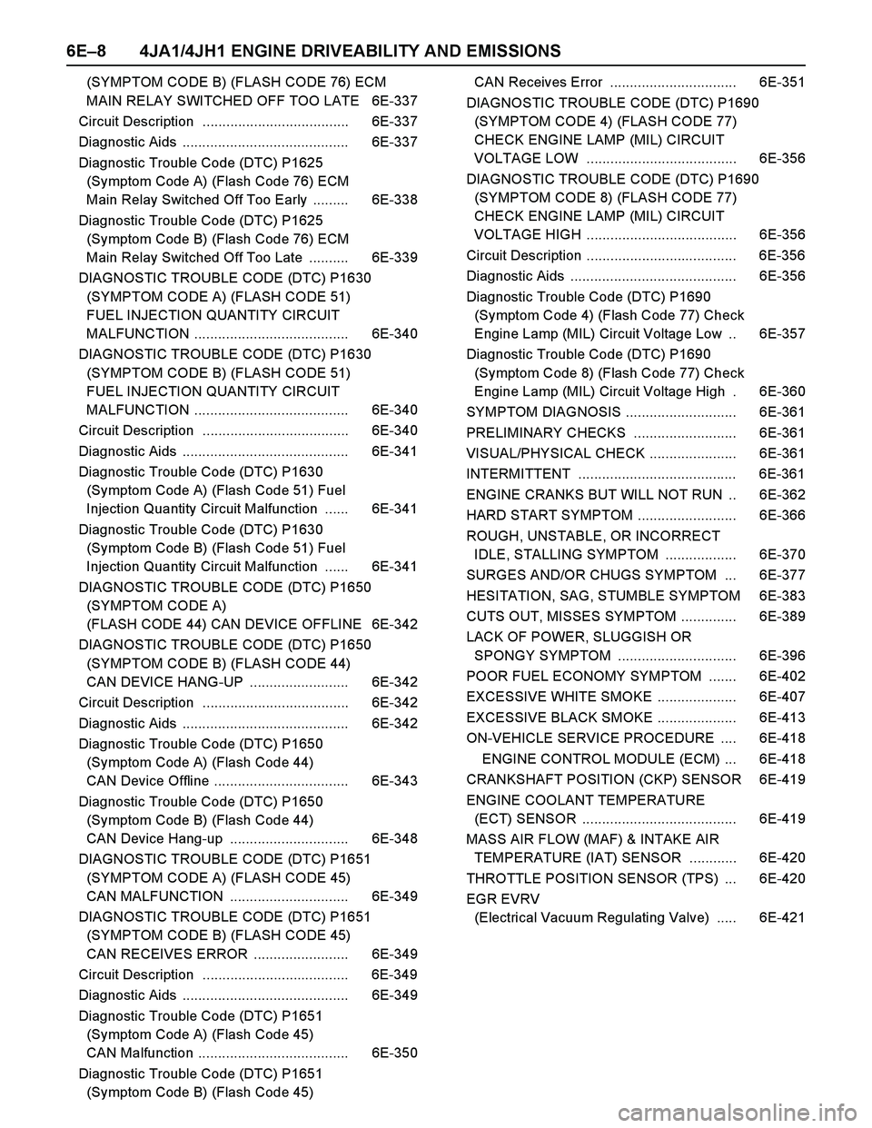
6E–8 4JA1/4JH1 ENGINE DRIVEABILITY AND EMISSIONS
(SYMPTOM CODE B) (FLASH CODE 76) ECM
MAIN RELAY SWITCHED OFF TOO LATE 6E-337
Circuit Description ..................................... 6E-337
Diagnostic Aids .......................................... 6E-337
Diagnostic Trouble Code (DTC) P1625
(Symptom Code A) (Flash Code 76) ECM
Main Relay Switched Off Too Early ......... 6E-338
Diagnostic Trouble Code (DTC) P1625
(Symptom Code B) (Flash Code 76) ECM
Main Relay Switched Off Too Late .......... 6E-339
DIAGNOSTIC TROUBLE CODE (DTC) P1630
(SYMPTOM CODE A) (FLASH CODE 51)
FUEL INJECTION QUANTITY CIRCUIT
MALFUNCTION ....................................... 6E-340
DIAGNOSTIC TROUBLE CODE (DTC) P1630
(SYMPTOM CODE B) (FLASH CODE 51)
FUEL INJECTION QUANTITY CIRCUIT
MALFUNCTION ....................................... 6E-340
Circuit Description ..................................... 6E-340
Diagnostic Aids .......................................... 6E-341
Diagnostic Trouble Code (DTC) P1630
(Symptom Code A) (Flash Code 51) Fuel
Injection Quantity Circuit Malfunction ...... 6E-341
Diagnostic Trouble Code (DTC) P1630
(Symptom Code B) (Flash Code 51) Fuel
Injection Quantity Circuit Malfunction ...... 6E-341
DIAGNOSTIC TROUBLE CODE (DTC) P1650
(SYMPTOM CODE A)
(FLASH CODE 44) CAN DEVICE OFFLINE 6E-342
DIAGNOSTIC TROUBLE CODE (DTC) P1650
(SYMPTOM CODE B) (FLASH CODE 44)
CAN DEVICE HANG-UP ......................... 6E-342
Circuit Description ..................................... 6E-342
Diagnostic Aids .......................................... 6E-342
Diagnostic Trouble Code (DTC) P1650
(Symptom Code A) (Flash Code 44)
CAN Device Offline .................................. 6E-343
Diagnostic Trouble Code (DTC) P1650
(Symptom Code B) (Flash Code 44)
CAN Device Hang-up .............................. 6E-348
DIAGNOSTIC TROUBLE CODE (DTC) P1651
(SYMPTOM CODE A) (FLASH CODE 45)
CAN MALFUNCTION .............................. 6E-349
DIAGNOSTIC TROUBLE CODE (DTC) P1651
(SYMPTOM CODE B) (FLASH CODE 45)
CAN RECEIVES ERROR ........................ 6E-349
Circuit Description ..................................... 6E-349
Diagnostic Aids .......................................... 6E-349
Diagnostic Trouble Code (DTC) P1651
(Symptom Code A) (Flash Code 45)
CAN Malfunction ...................................... 6E-350
Diagnostic Trouble Code (DTC) P1651
(Symptom Code B) (Flash Code 45) CAN Receives Error ................................ 6E-351
DIAGNOSTIC TROUBLE CODE (DTC) P1690
(SYMPTOM CODE 4) (FLASH CODE 77)
CHECK ENGINE LAMP (MIL) CIRCUIT
VOLTAGE LOW ...................................... 6E-356
DIAGNOSTIC TROUBLE CODE (DTC) P1690
(SYMPTOM CODE 8) (FLASH CODE 77)
CHECK ENGINE LAMP (MIL) CIRCUIT
VOLTAGE HIGH ...................................... 6E-356
Circuit Description ...................................... 6E-356
Diagnostic Aids .......................................... 6E-356
Diagnostic Trouble Code (DTC) P1690
(Symptom Code 4) (Flash Code 77) Check
Engine Lamp (MIL) Circuit Voltage Low .. 6E-357
Diagnostic Trouble Code (DTC) P1690
(Symptom Code 8) (Flash Code 77) Check
Engine Lamp (MIL) Circuit Voltage High . 6E-360
SYMPTOM DIAGNOSIS ............................ 6E-361
PRELIMINARY CHECKS .......................... 6E-361
VISUAL/PHYSICAL CHECK ...................... 6E-361
INTERMITTENT ........................................ 6E-361
ENGINE CRANKS BUT WILL NOT RUN .. 6E-362
HARD START SYMPTOM ......................... 6E-366
ROUGH, UNSTABLE, OR INCORRECT
IDLE, STALLING SYMPTOM .................. 6E-370
SURGES AND/OR CHUGS SYMPTOM ... 6E-377
HESITATION, SAG, STUMBLE SYMPTOM 6E-383
CUTS OUT, MISSES SYMPTOM .............. 6E-389
LACK OF POWER, SLUGGISH OR
SPONGY SYMPTOM .............................. 6E-396
POOR FUEL ECONOMY SYMPTOM ....... 6E-402
EXCESSIVE WHITE SMOKE .................... 6E-407
EXCESSIVE BLACK SMOKE .................... 6E-413
ON-VEHICLE SERVICE PROCEDURE .... 6E-418
ENGINE CONTROL MODULE (ECM) ... 6E-418
CRANKSHAFT POSITION (CKP) SENSOR 6E-419
ENGINE COOLANT TEMPERATURE
(ECT) SENSOR ....................................... 6E-419
MASS AIR FLOW (MAF) & INTAKE AIR
TEMPERATURE (IAT) SENSOR ............ 6E-420
THROTTLE POSITION SENSOR (TPS) ... 6E-420
EGR EVRV
(Electrical Vacuum Regulating Valve) ..... 6E-421
Page 1381 of 4264
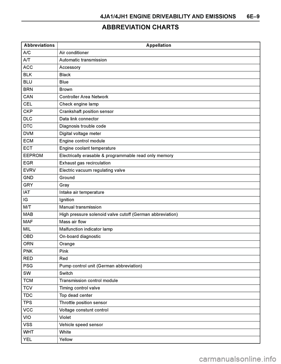
4JA1/4JH1 ENGINE DRIVEABILITY AND EMISSIONS 6E–9
ABBREVIATION CHARTS
A bbreviations A ppellation
A/C Air conditioner
A/T Automatic transmission
ACC Accessory
BLK Black
BLU Blue
BRN Brown
CAN Controller Area Network
CEL Check engine lamp
CKP Crankshaft position sensor
DLC Data link connector
DTC Diagnosis trouble code
DVM Digital voltage meter
ECM Engine control module
ECT Engine coolant temperature
EEPROM Electrically erasable & programmable read only memory
EGR Ex haust gas recirculation
EVRV Electric vacuum regulating valve
GND Ground
GRY Gray
IAT Intake air temperature
IG Ignition
M/T Manual transmission
MAB High pressure solenoid valve cutoff (German abbreviation)
MAF Mass air flow
MIL Malfunction indicator lamp
OBD On-board diagnostic
ORN Orange
PNK Pink
RED Red
PSG Pump control unit (German abbreviation)
SW Switch
TCM Transmission control module
TCV Timing control valve
TDC Top dead center
TPS Throttle position sensor
VCC Voltage constunt control
VIO Violet
VSS Vehicle speed sensor
WHT Whi te
YEL Yellow
Page 1382 of 4264
6E–10 4JA1/4JH1 ENGINE DRIVEABILITY AND EMISSIONS
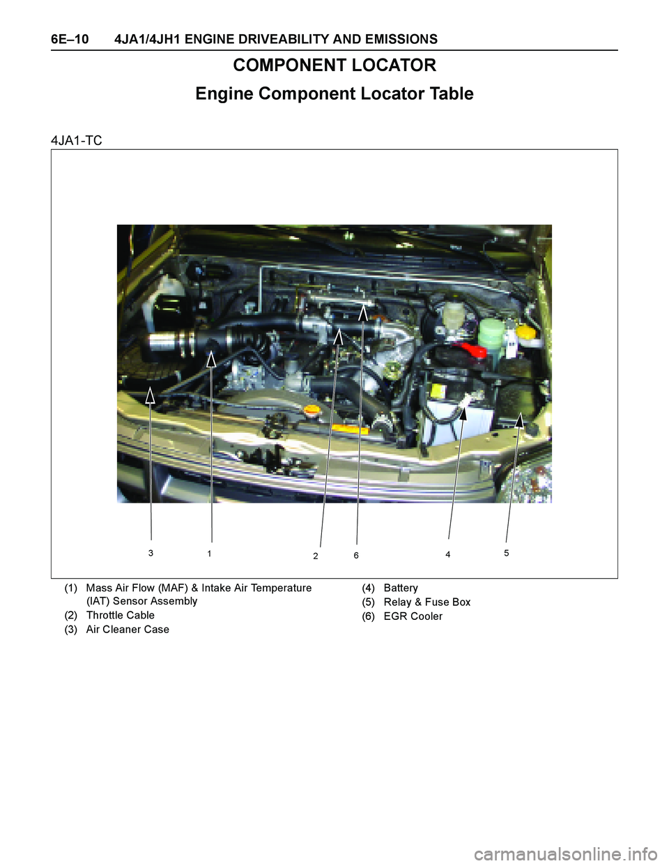
COMPONENT LOCATOR
Engine Component Locator Table
4JA1-TC
3
1
2645
(1) Mass Air Flow (MAF) & Intake Air Temperature
(IAT) Sensor Assembly
(2) Throttle Cable
(3) Air Cleaner Case(4) Battery
(5) Relay & Fuse Box
(6) EGR Cooler
Page 1383 of 4264
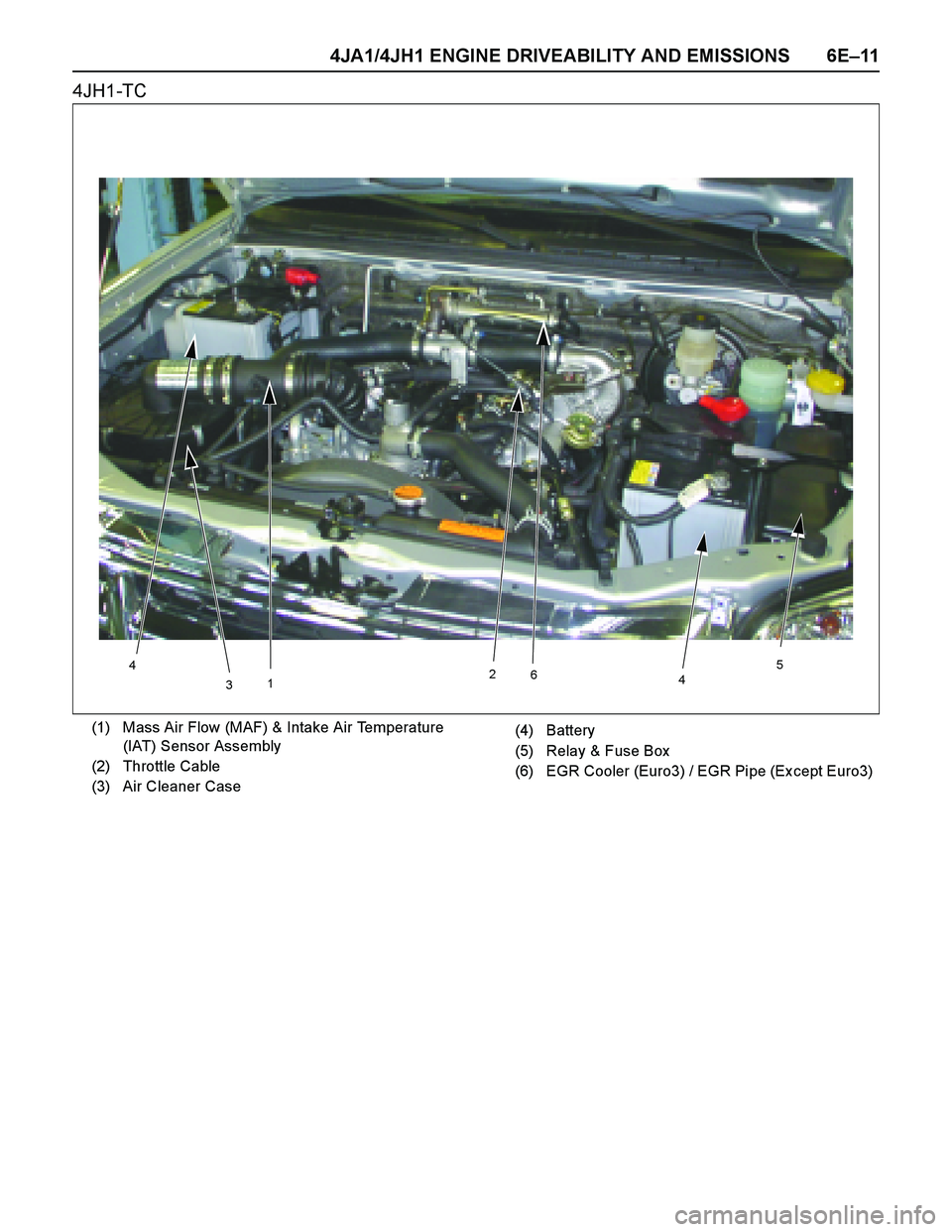
4JA1/4JH1 ENGINE DRIVEABILITY AND EMISSIONS 6E–11
4JH1-TC
312
6
45
4
(1) Mass Air Flow (MAF) & Intake Air Temperature
(IAT) Sensor Assembly
(2) Throttle Cable
(3) Air Cleaner Case(4) Battery
(5) Relay & Fuse Box
(6) EGR Cooler (Euro3) / EGR Pipe (Ex cept Euro3)
Page 1384 of 4264

6E–12 4JA1/4JH1 ENGINE DRIVEABILITY AND EMISSIONS
324
1
(1) Throttle Position Sensor (TPS)
(2) Pump Control Unit (PSG)(3) Injection Pump Assembly
(4) Fuel Filter (Ex cept Euro 3)
213
(1) Mass Air Flow (MAF) & Intake Air Temperature
(IAT) Sensor Assembly
(2) EGR EVRV(3) Air Cleaner Case
Page 1437 of 4264

4JA1/4JH1 ENGINE DRIVEABILITY AND EMISSIONS 6E–65
The following signals are ex changed via the CAN-bus:
From ECM to PSG
Desired injection quantity
Desired injection timing
Engine speed
From PSG to ECM
Fuel temperature
Pump speed
Cylinder identifier
Control pulse (actual injection quantity + actual
injection timing)
PSG status
Mass Air Flow (MAF) Sensor & Intake Air
Temperature (IAT) Sensor
The mass air flow (MAF) sensor is part of the intake air
system.
It is fitted between the air cleaner and turbocharger and
measure the mass air flowing into the engine.
The mass air flow (MAF) sensor uses a hot film element
to determine the amount of air flowing into the engine.
The mass air flow (MAF) sensor assembly consist of a
mass air flow (MAF) sensor element and an intake air
temperature sensor that are both ex posed to the air flow
to be measured.
The mass air flow (MAF) sensor element measures the
partial air mass through a measurement duct on the
sensor housing.
Using calibration, there is an ex trapolation to the entire
mass air flow to the engine.The IAT sensor is a thermistor. A temperature changes
the resistance value. And it changes voltage. In other
words it measures a temperature value. Low air
temperature produces a high resistance.
The ECM supplies 5 volts signal to the IAT sensor
through resisters in the ECM and measures the voltage.
The signal voltage will be high when the air temperature
is cold, and it will be low when the air temperature is
hot.
(1) Air Cleaner Case
(2) Mass Air Flow (MAF) & Intake Air Temperature
(IAT) Sensor
1 2
Characteristic of IAT Sensor -Reference-
10 100 1000 10000 100000
-30 -20 -10 0 10 20 30 40 50 60 70 80 90 100 110
Intake Air Temp. (deg. C) (Tech2 Reading)
Resistance (ohm) (Solid Line)
Page 1440 of 4264

6E–68 4JA1/4JH1 ENGINE DRIVEABILITY AND EMISSIONS
GENERAL DESCRIPTION FOR EGR
(EXHAUST GAS RE-CIRCULATION)
The 4JA1-TC & 4JH1-TC engine with Euro 3 regulation
is equipped with the EGR cooler. The EGR cooler
reduces the temperature of the air being drawn into the
engine and the combustion temperature. This results in
reducing nitrogen ox ide (Nox ) emissions. The 4JH1-TC
engine ex cept Euro 3 regulation, it does not have EGR
cooler. It has steel EGR pipe instead of the cooler.
The amount of EGR is controlled by EVRV (electrical
vacuum regulating valve) via the engine control module
(ECM) command signal depends on the following
inputs.
Engine speed
Injection quantity
Mass air flow
Intake air temperature
Coolant temperature
Barometric pressure (1) EGR Valve
(2) EGR Cooler (Euro 3) / EGR Pipe (Except Euro
3)
(3) Intercooler
(4) Intake Manifold
(5) Ex haust Manifold
(6) Waste Gate
(7) Fresh Air
(8) Ex haust Gas
(9) Turbocharger
123
(1) To EGR Valve
(2) From Vacuum Pump
(3) EGR EVRV
(4) EGR Cooler
(5) Thermo Valve
(6) EGR Valve
4 5 6
Page 1459 of 4264
4JA1/4JH1 ENGINE DRIVEABILITY AND EMISSIONS 6E–87
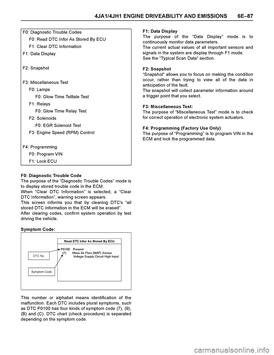
F0: Diagnostic Trouble Code
The purpose of the “Diagnostic Trouble Codes” mod e i s
to display stored trouble code in the ECM.
When “Clear DTC Information” is selected, a “Clear
DTC Information”, warning screen appears.
This screen informs you that by cleaning DTC's “all
stored DTC information in the ECM will be erased”.
After clearing codes, confirm system operation by test
driving the vehicle.
Symptom Code:
This number or alphabet means identification of the
malfunction. Each DTC includes plural symptoms, such
as DTC P0100 has four kinds of symptom code (7), (9),
(B) and (C). DTC chart (check procedure) is separated
depending on the symptom code.F1: Data Display
The purpose of the “Data Display” mode is to
continuously monitor data parameters.
The current actual values of all important sensors and
signals in the system are display through F1 mode.
See the “Typical Scan Data” section.
F2: Snapshot
“Snapshot” allows you to focus on making the condition
occur, rather than trying to view all of the data in
anticipation of the fault.
The snapshot will collect parameter information around
a trigger point that you select.
F3: Miscellaneous Test:
The purpose of “Miscellaneous Test” mode is to check
for correct operation of electronic system actuators.
F4: Programming (Factory Use Only)
The purpose of “Programming” is to program VIN in the
ECM and lock the programmed data. F0: Diagnostic Trouble Codes
F0: Read DTC Infor As Stored By ECU
F1: Clear DTC Information
F1: Data Display
F2: Snapshot
F3: Miscellaneous Test
F0: Lamps
F0: Glow Time Telltale Test
F1: Relays
F0: Glow Time Relay Test
F2: Solenoids
F0: EGR Solenoid Test
F3: Engine Speed (RPM) Control
F4: Programming
F0: Program VIN
F1: Lock ECU
Read DTC Infor A s Stored By ECU
P0100 Present
(7) Mass Air Flow (MAF) Sensor
Voltage Supply Circuit High Input
DTC No.
Symptom Code