compression ratio ISUZU TFS SERIES 1997 Workshop Manual
[x] Cancel search | Manufacturer: ISUZU, Model Year: 1997, Model line: TFS SERIES, Model: ISUZU TFS SERIES 1997Pages: 1600, PDF Size: 40.98 MB
Page 133 of 1600

4C1-70 FRONT WHEEL DRIVE
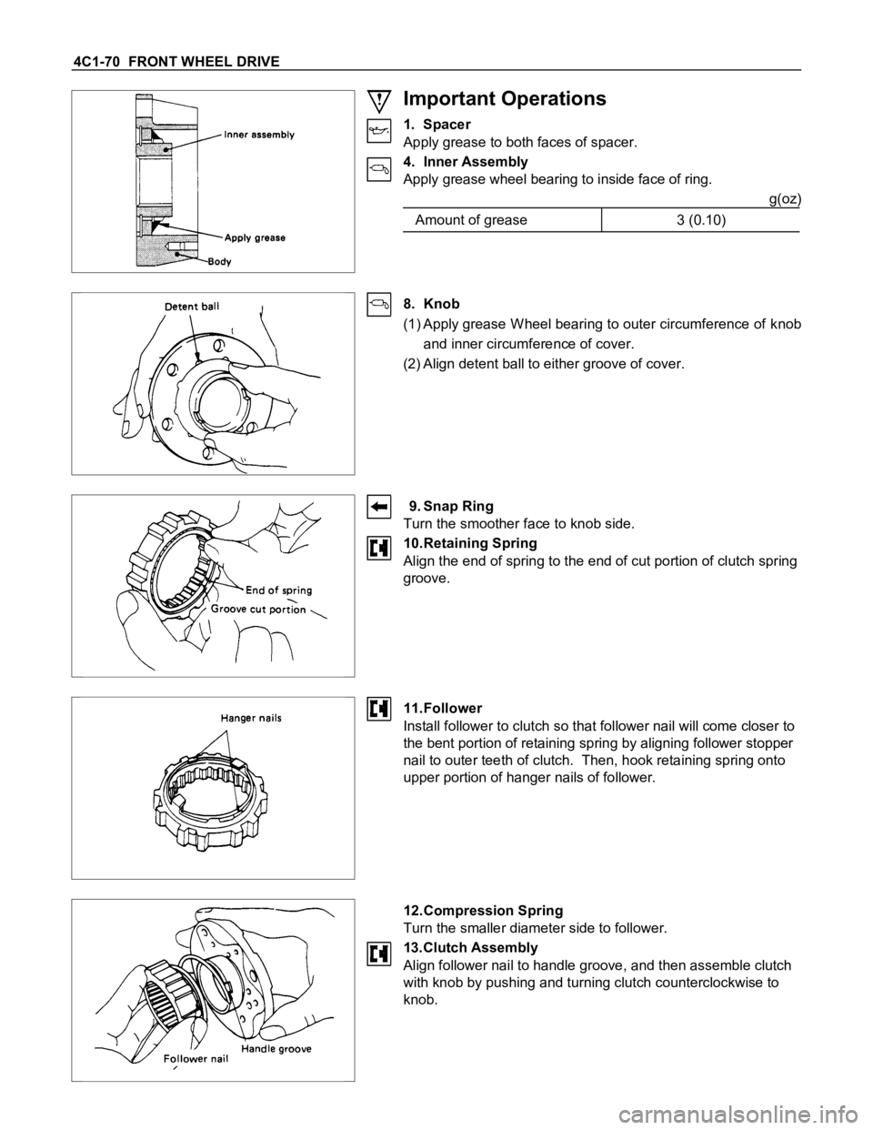
Important Operations
1. Spacer
Apply grease to both faces of spacer.
4. Inner Assembly
Apply grease wheel bearing to inside face of ring.
g(oz)
Amount of grease 3 (0.10)
8. Knob
(1) Apply grease W heel bearing to outer circumference of knob
and inner circumference of cover.
(2) Align detent ball to either groove of cover.
9. Snap Ring
Turn the smoother face to knob side.
10.Retaining Spring
Align the end of spring to the end of cut portion of clutch spring
groove.
11.Follower
Install follower to clutch so that follower nail will come closer to
the bent portion of retaining spring by aligning follower stopper
nail to outer teeth of clutch. Then, hook retaining spring onto
upper portion of hanger nails of follower.
12.Compression Spring
Turn the smaller diameter side to follower.
13.Clutch Assembly
Align follower nail to handle groove, and then assemble clutch
with knob by pushing and turning clutch counterclockwise to
knob.
Page 344 of 1600

5-16 BRAKES
From
primary
master cylinder From
Secondary
master cylinder
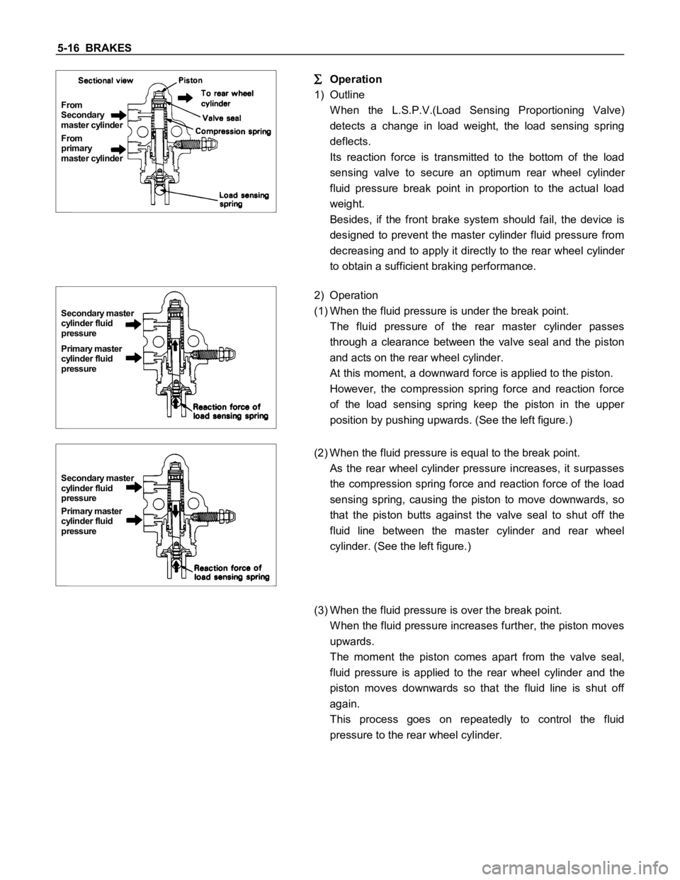
Operation
1) Outline
W hen the L.S.P.V.(Load Sensing Proportioning Valve)
detects a change in load weight, the load sensing spring
deflects.
Its reaction force is transmitted to the bottom of the load
sensing valve to secure an optimum rear wheel cylinder
fluid pressure break point in proportion to the actual load
weight.
Besides, if the front brake system should fail, the device is
designed to prevent the master cylinder fluid pressure from
decreasing and to apply it directly to the rear wheel cylinder
to obtain a sufficient braking performance.
Primary master
cylinder fluid
pressure Secondary master
cylinder fluid
pressure
2) Operation
(1) When the fluid pressure is under the break point.
The fluid pressure of the rear master cylinder passes
through a clearance between the valve seal and the piston
and acts on the rear wheel cylinder.
At this moment, a downward force is applied to the piston.
However, the compression spring force and reaction force
of the load sensing spring keep the piston in the upper
position by pushing upwards. (See the left figure.)
Primary master
cylinder fluid
pressure Secondary master
cylinder fluid
pressure
(2) When the fluid pressure is equal to the break point.
As the rear wheel cylinder pressure increases, it surpasses
the compression spring force and reaction force of the load
sensing spring, causing the piston to move downwards, so
that the piston butts against the valve seal to shut off the
fluid line between the master cylinder and rear wheel
cylinder. (See the left figure.)
(3) When the fluid pressure is over the break point.
W hen the fluid pressure increases further, the piston moves
upwards.
The moment the piston comes apart from the valve seal,
fluid pressure is applied to the rear wheel cylinder and the
piston moves downwards so that the fluid line is shut off
again.
This process goes on repeatedly to control the fluid
pressure to the rear wheel cylinder.