ISUZU TFS SERIES 1997 Workshop Manual
Manufacturer: ISUZU, Model Year: 1997, Model line: TFS SERIES, Model: ISUZU TFS SERIES 1997Pages: 1600, PDF Size: 40.98 MB
Page 1 of 1600
REAR AXLE 4B-5
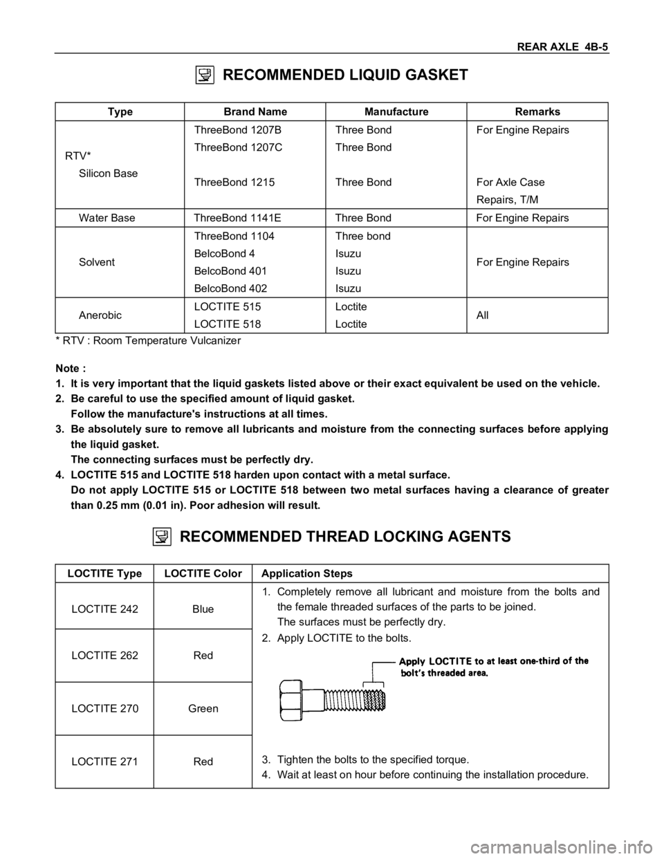
RECOMMENDED LIQUID GASKET
Type Brand Name Manufacture Remarks
RTV*
Silicon BaseThreeBond 1207B
ThreeBond 1207C
ThreeBond 1215Three Bond
Three Bond
Three BondFor Engine Repairs
For Axle Case
Repairs, T/M
Water Base ThreeBond 1141E Three Bond For Engine Repairs
SolventThreeBond 1104
BelcoBond 4
BelcoBond 401
BelcoBond 402Three bond
Isuzu
Isuzu
IsuzuFor Engine Repairs
AnerobicLOCTITE 515
LOCTITE 518Loctite
LoctiteAll
* RTV : Room Temperature Vulcanizer
Note :
1. It is very important that the liquid gaskets listed above or their exact equivalent be used on the vehicle.
2. Be careful to use the specified amount of liquid gasket.
Follow the manufacture's instructions at all times.
3. Be absolutely sure to remove all lubricants and moisture from the connecting surfaces before applying
the liquid gasket.
The connecting surfaces must be perfectly dry.
4. LOCTITE 515 and LOCTITE 518 harden upon contact with a metal surface.
Do not apply LOCTITE 515 or LOCTITE 518 between two metal surfaces having a clearance of greater
than 0.25 mm (0.01 in). Poor adhesion will result.
RECOMMENDED THREAD LOCKING AGENTS
LOCTITE Type LOCTITE Color Application Steps
LOCTITE 242 Blue1. Completely remove all lubricant and moisture from the bolts and
the female threaded surfaces of the parts to be joined.
The surfaces must be perfectly dry.
LOCTITE 262 Red2. Apply LOCTITE to the bolts.
LOCTITE 270 Green
LOCTITE 271 Red3. Tighten the bolts to the specified torque.
4. Wait at least on hour before continuing the installation procedure.
Page 2 of 1600
4B-6 REAR AXLE
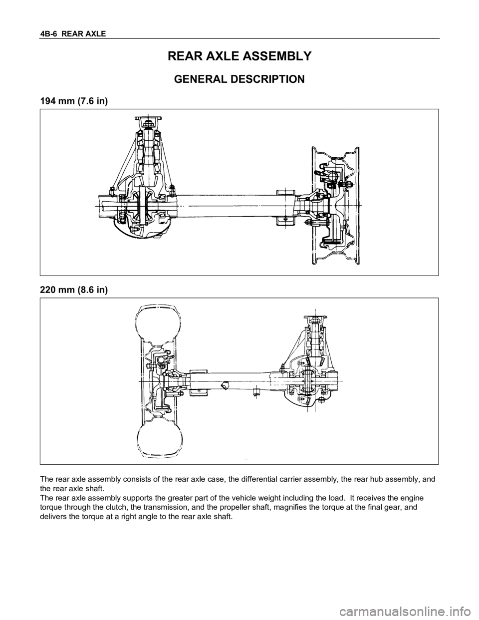
REAR AXLE ASSEMBLY
GENERAL DESCRIPTION
194 mm (7.6 in)
220 mm (8.6 in)
The rear axle assembly consists of the rear axle case, the differential carrier assembly, the rear hub assembly, and
the rear axle shaft.
The rear axle assembly supports the greater part of the vehicle weight including the load. It receives the engine
torque through the clutch, the transmission, and the propeller shaft, magnifies the torque at the final gear, and
delivers the torque at a right angle to the rear axle shaft.
Page 3 of 1600
REAR AXLE 4B-7
SERVICING
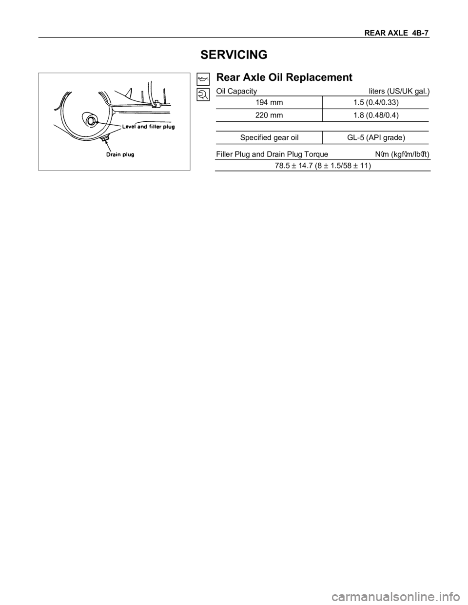
Rear Axle Oil Replacement
Oil Capacity liters (US/UK gal.)
194 mm 1.5 (0.4/0.33)
220 mm 1.8 (0.48/0.4)
Specified gear oil GL-5 (API grade)
Filler Plug and Drain Plug Torque Nm (kgfm/lbft)
78.5
14.7 (8 1.5/58 11)
Page 4 of 1600
4B-8 REAR AXLE
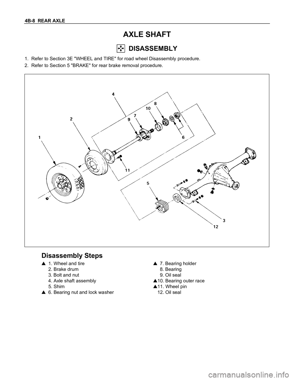
AXLE SHAFT
DISASSEMBLY
1. Refer to Section 3E "WHEEL and TIRE" for road wheel Disassembly procedure.
2. Refer to Section 5 "BRAKE" for rear brake removal procedure.
Disassembly Steps
1. Wheel and tire
2. Brake drum
3. Bolt and nut
4. Axle shaft assembly
5. Shim
6. Bearing nut and lock washer
7. Bearing holder
8. Bearing
9. Oil seal
10. Bearing outer race
11. Wheel pin
12. Oil seal
Page 5 of 1600
REAR AXLE 4B-9
Important Operations
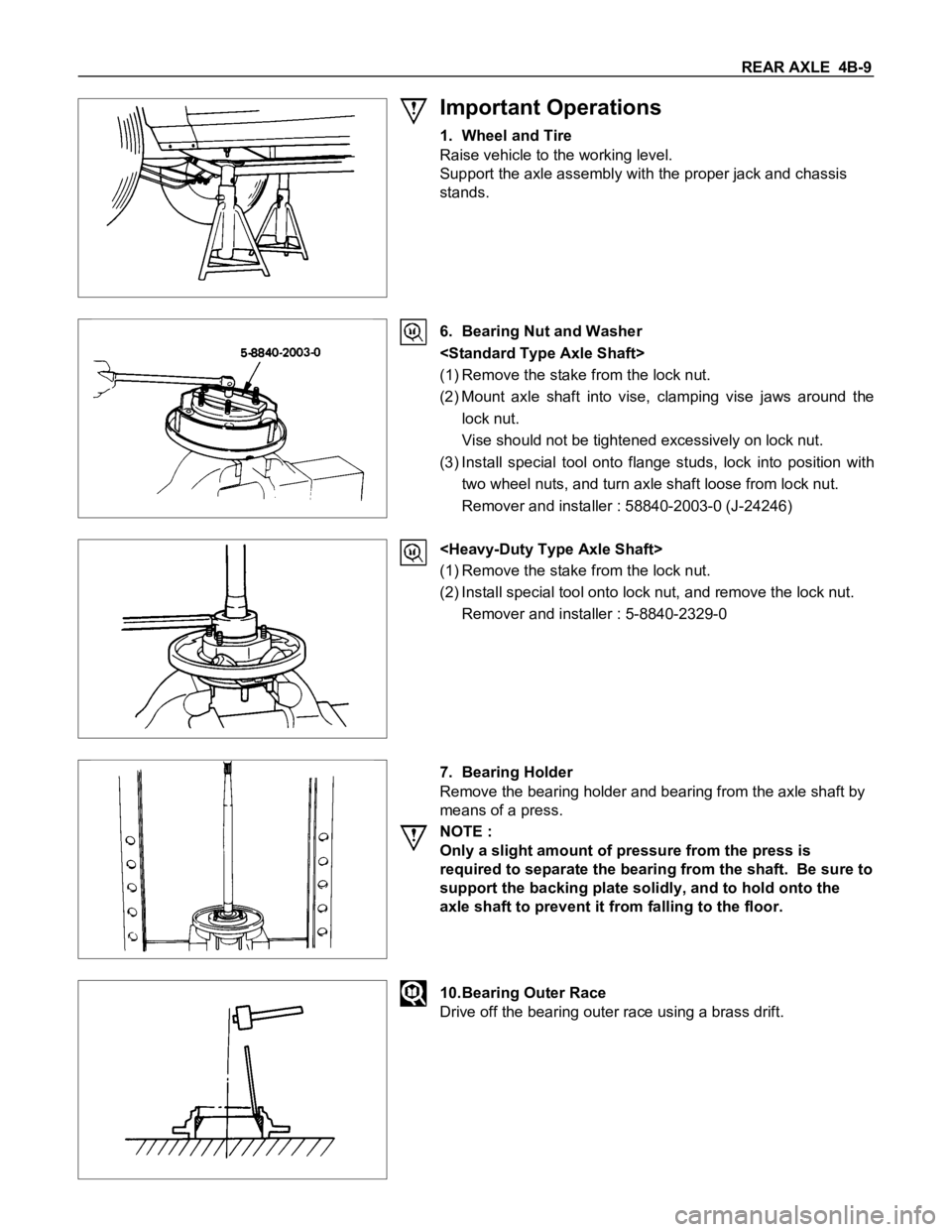
1. Wheel and Tire
Raise vehicle to the working level.
Support the axle assembly with the proper jack and chassis
stands.
6. Bearing Nut and Washer
(1) Remove the stake from the lock nut.
(2) Mount axle shaft into vise, clamping vise jaws around the
lock nut.
Vise should not be tightened excessively on lock nut.
(3) Install special tool onto flange studs, lock into position with
two wheel nuts, and turn axle shaft loose from lock nut.
Remover and installer : 58840-2003-0 (J-24246)
(1) Remove the stake from the lock nut.
(2) Install special tool onto lock nut, and remove the lock nut.
Remover and installer : 5-8840-2329-0
7. Bearing Holder
Remove the bearing holder and bearing from the axle shaft by
means of a press.
NOTE :
Only a slight amount of pressure from the press is
required to separate the bearing from the shaft. Be sure to
support the backing plate solidly, and to hold onto the
axle shaft to prevent it from falling to the floor.
10.Bearing Outer Race
Drive off the bearing outer race using a brass drift.
Page 6 of 1600
4B-10 REAR AXLE
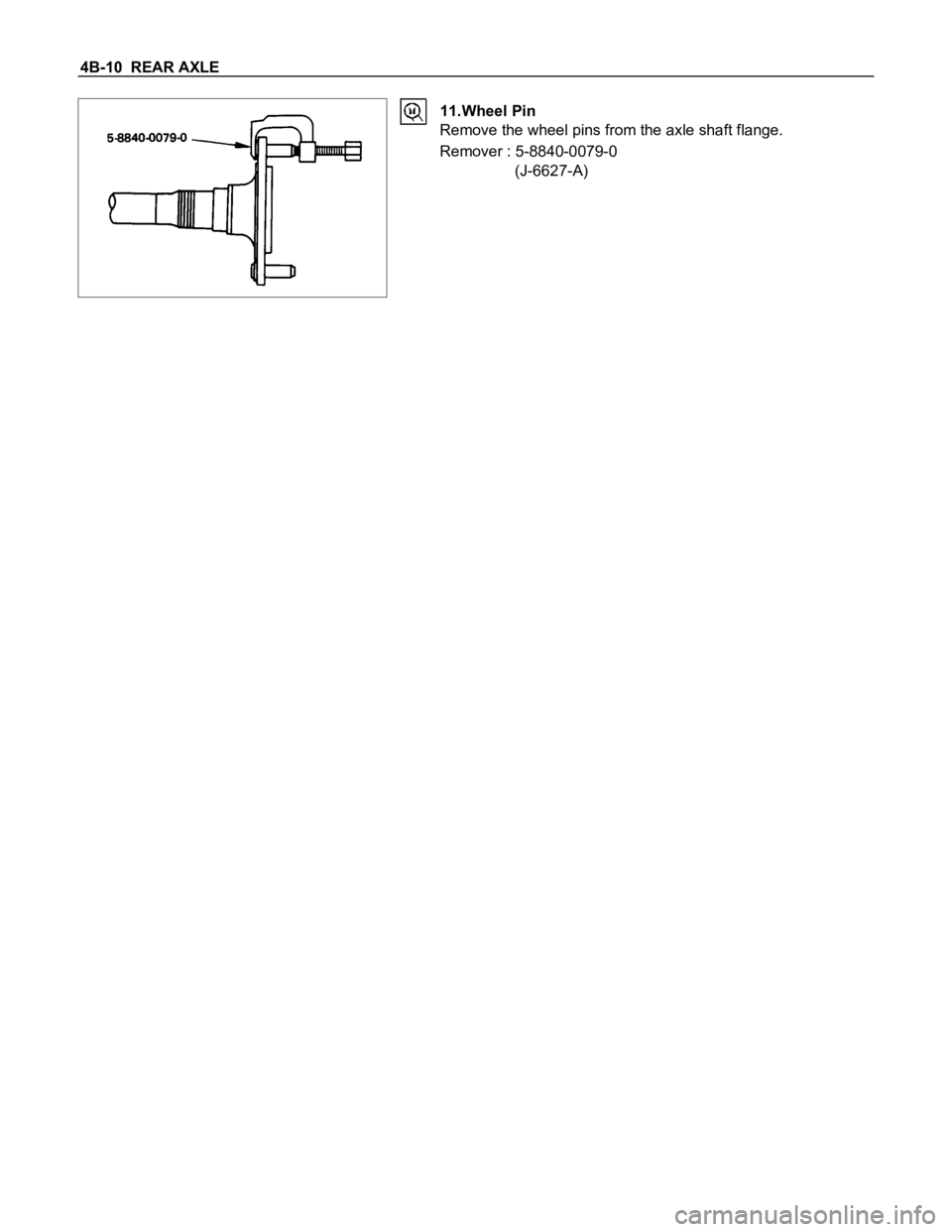
11.Wheel Pin
Remove the wheel pins from the axle shaft flange.
Remover : 5-8840-0079-0
(J-6627-A)
Page 7 of 1600
REAR AXLE 4B-11
INSPECTION AND REPAIR
Make all necessary adjustments, repairs, and part replacements if wear, damage, or other problems are discovered
during inspections.
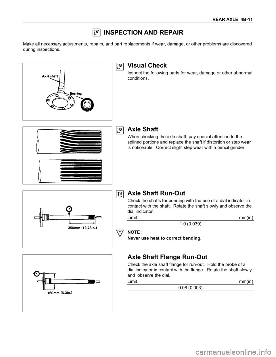
Visual Check
Inspect the following parts for wear, damage or other abnormal
conditions.
Axle Shaft
When checking the axle shaft, pay special attention to the
splined portions and replace the shaft if distortion or step wear
is noticeable. Correct slight step wear with a pencil grinder.
Axle Shaft Run-Out
Check the shafts for bending with the use of a dial indicator in
contact with the shaft. Rotate the shaft slowly and observe the
dial indicator.
Limit mm(in)
1.0 (0.039)
NOTE :
Never use heat to correct bending.
Axle Shaft Flange Run-Out
Check the axle shaft flange for run-out. Hold the probe of a
dial indicator in contact with the flange. Rotate the shaft slowly
and observe the dial.
Limit mm(in)
0.08 (0.003)
Page 8 of 1600
4B-12 REAR AXLE
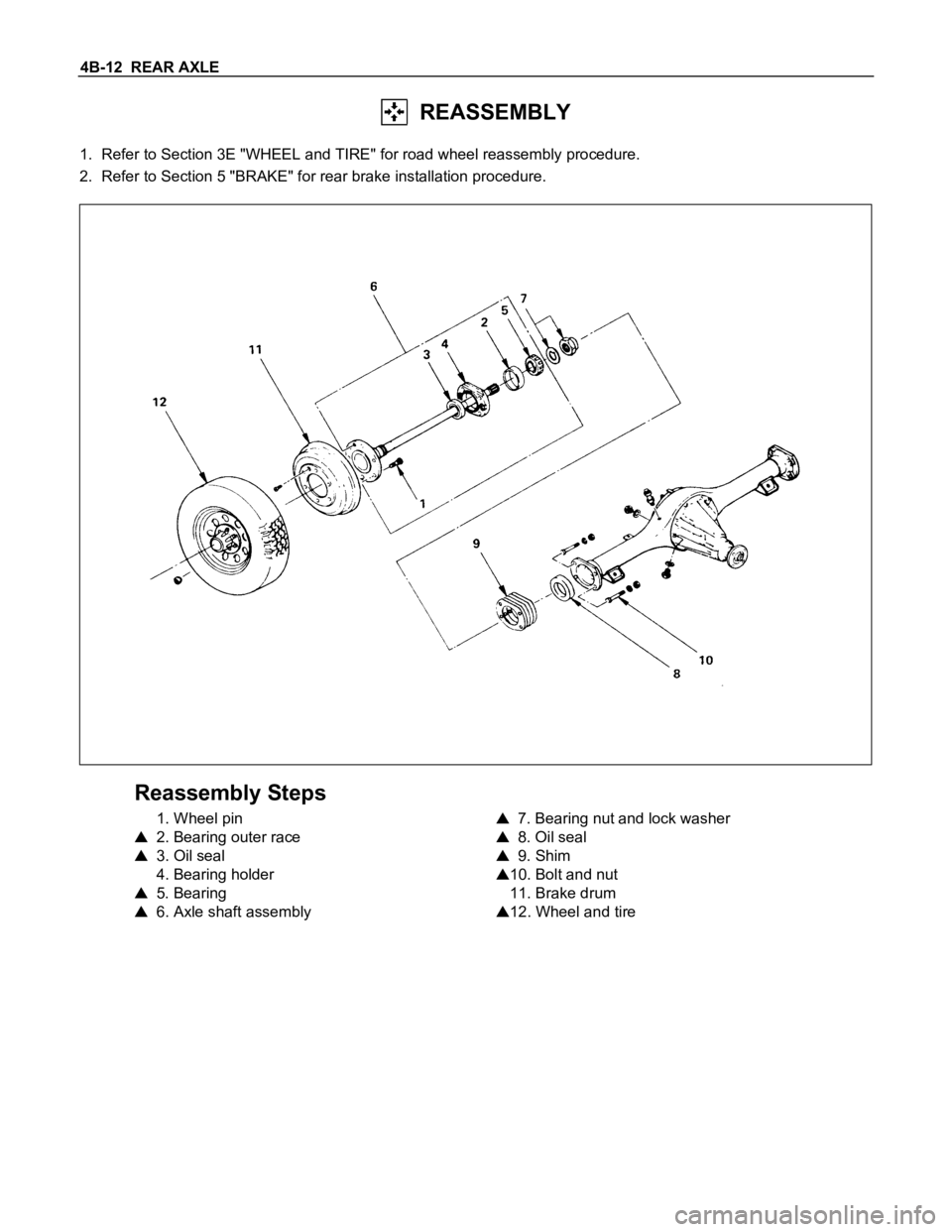
REASSEMBLY
1. Refer to Section 3E "WHEEL and TIRE" for road wheel reassembly procedure.
2. Refer to Section 5 "BRAKE" for rear brake installation procedure.
Reassembly Steps
1. Wheel pin
2. Bearing outer race
3. Oil seal
4. Bearing holder
5. Bearing
6. Axle shaft assembly
7. Bearing nut and lock washer
8. Oil seal
9. Shim
10. Bolt and nut
11. Brake drum
12. Wheel and tire
Page 9 of 1600
REAR AXLE 4B-13
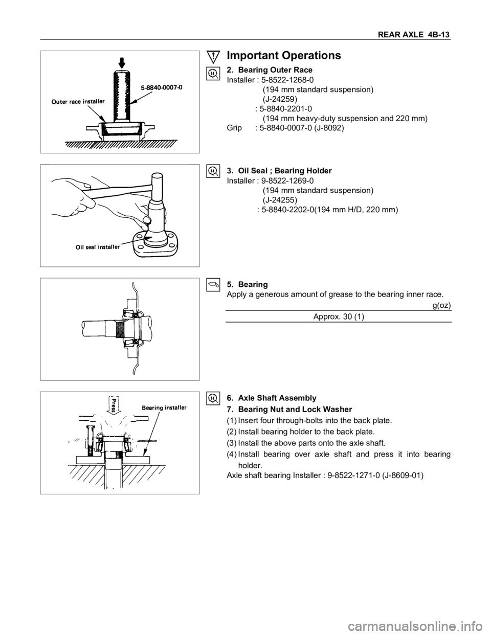
Important Operations
2. Bearing Outer Race
Installer : 5-8522-1268-0
(194 mm standard suspension)
(J-24259)
: 5-8840-2201-0
(194 mm heavy-duty suspension and 220 mm)
Grip : 5-8840-0007-0 (J-8092)
3. Oil Seal ; Bearing Holder
Installer : 9-8522-1269-0
(194 mm standard suspension)
(J-24255)
: 5-8840-2202-0(194 mm H/D, 220 mm)
5. Bearing
Apply a generous amount of grease to the bearing inner race.
g(oz)
Approx. 30 (1)
6. Axle Shaft Assembly
7. Bearing Nut and Lock Washer
(1) Insert four through-bolts into the back plate.
(2) Install bearing holder to the back plate.
(3) Install the above parts onto the axle shaft.
(4) Install bearing over axle shaft and press it into bearing
holder.
Axle shaft bearing Installer : 9-8522-1271-0 (J-8609-01)
Page 10 of 1600
4B-14 REAR AXLE
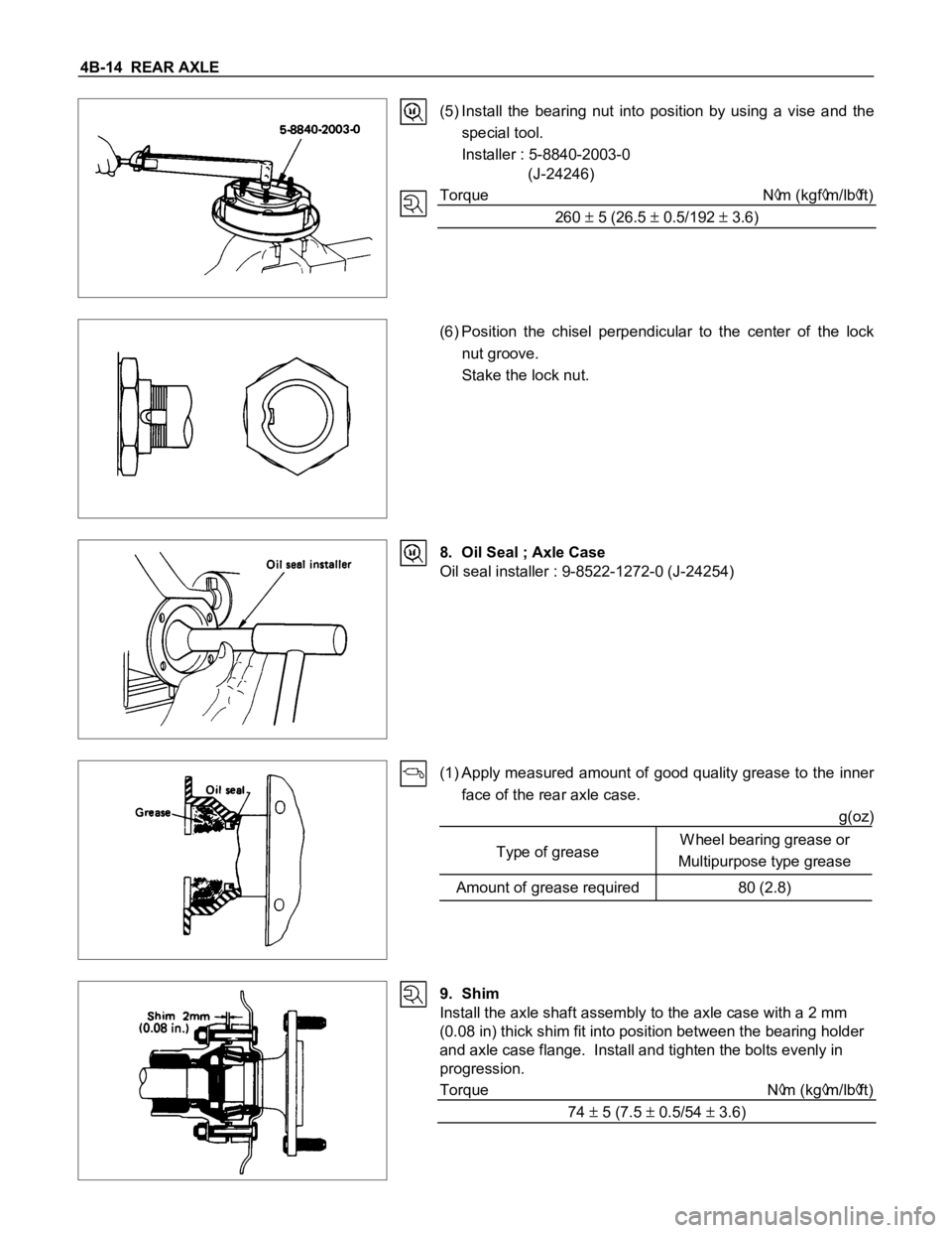
(5) Install the bearing nut into position by using a vise and the
special tool.
Installer : 5-8840-2003-0
(J-24246)
Torque N
m (kgfm/lbft)
260
5 (26.5 0.5/192 3.6)
(6) Position the chisel perpendicular to the center of the lock
nut groove.
Stake the lock nut.
8. Oil Seal ; Axle Case
Oil seal installer : 9-8522-1272-0 (J-24254)
(1) Apply measured amount of good quality grease to the inner
face of the rear axle case.
g(oz)
Type of greaseW heel bearing grease or
Multipurpose type grease
Amount of grease required 80 (2.8)
9. Shim
Install the axle shaft assembly to the axle case with a 2 mm
(0.08 in) thick shim fit into position between the bearing holder
and axle case flange. Install and tighten the bolts evenly in
progression.
Torque N
m (kgm/lbft)
74
5 (7.5 0.5/54 3.6)