oil pressure ISUZU TFS SERIES 1997 Workshop Manual
[x] Cancel search | Manufacturer: ISUZU, Model Year: 1997, Model line: TFS SERIES, Model: ISUZU TFS SERIES 1997Pages: 1600, PDF Size: 40.98 MB
Page 99 of 1600

4C1-36 FRONT WHEEL DRIVE
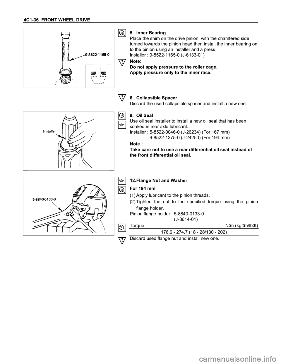
5. Inner Bearing
Place the shim on the drive pinion, with the chamfered side
turned towards the pinion head then install the inner bearing on
to the pinion using an installer and a press.
Installer : 9-8522-1165-0 (J-6133-01)
Note:
Do not apply pressure to the roller cage.
Apply pressure only to the inner race.
6. Collapsible Spacer
Discard the used collapsible spacer and install a new one.
9. Oil Seal
Use oil seal installer to install a new oil seal that has been
soaked in rear axle lubricant.
Installer : 5-8522-0046-0 (J-26234) (For 167 mm)
9-8522-1275-0 (J-24250) (For 194 mm)
Note :
Take care not to use a rear differential oil seal instead of
the front differential oil seal.
12.Flange Nut and Washer
For 194 mm
(1) Apply lubricant to the pinion threads.
(2) Tighten the nut to the specified torque using the pinion
flange holder.
Pinion flange holder : 5-8840-0133-0
(J-8614-01)
Torque N
m (kgfm/lbft)
176.6 - 274.7 (18 - 28/130 - 202)
Discard used flange nut and install new one.
Page 350 of 1600

5-22 BRAKES
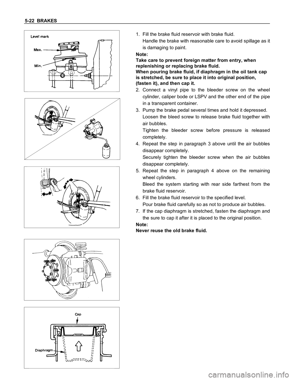
1. Fill the brake fluid reservoir with brake fluid.
Handle the brake with reasonable care to avoid spillage as it
is damaging to paint.
Note:
Take care to prevent foreign matter from entry, when
replenishing or replacing brake fluid.
When pouring brake fluid, if diaphragm in the oil tank cap
is stretched, be sure to place it into original position,
(fasten it), and then cap it.
2. Connect a vinyl pipe to the bleeder screw on the wheel
cylinder, caliper bode or LSPV and the other end of the pipe
in a transparent container.
3. Pump the brake pedal several times and hold it depressed.
Loosen the bleed screw to release brake fluid together with
air bubbles.
Tighten the bleeder screw before pressure is released
completely.
4. Repeat the step in paragraph 3 above until the air bubbles
disappear completely.
Securely tighten the bleeder screw when the air bubbles
disappear completely.
5. Repeat the step in paragraph 4 above on the remaining
wheel cylinders.
Bleed the system starting with rear side farthest from the
brake fluid reservoir.
6. Fill the brake fluid reservoir to the specified level.
Pour brake fluid carefully so as not to produce air bubbles.
7. If the cap diaphragm is stretched, fasten the diaphragm and
the sure to cap it after it is placed to the original position.
Note:
Never reuse the old brake fluid.
Page 395 of 1600

BRAKES 5-67
TROUBLESHOOTING
Condition and Cause Correction
Poor Brake Action
Master cylinder faulty Correct or replace
Power cylinder faulty Correct or replace
Level of brake fluid in reservoir too low Replenish and bleed
Air in hydraulic circuit Bleed
Front disc brake caliper faulty Clean or replace
Rear brake wheel cylinder faulty Clean or replace
Water or oil on brake pads or linings Clean or replace
Brake pads or linings hardened Replace
Brake pads or linings in poor contact with rotor or brake drum Correct
Brake pads or linings worn Replace
Brake disc or drum rusted Grind or replace
Check valve in vacuum hose faulty Correct or replace
Brake Squeak
Brake pads or linings worn Replace
Brake pads or linings hardened Replace
Brake pads or linings in poor contact with rotor or brake drum Correct
Brake disc(s) warped, worn or damaged Grind or replace
Disc brake anti-squeak shims fatigued Replace
Front hub bearings loose or preload is incorrect Adjust or replace
Brake disc or drum rusted Grind or replace
Brake Pull
Tire inflation pressures unequal Adjust
Front wheel alignment incorrect Adjust
Water or oil on brake pads or linings Clean or replace
Brake pads or linings hardened Replace
Brake pads or linings worn excessively Replace
Brake drum or rotor worn or scored Grind or replace
Front or rear wheel cylinder or disc brake caliper malfunctioning Clean or replace
Front hub bearing preload incorrect Adjust or replace
Brake pad or lining clearances unequal Adjust or replace
Brake Drag
Parking brake maladjusted Adjust
Brake pad or lining clearance insufficient Adjust
Brake pedal free play insufficient Adjust brake pedal height or power cylinder operating rod
Piston in master cylinder sticking Clean or replace
Pistons in disc brake caliper sticking Replace piston seals
Pistons in rear brake wheel cylinders sticking Clean or replace
Brake pads sticking in caliper Clean
Return springs weakened Replace
Parking brake binding Overhaul rear brakes
Front hub bearing preload incorrect Adjust or replace
Rear brake shoes not returning Correct or replace brake back plate, check automatic adjuster and
replace as necessary
Obstructions in hydraulic circuit Clean
Rotor warped excessively Grind or replace
Rear brake drum distorted Grind or replace
Piston cups swollen Replace brake fluid and piston cups
Check valve ; vacuum hose faulty Replace
Parking cable sticking Clean or replace
Rear disc brake over adjust Adjust or overhaul rear brakes
Excessive Brake Pedal Travel
Air in hydraulic circuit Bleed hydraulic circuit
Level of brake fluid in reservoir too low Replenish brake fluid reservoir to specified level and bleed hydraulic
circuit as necessary.
Master cylinder push rod clearance excessive Adjust
Leakage in hydraulic system Correct or replace defective parts
Rear disc brake autoadjuster malfunction Overhaul rear brakes
Page 583 of 1600

CLUTCH 7C-43
Checkpoint Trouble Cause Countermeasure
Replace the release bearingRelease bearing broken
Clean the related parts and/or
replace the facing
Replace the crankshaft rear oil
seal
Defective crankshaft rear oil
seal
NG NG
OK OKGrease or oil adhering to the
facing
Clutch diaphragm springReplace the clutch pressure
plate assemblyW eak or broken clutch
diaphragm spring
Replace the driven plate
assemblyWorn facing
NG NG
OKFacing Continued from the previous page
Page 586 of 1600

7C-46 CLUTCH
3. CLUTCH SHUDDER
Checkpoint Trouble Cause Countermeasure
Grease or oil adhering to the
facing
Clean the related parts and/or
replace the facing
Replace the transmission front
cover oil seal
Replace the pressure plate
assembly
Defective transmission front
cover oil seal
Pressure plate unevenly wornPressure plate
Clean the related parts and/or
replace the facing
Tighten the connections
Repair or replace the
applicable parts
Too much grease
Poorly connected components
causing looseness and
abrasion
OK
NG NG NG NG
OK
Power train
Clean and grease the spline
contact surface
Insufficient grease on the
spline contact surface of the
splined hub
Driven plate
Clean or repair the top gear
shaft spline
Replace the top gear shaft
Clean the related parts and/or
replace the facing
Replace the crankshaft rear oil
seal
Corrosion or step wear on the
top gear shaft spline
Defective crankshaft rear oil
seal
OKNG NG NG
OK
Continued on the next page