parking brake ISUZU TFS SERIES 1997 Workshop Manual
[x] Cancel search | Manufacturer: ISUZU, Model Year: 1997, Model line: TFS SERIES, Model: ISUZU TFS SERIES 1997Pages: 1600, PDF Size: 40.98 MB
Page 11 of 1600

REAR AXLE 4B-15
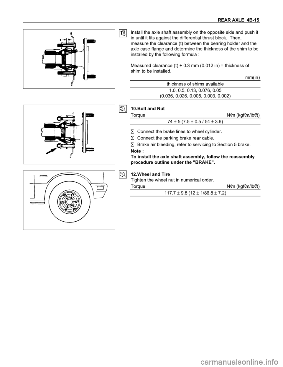
Install the axle shaft assembly on the opposite side and push it
in until it fits against the differential thrust block. Then,
measure the clearance (t) between the bearing holder and the
axle case flange and determine the thickness of the shim to be
installed by the following formula :
Measured clearance (t) + 0.3 mm (0.012 in) = thickness of
shim to be installed.
mm(in)
thickness of shims available
1.0, 0.5, 0.13, 0.076, 0.05
(0.036, 0.026, 0.005, 0.003, 0.002)
10.Bolt and Nut
Torque N
m (kgfm/lbft)
74
5 (7.5 0.5 / 54 3.6)
Connect the brake lines to wheel cylinder.
Connect the parking brake rear cable.
Brake air bleeding, refer to servicing to Section 5 brake.
Note :
To install the axle shaft assembly, follow the reassembly
procedure outline under the "BRAKE".
12.Wheel and Tire
Tighten the wheel nut in numerical order.
Torque N
m (kgfm/lbft)
117.7
9.8 (12 1/86.8 7.2)
Page 329 of 1600

BRAKES 5-1
SECTION 5
BRAKES
TABLE OF CONTENTS
PAGE
General Description......................................................................................................... 5-3
Main Data and Specifications ...................................<0011001100110011001100110011001100110011001100110011001100110011001100110011001100110011001100110011001100110011001100110011001100110011001100110011001100110011001100110011001100110011001100110011001100
11001100110011[ 5- 8
Special Parts Fixing Nut and Bolt.................................................................................. 5- 9
Servicing<0011001100110011001100110011001100110011001100110011001100110011001100110011001100110011001100110011001100110011001100110011001100110011001100110011001100110011001100110011001100110011001100110011001100
11001100110011[<0011001100110011001100110011001100110011001100110011001100110011001100110011001100110011001100110011001100110011001100110011001100110011001100110011001100110011001100110011001100110011001100110011001100
11001100110011001100110011001100110011001100110011[...... 5-15
Front Brake Assembly ..................................................................................................... 5-28
Removal and Installation............................................................................................ 5-28
Removal and installation of Disc Pad ....................................................................... 5-31
Disassembly <0011001100110011001100110011001100110011001100110011001100110011001100110011001100110011001100110011001100110011001100110011001100110011001100110011001100110011001100110011001100110011001100110011001100
110011[<0011001100110011001100110011001100110011001100110011001100110011001100110011001100110011001100110011001100110011001100110011001100110011001100110011001100110011001100110011001100110011001100110011001100
11001100110011001100110011001100110011[ 5-33
Inspection and Repair................................................................................................. 5-35
Reassembly <0011001100110011001100110011001100110011001100110011001100110011001100110011001100110011001100110011001100110011001100110011001100110011001100110011001100110011001100110011001100110011001100110011001100
1100110011[<0011001100110011001100110011001100110011001100110011001100110011001100110011001100110011001100110011001100110011001100110011001100110011001100110011001100110011001100110011001100110011001100110011001100
11001100110011001100110011001100110011[ 5-37
Rear Drum Brake Assembly............................................................................................ 5-39
Disassembly <0011001100110011001100110011001100110011001100110011001100110011001100110011001100110011001100110011001100110011001100110011001100110011001100110011001100110011001100110011001100110011001100110011001100
110011[<0011001100110011001100110011001100110011001100110011001100110011001100110011001100110011001100110011001100110011001100110011001100110011001100110011001100110011001100110011001100110011001100110011001100
11001100110011001100110011001100110011[ 5-39
Inspection and Repair................................................................................................. 5-40
Reassembly <0011001100110011001100110011001100110011001100110011001100110011001100110011001100110011001100110011001100110011001100110011001100110011001100110011001100110011001100110011001100110011001100110011001100
1100110011[<0011001100110011001100110011001100110011001100110011001100110011001100110011001100110011001100110011001100110011001100110011001100110011001100110011001100110011001100110011001100110011001100110011001100
11001100110011001100110011001100110011[ 5-42
Brake Control ................................................................................................................... 5-45
Removal and Installation .......................................<0011001100110011001100110011001100110011001100110011001100110011001100110011001100110011001100110011001100110011001100110011001100110011001100110011001100110011001100110011001100110011001100110011001100
1100110011[ 5-45
Master Cylinder ................................................................................................................5-46
Removal and Installation .......................................<0011001100110011001100110011001100110011001100110011001100110011001100110011001100110011001100110011001100110011001100110011001100110011001100110011001100110011001100110011001100110011001100110011001100
1100110011[ 5-46
Disassembly <0011001100110011001100110011001100110011001100110011001100110011001100110011001100110011001100110011001100110011001100110011001100110011001100110011001100110011001100110011001100110011001100110011001100
110011[<0011001100110011001100110011001100110011001100110011001100110011001100110011001100110011001100110011001100110011001100110011001100110011001100110011001100110011001100110011001100110011001100110011001100
11001100110011001100110011001100110011[ 5-47
Inspection and Repair................................................................................................. 5-49
Reassembly <0011001100110011001100110011001100110011001100110011001100110011001100110011001100110011001100110011001100110011001100110011001100110011001100110011001100110011001100110011001100110011001100110011001100
1100110011[<0011001100110011001100110011001100110011001100110011001100110011001100110011001100110011001100110011001100110011001100110011001100110011001100110011001100110011001100110011001100110011001100110011001100
11001100110011001100110011001100110011[ 5-51
Vacuum Servo ..................................................................................................................5-53
Removal and Installation .......................................<0011001100110011001100110011001100110011001100110011001100110011001100110011001100110011001100110011001100110011001100110011001100110011001100110011001100110011001100110011001100110011001100110011001100
1100110011[ 5-53
Parking Brake (Stem Type) ............................................................................................. 5-56
Removal and installation .......................................<0011001100110011001100110011001100110011001100110011001100110011001100110011001100110011001100110011001100110011001100110011001100110011001100110011001100110011001100110011001100110011001100110011001100
1100110011[ 5-56
Disassembly and Reassembly ................................................................................... 5-61
Inspection and Repair................................................................................................. 5-63
Parking Brake (Floor Mount Type) ................................................................................. 5-64
INDEX
Page 340 of 1600

5-12 BRAKES
BRAKE PEDAL ASSEMBLYNm(kgfm/lbft)
This illustration is besed on the LHD model 11-20 (1.1-2.0/8-1429-39 (3.0-4.0/22-29)
PARKING BRAKE STEM ASSEMBLY
(STEM TYPE, LEFT HAND DRIVE MODEL)
Nm(kgfm/lbft)
21-34 (2.1-3.5/15-25) 11-20 (1.1-2.0/8-14)14-25 (1.4-2.5/10-18)
Page 341 of 1600

BRAKES 5-13
PARKING BRAKE STEM ASSEMBLY
(STEM TYPE, RIGHT HAND DRIVE MODEL)
Nm(kgfm/lbft)
18-24 (1.8-2.4/13-17)11-20 (1.1-2.0/8-14) 14-25 (1.4-2.5/10-18)
BRAKE LINES (HOSES AND PIPES)
(MODEL WITH BLEND PROPORTIONING VALVE)
Nm(kgfm/lbft)
29-39
(3.0-4.0/22-29)13-19 (1.3-1.9/9.4-14)11-20 (1.1-2.2/8-14)
7.8-18 (0.8-1.8/5.8-13)13-19 (1.3-1.9/9.4-14)
Page 342 of 1600

5-14 BRAKES
BRAKE LINES (HOSES AND PIPES) (MODEL WITH LSPV)Nm(kgfm/lbft)
29-39 (3.0-4.0/22-29)13-19 (1.3-1.9/9.4-14)11-20 (1.1-2.0/8-14) 13-19 (1.3-1.9/9.4-14)7.8-18 (0.8-1.8/5.8-13)13-19 (1.3-1.9/9.4-14)
PARKING BRAKE LEVER ASSEMBLY (FLOOR MOUNT TYPE)Nm(kgfm/lbft)
Page 349 of 1600

BRAKES 5-21
Operation
The operation of the P-valve by the master cylinder
pressure is unchanged up to the brake points
A and B.
If master cylinder fluid pressure penetrates into the second
break point
B, the fluid pressure pressing against the seal
2, (which isolated route 4 and route 5), passing the route
4 of the master cylinder side, overcomes the operating
force of the spring
3 + fluid pressure affecting the seal 2 of
the wheel cylinder, and presses the piston
1 to the right
side, resulting in the opening of the routes
4 and 5, and
canceling of the P-valve operation.
Then, because the master cylinder fluid pressure and the
wheel cylinder fluid pressure, up to the point
C, operate on
the identical surface of the seal
2, both have identical
ascending ratio.
However, because of the operation of spring
3 in the wheel
cylinder side, wheel cylinder fluid pressure operate to
preserve the balance against the master cylinder fluid
pressure on the lower level with the difference in pressure
resulting from this spring.
Valve Maintenance
In the case of fluid leak or other abnormalities, faulty valve
should be replaced.
The valve is set up at the right hand side of the 5th
crossmember near the rear axle.
Note:
The blend proportioning valve is not repairable and must
be replaced as a complete assembly.
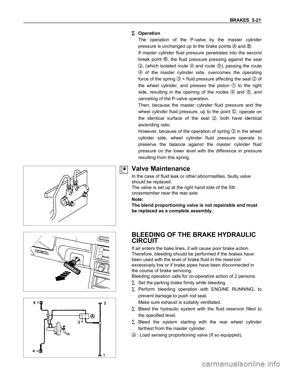
BLEEDING OF THE BRAKE HYDRAULIC
CIRCUIT
If air enters the bake lines, it will cause poor brake action.
Therefore, bleeding should be performed if the brakes have
been used with the level of brake fluid in the reservoir
excessively low or if brake pipes have been disconnected in
the course of brake servicing.
Bleeding operation calls for co-operative action of 2 persons.
Set the parking brake firmly while bleeding.
Perform bleeding operation with ENGINE RUNNING, to
prevent damage to push rod seal.
Make sure exhaust is suitably ventilated.
Bleed the hydraulic system with the fluid reservoir filled to
the specified level.
Bleed the system starting with the rear wheel cylinder
farthest from the master cylinder.
A : Load sensing proportioning valve (If so equipped).
Page 352 of 1600

5-24 BRAKES
ADJUSTMENT PROCEDURE OF SERVICE AND PARKING BRAKE
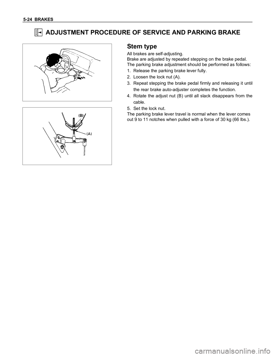
Stem type
All brakes are self-adjusting.
Brake are adjusted by repeated stepping on the brake pedal.
The parking brake adjustment should be performed as follows:
1. Release the parking brake lever fully.
2. Loosen the lock nut (A).
3. Repeat stepping the brake pedal firmly and releasing it until
the rear brake auto-adjuster completes the function.
4. Rotate the adjust nut (B) until all slack disappears from the
cable.
5. Set the lock nut.
The parking brake lever travel is normal when the lever comes
out 9 to 11 notches when pulled with a force of 30 kg (66 lbs.).
Page 353 of 1600

BRAKES 5-25
Floor mount type
All brakes are self-adjusting.
Brakes are adjusted by repeated stepping on the brake pedal.
(After stepping on the pedal and releasing it, the rear auto-
adjuster, in the rear brake, produces a clicking sound.
the same operation should be repeated until the sound
disappears.)
Take the following steps after overhauling the rear brake
assembly.
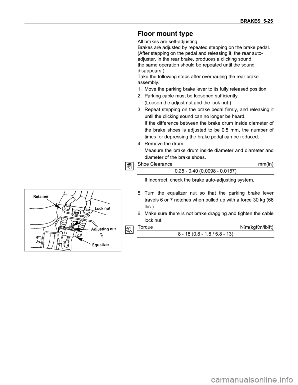
1. Move the parking brake lever to its fully released position.
2. Parking cable must be loosened sufficiently.
(Loosen the adjust nut and the lock nut.)
3. Repeat stepping on the brake pedal firmly, and releasing it
until the clicking sound can no longer be heard.
If the difference between the brake drum inside diameter of
the brake shoes is adjusted to be 0.5 mm, the number of
times for depressing the brake pedal can be reduced.
4. Remove the drum.
Measure the brake drum inside diameter and diameter and
diameter of the brake shoes.
Shoe Clearance mm(in)
0.25 - 0.40 (0.0098 - 0.0157)
If incorrect, check the brake auto-adjusting system.
5. Turn the equalizer nut so that the parking brake lever
travels 6 or 7 notches when pulled up with a force 30 kg (66
lbs.).
6. Make sure there is not brake dragging and tighten the cable
lock nut.
Torque N
m(kgfm/lbft)
8 - 18 (0.8 - 1.8 / 5.8 - 13)
Page 384 of 1600

5-56 BRAKES
PARKING BRAKE (STEM TYPE)
REMOVAL AND INSTALLATION
PARKING BRAKE STEM ASSEMBLY (LEFT HAND DRIVE MODEL)
Removal Steps
1. Cable front, relay lever side
2. Bolt ; bracket to dash
3. Bolt ; bracket to cross beam
4. Parking brake stem assembly
Installation Steps
To install, follow the removal procedure in
reverse order.
Page 385 of 1600

BRAKES 5-57
PARKING BRAKE STEM ASSEMBLY (RIGHT HAND DRIVE MODEL)
Removal Steps
1. Bolt and nut
2. Collar
3. Roller
4. Cable front, relay lever side
5. Nuts ; bracket to dash
6. Bolt ; bracket to cross beam
7. Parking brake stem assembly
8. Nuts
9. Bracket ; roller
Installation Steps
To install, follow the removal procedure in
reverse order.
Before installation, apply chassis grease to the
roller (3)'s contact surface to the collar (2) and
cable (4).