jack points ISUZU TROOPER 1995 Workshop Manual
[x] Cancel search | Manufacturer: ISUZU, Model Year: 1995, Model line: TROOPER, Model: ISUZU TROOPER 1995Pages: 1928
Page 5 of 1928
GENERAL INFORMATION OA-1
GENERAL INFORMATION
CONTENTS
General Information ........................................................ /.. . . . . . . . . Section OA / Maintenance and Lubrication ............................................. ~·. . . . . . . . . . . . . Section 08
SECTION OA
GENERAL INFORMATION
CONTENTS
General repair instructions ...................... OA-1 Standard bolts torque
specifications .......... OA-9
How to use this manual. ......................... OA-2 Abbreviations
charts ............................. OA-10
Identification
....................................... OA-5 Service
parts identification plate ............... OA-12
Lifting instructions ................................ OA-7
GENERAL REPAIR INSTRUCTIONS
1. If a floor jack is used, the following precautions
are recommended.
Park
vehicle on level ground, "block" front or
rear wheels, set jack against the recommended
lifting points (see "Lifting instructions" in this
section), raise
vehicle and support with chassis
stands and then perform service operations.
2. Before performing service operations, disconnect
ground
cable from the battery to reduce the
chance
of cable damage and burning due to
short circuiting.
3. Use a cover on body, seats and floor to protect
them against damage and contamination.
4. Brake fluid and anti-freeze solution must be
handled with reasonable care, as they can cause
paint damage.
5. The use of proper tools and recommended
essential and available tools, where specified, is
important for efficient and reliable performance
of service repairs.
6. Use genuine lsuzu parts.
7. Used cotter pins, plastic clips, gaskets, 0-rings,
oil seals, lock washers and self-locking nuts
should be discarded and new ones should be
installed, as normal function of the parts cannot
be maintained
if these parts are reused.
8. To facilitate proper and smooth reassembly
operation, keep disassembled parts neatly in
groups. Keeping fixing
bolts and nuts separate
is
very important, as they vary in hardness and
design depending on position
of installation.
9. Clean the parts before inspection or reassembly.
Also clean oil
ports, etc. using compressed air,
and make certain
they are free from restrictions.
10. Lubricate rotating and sliding faces of the parts
with oil or grease before installation.
11. When necessary, use a sealer on gaskets to pre
vent leakage.
12. Carefully observe all specifications for bolt and
nut torques.
13. When removing or replacing parts that require
refrigerant
to be discharged from the air
conditioning system, be sure
to use the Vehicle
Refrigerant Recovery and Recycling Equipment
(VRRRE) to recover and recycle Refrigerant-
134a.
14. When a service operation is completed, make a
final check to be sure the service has been done
properly and the problem has been corrected.
Page 11 of 1928
GENERAL INFORMATION OA-7
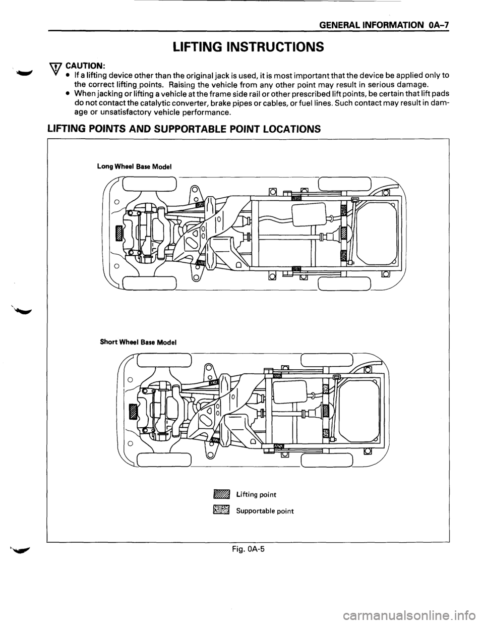
LIFTING INSTRUCTIONS
w CAUTION:
• • If a lifting device other than the original jack is used, it is most important that the device be applied only to
the correct lifting points. Raising the vehicle
from any other point may result in serious damage.
• When jacking or lifting a vehicle at the frame side rail or other prescribed lift points, be certain that lift pads
do not contact the catalytic converter, brake pipes or cables, or fuel lines. Such contact may result in dam
age
or unsatisfactory vehicle performance.
LIFTING POINTS AND SUPPORTABLE POINT LOCATIONS
Long Wheel Base Model
Short Wheel Base Model
-Lifting point
~ Supportable point
·~ Fig.OA-5
Page 119 of 1928
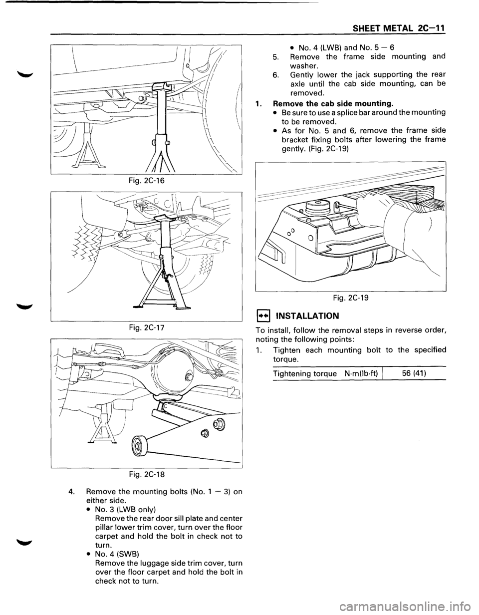
Fig. 2C-16
Fig. 2C-17
Fig. 2C-18
4. Remove the mounting bolts (No. 1 -3) on
either side.
• No. 3 (LWB only)
Remove the rear door sill plate and center
pillar lower trim cover, turn over the floor
carpet and hold the bolt in check not to
turn.
• No.4 (SWB)
Remove the
luggage side trim cover, turn
over the floor carpet and hold the bolt in
check
not to turn.
SHEET METAL 2C-11
• No. 4 (LWB) and No. 5-6
5. Remove the frame side mounting and
washer.
6. Gently lower the jack supporting the rear
axle until the cab side mounting, can be
removed.
1. Remove the cab side mounting.
• Be sure to use a splice bar around the mounting
to be removed.
• As for No. 5 and 6, remove the frame side
bracket fixing
bolts after lowering the frame
gently. (Fig. 2C-19)
Fig. 2C-19
1••1 INSTALLATION
To install, follow the removal steps in reverse order,
noting the
following points:
1. Tighten each mounting bolt to the specified
torque.
Tightening torque
N·m(lb·ft) I 56 (41)
Page 1035 of 1928
AUTOMATIC TRANSMISSION (4L30-E) 7A-163
I••IINSTALLALTION
To install, follow the removal steps in the reverse
order,
noting the following points;
22. Transmission assembly
•
Slowly raise transmission jack until front of
the transmission is aligned with rear of the
engine.
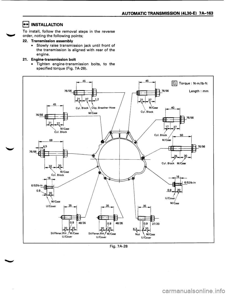
21. Engine-transmission
bolt
•
Tighten engine-transmission bolts, to the
specified
torque (Fig. 7A-28).
76/56
21 27 1.2
Cy~Bioc~21ip; Breather Hose
M/Case
68
Stiffener;R H M/Case U/Cover
Fig. 7A-28
45
35 ~ Torque : N·m/lb·ft
Length: mm
40
,---iEJE~I:=ll=1_::76/56
Cyl Blo~ r--1
M/Case J
1
-------e9E~~=~a.l_76/56
~ Cyl. Block M/Case
M/Case
Page 1097 of 1928
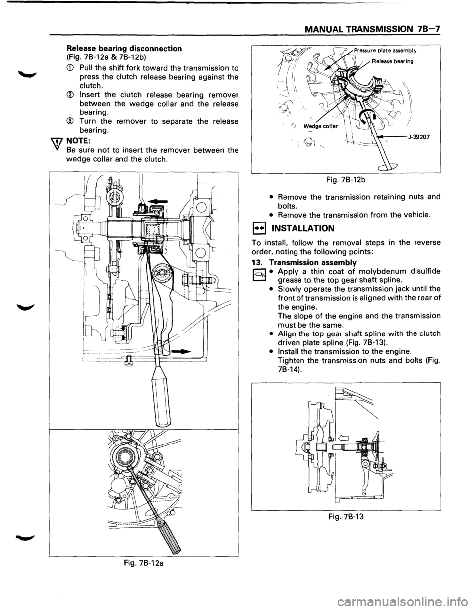
Release bearing disconnection
(Fig. 7B-12a & 7B-12b)
CD Pull the shift fork toward the transmission to
press the clutch release bearing against the
clutch.
® Insert the clutch release bearing remover
between the
wedge collar and the release
bearing.
® Turn the remover to separate the release
bearing.
IDNOTE:
Yl Be sure not to insert the remover between the
wedge collar and the clutch.
Fig. 7B-12a
MANUAL TRANSMISSION 78-7
Fig. 7B-12b
• Remove the transmission retaining nuts and
bolts.
•
Remove the transmission from the vehicle.
1••1 INSTALLATION
To install, follow the removal steps in the reverse
order, noting the
following points:
13. Transmission assembly
r;:::;J • Apply a thin coat of molybdenum disulfide
D grease to the top gear shaft spline.
• Slowly
operate the transmission jack until the
front
of transmission is aligned with the rear of
the engine.
The
slope of the engine and the transmission
must be the same.
• Align the top gear shaft spline with the clutch
driven plate spline (Fig. 78-13).
• Install the transmission to the engine.
Tighten the transmission nuts and
bolts (Fig.
78-14).
Fig. 78-13
Page 1162 of 1928
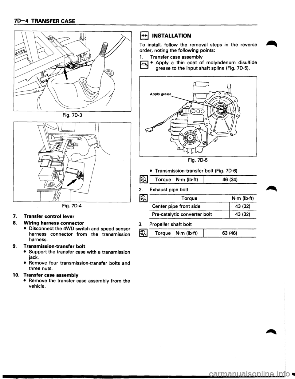
70-4 TRANSFER CASE
Fig. 70-3
Fig. 70-4
7. Transfer control lever
8. Wiring harness connector
• Disconnect the 4WD switch and speed sensor
harness connector from the transmission
harness.
9. Transmission-transfer bolt
• Support the transfer case with a transmission
jack.
• Remove four transmission-transfer bolts and
three nuts.
10. Transfer case assembly
• Remove the transfer case assembly from the
vehicle.
1••1 INSTALLATION
To install, follow the removal steps in the reverse ~
order, noting the following points:
1. Transfer case assembly
r;:;J • Apply a thin coat of molybdenum disulfide
D grease to the input shaft spline (Fig. 70-5).
Fig. 70-5
• Transmission-transfer bolt (Fig. 70-6)
1~1 Torque N·m (lb·ft)
2. Exhaust pipe bolt
1~1 Torque
Center pipe front side
Pre-catalytic converter bolt
3. Propeller shaft bolt
1~1 Torque N·m (lb·ft)
46 (34)
N·m (lb·ft)
43 (32)
43 (32)
63 (46)
•