ISUZU TROOPER 1995 Workshop Manual
Manufacturer: ISUZU, Model Year: 1995, Model line: TROOPER, Model: ISUZU TROOPER 1995Pages: 1928
Page 1 of 1928

Page 2 of 1928
~,
I
Page 3 of 1928
•:1
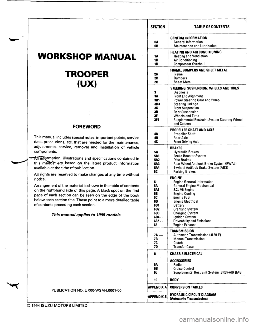
SECTION TABLE OF CONTENTS
. GENERAL INFORMATION OA General Information OB Maintenance and Lubrication
WORKSHOP MANUAL
HEATING AND AIR CONDITIONING 1A Heating and Ventilation
1B Air Conditioning 1D Compressor Overhaul
TROOPER
FRAME, BUMPERS AND SHEET METAL
2A Frame 2B Bumpers
(UX) 2C Sheet Metal
STEERING, SUSPENSION, WHEELS AND TIRES
3 Diagnosis 3A Front End Alignment 3B1 Power Steering Gear and Pump 3B3 Steering Linkage 3C Front Suspension 3D Rear Suspension 3E Wheels and Tires 3F4 Supplemental Restraint System Steering Wheel
FOREWORD and Column
PROPELLER SHAFT AND AXLE 4A Propeller Shaft This manual includes special notes, important points, service 4B Rear Axle
data, precautions, etc. that are needed for the maintenance, 4C Front Driving Axle
adjustments, service, removal and installation of vehicle BRAKES components. 5A Hydraulic Brakes
·~ m rmation, illustrations and specifications contained in 5A1 Brake Booster System
.. _,. 5A2 Disc Brakes ~ this ma. ~-based D.fl the latest product information 5A3 Rear Wheei_Antilock Brake System (RWAL)
available at the tirrHHrl·publication. 5A4 4-wheel Antilock Brake System (ABS)
5C Parking Brakes All rights are reserved to make changes at any time without ENGINE notice. 6· Engine General Information Arrangement of the material is shown in the table of contents &A General Engine Mechanical
on the right-hand side of this page. A black spot on the first 6A1 3.2L VB Engine
page of each section can be seen on the edge of the book &B Engine Cooling
6C Engine Fuel below each section title. These point to a more detailed table &D Engine Electrical of contents preceding each section. 6D1 Battery 6D2 Cranking System
This manual applies to 1995 models. 6D3 Charging System 6D4-Ignition System 6E2. Driveability and Emissions 6F Engine Exhaust
TRANSMISSION 7A-Automatic Transmission (4L30·E) 7B Manual Transmission 7C Clutch 7D Transfer Case
8 CHASSIS ELECTRICAL
ACCESSORIES 9A Radio 9B Cruise Control 9J Supplemental Restraint System (SRS)-AIR BAG
10 BODY
APPENDIX A CONVERSION TABLES PUBLICATION NO. UXOO-WSM-L0001-00
APPENDIXB HYDRAULIC CIRCUIT DIAGRAM (Automatic Transmission)
© 1994 ISUZU MOTORS LIMITED
Page 4 of 1928
.· .· .· .·
q
. . .
.
Page 5 of 1928
GENERAL INFORMATION OA-1
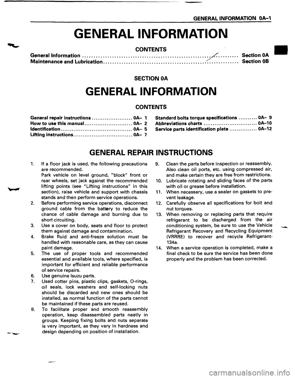
GENERAL INFORMATION
CONTENTS
General Information ........................................................ /.. . . . . . . . . Section OA / Maintenance and Lubrication ............................................. ~·. . . . . . . . . . . . . Section 08
SECTION OA
GENERAL INFORMATION
CONTENTS
General repair instructions ...................... OA-1 Standard bolts torque
specifications .......... OA-9
How to use this manual. ......................... OA-2 Abbreviations
charts ............................. OA-10
Identification
....................................... OA-5 Service
parts identification plate ............... OA-12
Lifting instructions ................................ OA-7
GENERAL REPAIR INSTRUCTIONS
1. If a floor jack is used, the following precautions
are recommended.
Park
vehicle on level ground, "block" front or
rear wheels, set jack against the recommended
lifting points (see "Lifting instructions" in this
section), raise
vehicle and support with chassis
stands and then perform service operations.
2. Before performing service operations, disconnect
ground
cable from the battery to reduce the
chance
of cable damage and burning due to
short circuiting.
3. Use a cover on body, seats and floor to protect
them against damage and contamination.
4. Brake fluid and anti-freeze solution must be
handled with reasonable care, as they can cause
paint damage.
5. The use of proper tools and recommended
essential and available tools, where specified, is
important for efficient and reliable performance
of service repairs.
6. Use genuine lsuzu parts.
7. Used cotter pins, plastic clips, gaskets, 0-rings,
oil seals, lock washers and self-locking nuts
should be discarded and new ones should be
installed, as normal function of the parts cannot
be maintained
if these parts are reused.
8. To facilitate proper and smooth reassembly
operation, keep disassembled parts neatly in
groups. Keeping fixing
bolts and nuts separate
is
very important, as they vary in hardness and
design depending on position
of installation.
9. Clean the parts before inspection or reassembly.
Also clean oil
ports, etc. using compressed air,
and make certain
they are free from restrictions.
10. Lubricate rotating and sliding faces of the parts
with oil or grease before installation.
11. When necessary, use a sealer on gaskets to pre
vent leakage.
12. Carefully observe all specifications for bolt and
nut torques.
13. When removing or replacing parts that require
refrigerant
to be discharged from the air
conditioning system, be sure
to use the Vehicle
Refrigerant Recovery and Recycling Equipment
(VRRRE) to recover and recycle Refrigerant-
134a.
14. When a service operation is completed, make a
final check to be sure the service has been done
properly and the problem has been corrected.
Page 6 of 1928
OA-2 GENERAL INFORMATION
1.
2.
3.
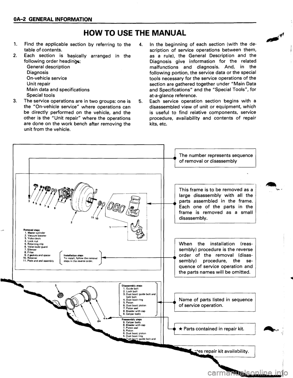
HOW TO USE THE MANUAL
Find the applicable section by referring to the
table
of contents.
4. In the beginning of each section (with the de
scription
of service operations between them,
as a rule), the General Description and the
Diagnosis give
information for the related
malfunctions and diagnosis. And, in the
following portion, the service data or the special
tools necessary
for the service operations of the
section are gathered together under
"Main Data
and
Specifications" and the "Special Tools", for
at-a-glance reference.
Each
section is basically arranged in the
following order headin~:
General description
Diagnosis
On-vehicle service
Unit repair
Main data and specifications
Special tools
The service operations are in
two groups: one is
the
"On-vehicle service" where operations can
be directly performed on the vehicle, and the
other is
the "Unit repair" where the operations
are done on the
work bench after removing the
unit
from the vehicle.
5. Each service operation section begins with a
disassembled
view of unit or equipment, which
is useful
to find relative components, service
procedure, availability and contents
of repair
kits, etc.
,..---------------------------+--e The number represents sequence of removal or disassembly
Removal steps 1. Master cylinder 2. Vacuum booster 3. Yoke clevis 4. Lock nut 5. Retaining clip 6. Valve body guard 7. Silencer 8. Filter 9. 2 gaskets and spacer 10. Retainer 11. Plate and seal assembly (
Installation steps To install, follow the remo ... al steps in the reverse order.
Disassembly steps 1. Guide bolt 2. Lock bolt 3. Dust boot; guide bolt and lock bolt 4. Dust boot ring
5. Piston 6. Dust boot; piston
7. Piston seal B. Bleeder with cap 9. Caliper body
Reassembly steps 9. Caliper body 8. Bleeder with cap 7. Piston seal 5. Piston 6. Dust boot; piston 4. Dust boot ring nust •"·•t; guide bolt and
This frame is to be removed as a
large disassembly
with all the
parts assembled in the frame.
Each one
of the parts in the
frame is removed as a small
disassembly.
When the installation (reas
sembly) procedure is the reverse
order of the removal (disas
sembly) procedure, the se
quence
of service operation and
the parts names
will be omitted.
Name
of parts listed in sequence
of service operation.
* Parts contained in repair kit.
•
-
.,... .
Page 7 of 1928
6.
.. .......,
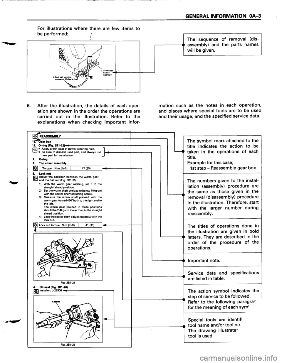
For illustrations where there are few items to
be performed: (
2. :~~~f.' .. ':.. ._----4-----l IINmbly
After the illustration, the details of each oper
ation are
shown in the order the operations are
carried
out in the illustration. Refer to the
explanations
when checking important infor-
r box
GENERAL INFORMATION OA-3
The sequence of removal (dis
assembly) and the parts names
will be given.
mation such as the notes in each operation,
and places
where special tools are to be used
and
their usage, and the specified service data.
12. o-rtng (Fig. 381-22:}-ooolt----------------1---------. hi • Apply a thin coat of power steering fluid. ~ • Be sure to discard used part, and always use
The symbol mark attached to the
title indicates the action
to be
taken in the operations
of each
title. new part for installation. 7. 0-rlng 8. Top cover assembly
~ Torque N·m Ub·ftl I 47 (351
5. Lock nut Eel Adjust the backlash between the worm gear 11:1 and the ball nut (Fig. 381-251. 11 With the worm gear rotating, set it to the
straight ahead position.
21 Setthe worm shaft preload to below 10kg-cm with the sector shaft adjusting screw. 31 Measure the worm shaft preload with the
worm gear turned 450' both to the right and to
the left. The worm gear preload in these positions should be 2-4kg-cm lower than in the straight
ahead position.
41 lock the sector shaft adjusting screw with the lock nut.
lock nut torque N·m Ub·ftl
Fig. 381-25 4. Ollae•l (Fig. 381-281
41 (301
~Installer: J-26508 -'------------,
Example for this case;
1st
step-Reassemble gear box
The numbers given to the instal
lation (assembly) procedure are
the same
as those given in the
removal (disassembly) procedure
in the illustration. Therefore, start
with the larger number during
reassembly.
The titles
of operations done in
the
illustration are given in bold
letters. They are described in the
order
of the procedure of the
operations.
Important note.
Service data and specifications
are listed in table.
The action symbol indicates the
step
of service to be followed.
Refer
to the following paragrar·
for the meaning of each sym'
Special tools are identifi
tool name and/or tool nu
The
drawing illustrate'
tool is used.
Page 8 of 1928
OA-4 GENERAL INFORMATION
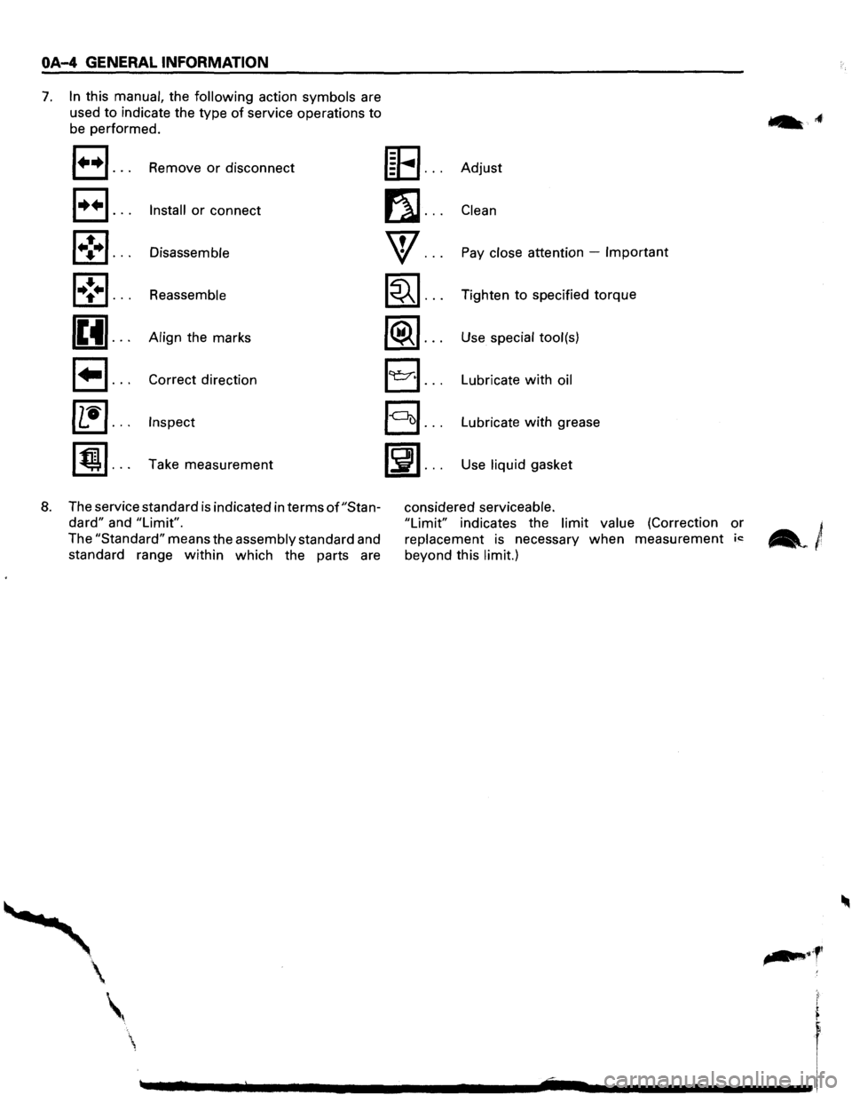
7. In this manual, the following action symbols are
used
to indicate the type of service operations to
be performed.
a ... Remove or disconnect
E) ... Install or connect
1•!•1 ... Disassemble
l•!•l ... Reassemble
(Et ... Align the marks
~ ... Correct direction
~ ... Inspect
[j) ... Take measurement
8. The service standard is indicated in terms of"Stan
dard" and "Limit".
The "Standard" means the assembly standard and
standard range
within which the parts are
[E ... Adjust
fll ... Clean
w ... Pay close attention -Important
~ ... Tighten to specified torque
~ ... Use special tool(s)
E) ... Lubricate with oil
§] ... Lubricate with grease
~ ... Use liquid gasket
considered serviceable.
"Limit" indicates the limit value (Correction or
replacement is necessary when measurement ic:
beyond this limit.)
.. ,f•
Page 9 of 1928
IDENTIFICATION
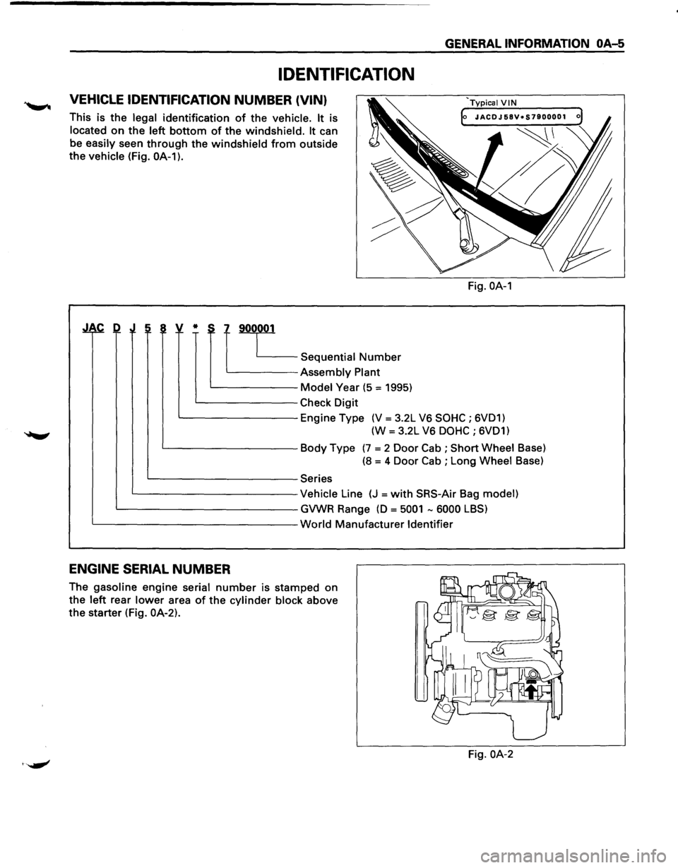
VEHICLE IDENTIFICATION NUMBER (VIN)
This is the legal identification of the vehicle. It is
located
on the left bottom of the windshield. It can
be easily seen
through the windshield from outside
the vehicle (Fig.
OA-1).
~ !~ :i ~ v * ~7L_
~Sequential Number
Assembly Plant
Model Year (5 = 1995)
Check Digit
GENERAL INFORMATION OA-5
Fig. OA-1
Engine Type (V = 3.2L V6 SOHC ; 6VD1)
(W = 3.2L V6
DOHC ; 6VD1)
Body Type
(7 = 2 Door Cab ; Short Wheel Base)
(8 = 4 Door Cab ; Long Wheel Base)
Series
Vehicle Line
(J =with SRS-Air Bag model)
GVWR Range
(0 = 5001 -6000 LBS)
World Manufacturer Identifier
ENGINE SERIAL NUMBER
The gasoline engine serial number is stamped on
the
left rear lower area of the cylinder block above
the starter (Fig. OA-2).
Fig. OA-2
Page 10 of 1928
OA-6 GENERAL INFORMATION
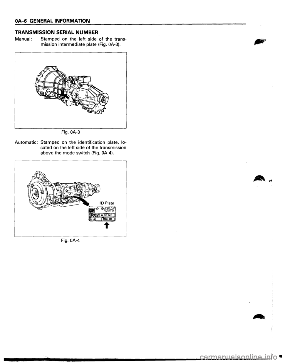
TRANSMISSION SERIAL
NUMBER
Manual: Stamped on the left side of the trans
mission intermediate
plate (Fig. OA-3).
Fig. OA-3
Automatic: Stamped on the identification plate, lo
cated on the left side of the transmission
above the mode switch (Fig.
OA-4).
Fig. OA-4
ID Plate
96017587 0000 000
•