air conditioning ISUZU TROOPER 1998 Service Repair Manual
[x] Cancel search | Manufacturer: ISUZU, Model Year: 1998, Model line: TROOPER, Model: ISUZU TROOPER 1998Pages: 3573, PDF Size: 60.36 MB
Page 3064 of 3573
WIRING SYSTEM 8D – 471
Heater and Air Conditioning
General Description
The circuit consists of pressure switch, A/C switch,
electronic thermostat, blower motor, fan switch,
magnetic clutch of A/C compressor, blower resistor
and relay.
The operation of A/C system is controlled by turning
A/C switch on and off. Electronic thermostat and PCM
can stop operation of A/C temporarily by disconnect-
ing magnetic clutch under the predetermined condi-
tions to adjust room temperature, preventing abnor-
mal rise of engine coolant and reduce engine load
while A/C is in operation.
Refer to Heating, Ventilation and Air Conditioning in
HVAC section.
Page 3248 of 3573
8F±53 BODY STRUCTURE
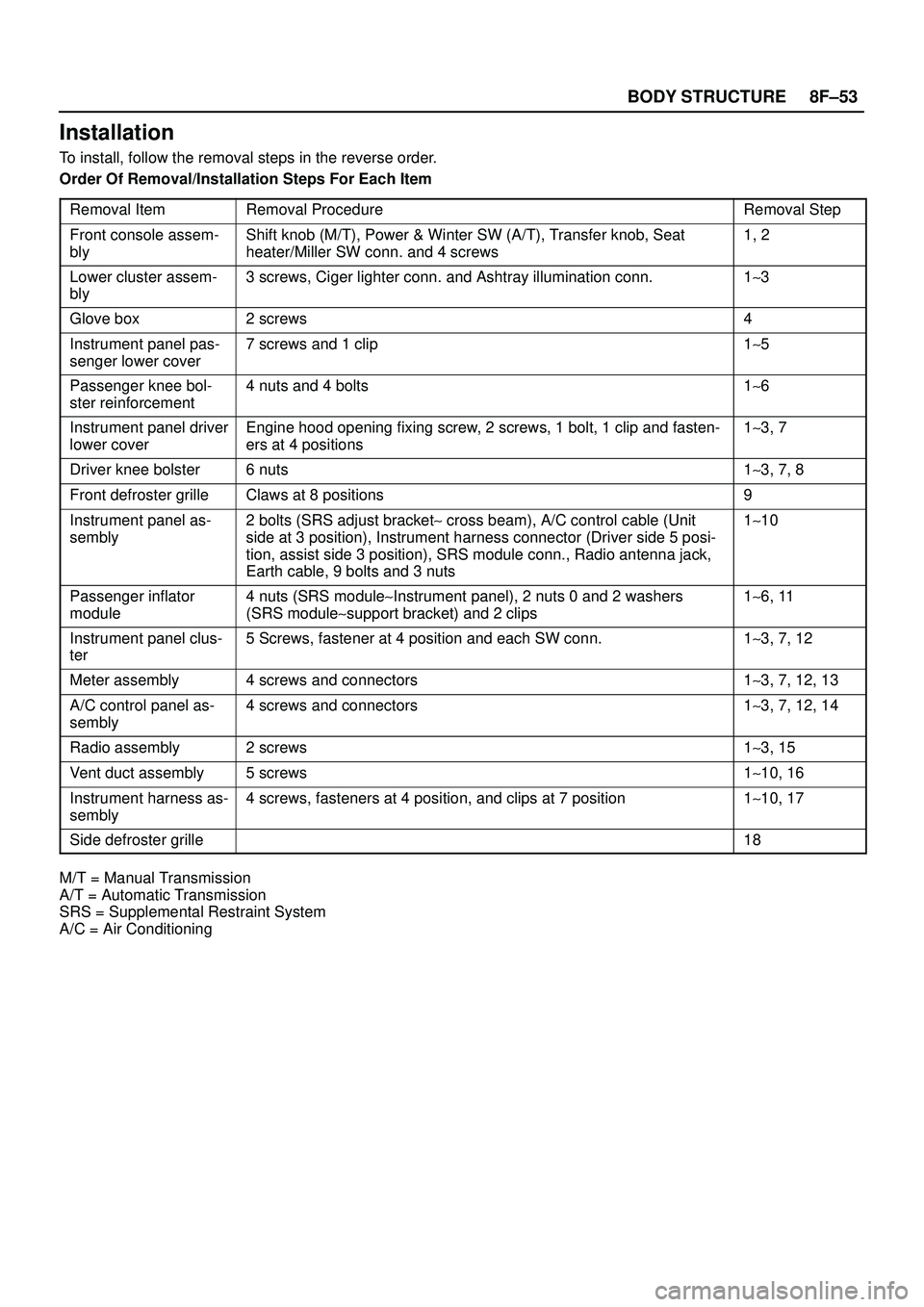
Installation
To install, follow the removal steps in the reverse order.
Order Of Removal/Installation Steps For Each Item
Removal Item
Removal ProcedureRemoval Step
Front console assem-
blyShift knob (M/T), Power & Winter SW (A/T), Transfer knob, Seat
heater/Miller SW conn. and 4 screws1, 2
Lower cluster assem-
bly3 screws, Ciger lighter conn. and Ashtray illumination conn.1~3
Glove box2 screws4
Instrument panel pas-
senger lower cover7 screws and 1 clip1~5
Passenger knee bol-
ster reinforcement4 nuts and 4 bolts1~6
Instrument panel driver
lower coverEngine hood opening fixing screw, 2 screws, 1 bolt, 1 clip and fasten-
ers at 4 positions1~3, 7
Driver knee bolster6 nuts1~3, 7, 8
Front defroster grilleClaws at 8 positions9
Instrument panel as-
sembly2 bolts (SRS adjust bracket~ cross beam), A/C control cable (Unit
side at 3 position), Instrument harness connector (Driver side 5 posi-
tion, assist side 3 position), SRS module conn., Radio antenna jack,
Earth cable, 9 bolts and 3 nuts1~10
Passenger inflator
module4 nuts (SRS module~Instrument panel), 2 nuts 0 and 2 washers
(SRS module~support bracket) and 2 clips1~6, 11
Instrument panel clus-
ter5 Screws, fastener at 4 position and each SW conn.1~3, 7, 12
Meter assembly4 screws and connectors1~3, 7, 12, 13
A/C control panel as-
sembly4 screws and connectors1~3, 7, 12, 14
Radio assembly2 screws1~3, 15
Vent duct assembly5 screws1~10, 16
Instrument harness as-
sembly4 screws, fasteners at 4 position, and clips at 7 position1~10, 17
Side defroster grille18
M/T = Manual Transmission
A/T = Automatic Transmission
SRS = Supplemental Restraint System
A/C = Air Conditioning
Page 3477 of 3573
SUPPLEMENTAL RESTRAINT SYSTEM 9J±40
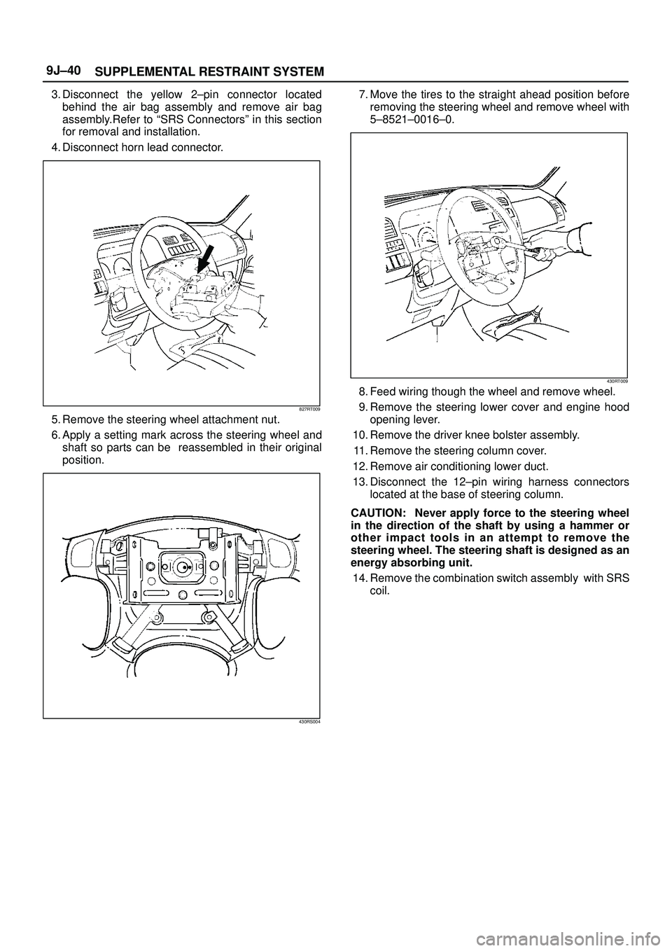
3. Disconnect the yellow 2±pin connector located
behind the air bag assembly and remove air bag
assembly.Refer to ªSRS Connectorsº in this section
for removal and installation.
4. Disconnect horn lead connector.
827RT009
5. Remove the steering wheel attachment nut.
6. Apply a setting mark across the steering wheel and
shaft so parts can be reassembled in their original
position.
430RS004
7. Move the tires to the straight ahead position before
removing the steering wheel and remove wheel with
5±8521±0016±0.
430RT009
8. Feed wiring though the wheel and remove wheel.
9. Remove the steering lower cover and engine hood
opening lever.
10. Remove the driver knee bolster assembly.
11. Remove the steering column cover.
12. Remove air conditioning lower duct.
13. Disconnect the 12±pin wiring harness connectors
located at the base of steering column.
CAUTION: Never apply force to the steering wheel
in the direction of the shaft by using a hammer or
other impact tools in an attempt to remove the
steering wheel. The steering shaft is designed as an
energy absorbing unit.
14. Remove the combination switch assembly with SRS
coil.
Page 3478 of 3573
SUPPLEMENTAL RESTRAINT SYSTEM9J±41
Installation
1. Install the combination switch assembly with SRS
coil.
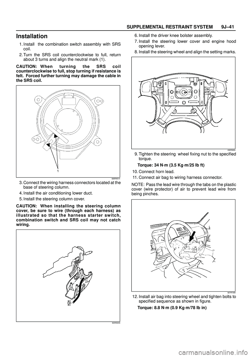
2. Turn the SRS coil counterclockwise to full, return
about 3 turns and align the neutral mark (1).
CAUTION: W h e n t u r n i n g t h e S R S c o i l
counterclockwise to full, stop turning if resistance is
felt. Forced further turning may damage the cable in
the SRS coil.
826RW014
3. Connect the wiring harness connectors located at the
base of steering column.
4. Install the air conditioning lower duct.
5. Install the steering column cover.
CAUTION: When installing the steering column
cover, be sure to wire (through each harness) as
illustrated so that the harness starter switch,
combination switch and SRS coil may not catch
wiring.
825RS048
6. Install the driver knee bolster assembly.
7. Install the steering lower cover and engine hood
opening lever.
8. Install the steering wheel and align the setting marks.
430RS004
9. Tighten the steering wheel fixing nut to the specified
torque.
Torque: 34 N´m (3.5 Kg´m/25 Ib ft)
10. Connect horn lead.
11. Connect air bag to wiring harness connector.
NOTE: Pass the lead wire through the tabs on the plastic
cover (wire protector) of air to prevent lead wire from
being pinches.
827RT009
12. Install air bag into steering wheel and tighten bolts to
specified sequence as shown in figure.
Torque: 8.8 N´m (0.9 Kg´m/78 Ib in)
Page 3482 of 3573
SUPPLEMENTAL RESTRAINT SYSTEM9J±45
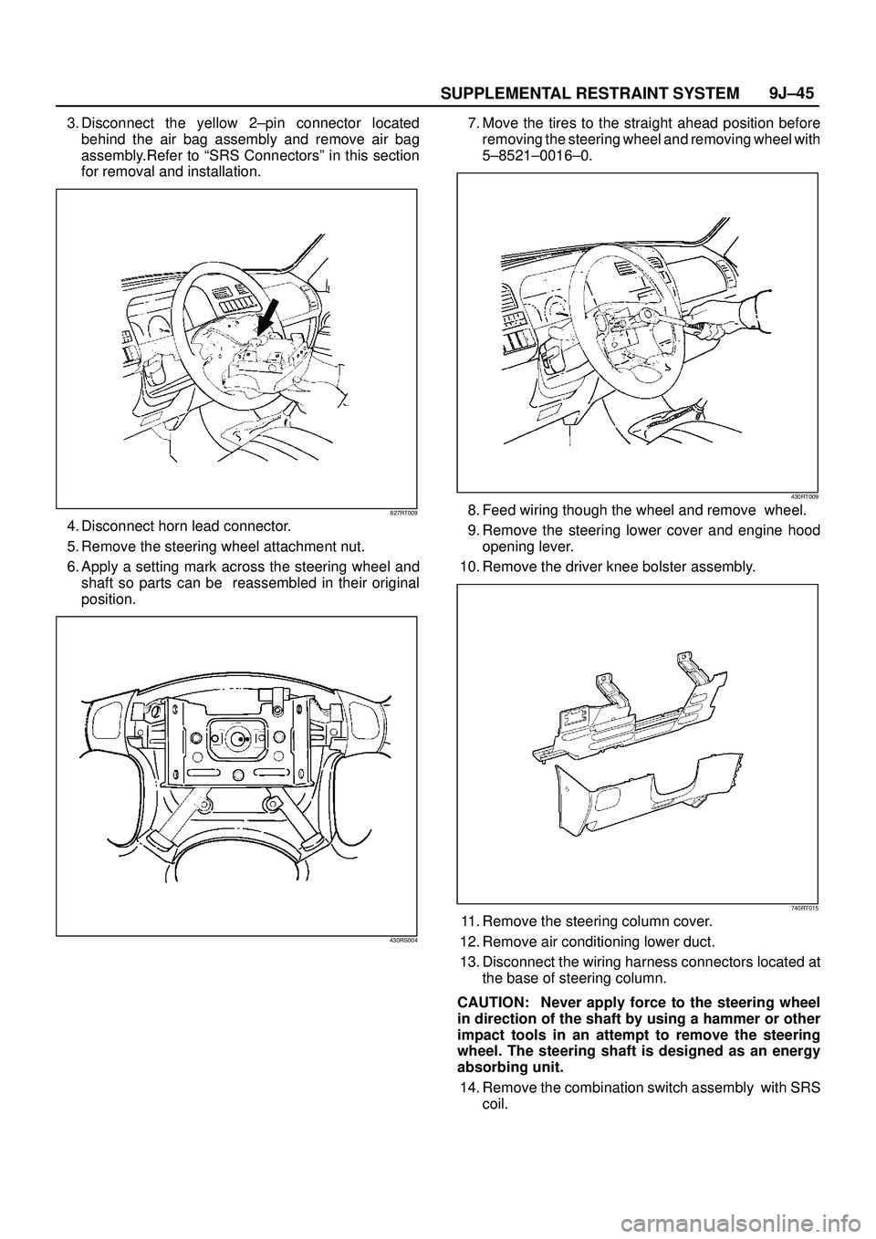
3. Disconnect the yellow 2±pin connector located
behind the air bag assembly and remove air bag
assembly.Refer to ªSRS Connectorsº in this section
for removal and installation.
827RT009
4. Disconnect horn lead connector.
5. Remove the steering wheel attachment nut.
6. Apply a setting mark across the steering wheel and
shaft so parts can be reassembled in their original
position.
430RS004
7. Move the tires to the straight ahead position before
removing the steering wheel and removing wheel with
5±8521±0016±0.
430RT009
8. Feed wiring though the wheel and remove wheel.
9. Remove the steering lower cover and engine hood
opening lever.
10. Remove the driver knee bolster assembly.
740RT015
11. Remove the steering column cover.
12. Remove air conditioning lower duct.
13. Disconnect the wiring harness connectors located at
the base of steering column.
CAUTION: Never apply force to the steering wheel
in direction of the shaft by using a hammer or other
impact tools in an attempt to remove the steering
wheel. The steering shaft is designed as an energy
absorbing unit.
14. Remove the combination switch assembly with SRS
coil.
Page 3561 of 3573
PAGE BACK PAGE NEXT
THIS MALUAL INCLUDES THE FOLLOWING SECTIONS:
SECTION No. CONTRNTS
1A HEATING AND VENTILATION
1B AIR CONDITIONING
1D COMPRESSOR OVERHAUL